Table of Contents
Advertisement
Advertisement
Table of Contents

Related Manuals for IDTECK iTDC EIO8


Summary of Contents for IDTECK iTDC EIO8
- Page 1 Quick Installation Guide iTDC / iTDC-SR EIO88 MULTI DOORS ACCESS CONTROL SYSTEM...
- Page 2 ※ iTDC Quick Installation Guide 1. iTDC/iTDC-SR INSTALLATION LAYOUT 1.1 LAYOUT TO CONTROL 2 DOORS The figure below is iTDC/iTDC-SR installation layout to control 2doors. You can install readers instead of No.8, Exit Buttons. In this case, connect each reader to reader port No.2 of iTDC/iTDC-SR, reader port No.4 of iTDC/iTDC-SR.
- Page 3 ※ iTDC Quick Installation Guide 1.2 LAYOUT TO CONTROL 3 DOORS You have to attach EIO88 to control more than2 doors. The figure below is iTDC/iTDC-SR installation layout to control 3 doors. (Figure: iTDC/iTDC-SR Installation Layout to Control 3 Doors) Code PC for installing application software, STARWATCH ①...
- Page 4 ※ iTDC Quick Installation Guide 1.3 LAYOUT TO CONTROL 4 DOORS The figure below is iTDC/iTDC-SR installation layout to control 4 doors. (Attach EIO88) (Figure: iTDC/iTDC-SR Installation Layout to Control 4 Doors) Code PC for installing application software, STARWATCH ① iTDC PRO I, II, STARWATCH STANDARD iTDC or iTDC-SR ②...
- Page 5 ※ iTDC Quick Installation Guide 1.4 WIRING PARTS CODE 1.2.1 iTDC/iTDC-SR Code ① Power Port Terminal Block RS422 Communication Port Terminal Block ② RS232 Communication Port Terminal Block ③ ④ TTL Output Port Terminal Block ⑤ Relay Output Port Terminal Block Board ID Setting Switch ⑥...
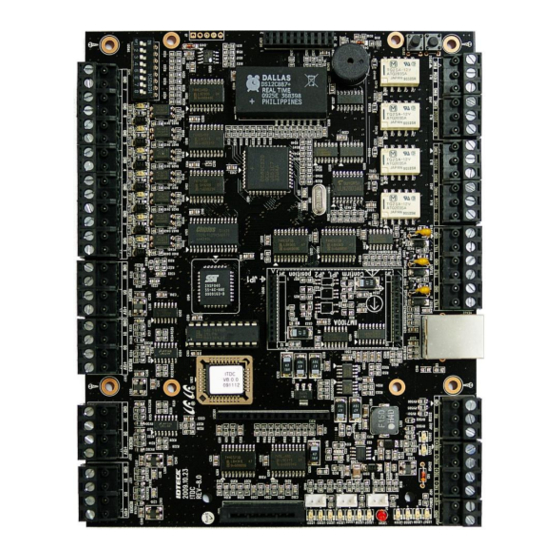
- Page 6 ※ iTDC Quick Installation Guide 1.2.1 EIO88 Code ① Input Port Terminal Block (#1 ~ #4) ② Output Port Terminal Block (#5 ~ #8) ③ Input Port Terminal Block (#1 ~ #4) ④ Output Port Terminal Block (#5 ~ #8) Mar.11.2010...
- Page 7 ※ iTDC Quick Installation Guide 2. BOARD ID SETTING Board ID is unique address used for Serial Communication. If more than one iTDC/iTDC-SR board is used, Board IDs must be different from each others. There is an 8 channel DIP switch on the upper left side of the iTDC/iTDC-SR board for Board ID setting. Each channel of DIP switch has assigned address value and the Board ID is the sum value of each switch set to “ON”...
- Page 8 ※ iTDC Quick Installation Guide 3. WIRING Caution Wiring must be done before main power switched on to the iTDC/iTDC-SR. Wiring after main power switched on may cause electrical shock. 3.1 EARTH GROUND WIRING [IMPORTANT] When installing iTDC/iTDC-SR, you must connect GND wire of Power terminal block to 1 class EARTH GROUND.
- Page 9 ※ iTDC Quick Installation Guide 3.3 COMMUNICATION CABLE CONNECTION 3.3.1 MULTIPLE CONNECTION THROUGH RS422 COMMUNICATION RS422/RS232 converter is required for RS422 communication. When connecting multiple devices, you can connect up to 32 devices for 1 loop. 1) Connection between Host PC and RS422/RS232 Converter Connect the Host PC and the RS232/RS422 Converter using Cable If the Host PC has Serial Port, connect RS422/RS232 Converter to the Serial Port using 9 pin Serial Cable.
- Page 10 ※ iTDC Quick Installation Guide Figure: RS422 Multiple Connection Caution ○ Recommended Communication Cable It is recommended to use STC(Shielded Twisted Pair) cable for RS422 communication. ○ GND Connection As the figure above, connect an end of Shield wire to the Power terminal block(GND) of iTDC/iTDC-SR. If you connect both ends of Shield wire to the Power terminal block(GND) of iTDC/iTDC-SR, currents may flow because voltage levels of both sides are different then it causes communication error.
- Page 11 ※ iTDC Quick Installation Guide 3.3.2 RS422 COMMUNICATION CONNECTION USING TCP/IP MODULE (IIM7100A) Using an IP (TCP/IP module), multiple iTDCs can communicate with the Host PC. When connecting multiple devices, you can connect up to 32 devices for 1 loop 1) Connection between Host PC and the First iTDC/iTDC-SR Attach TCP/IP module on the fist iTDC/iTDC-SR and then connect it with the host computer by LAN cable.
- Page 12 ※ iTDC Quick Installation Guide (Figure: RS422 Multiple Connection Using TCP/IP Module) Caution ○ Recommended Communication Cable It is recommended to use STC(Shielded Twisted Pair) cable for RS422 communication. ○ GND Connection As the figure above, connect an end of Shield wire to the Power terminal block(GND) of iTDC/iTDC-SR. If you connect both ends of Shield wire to the Power terminal block(GND) of iTDC/iTDC-SR, currents may flow because voltage levels of both sides are different then it causes communication error.
- Page 13 ※ iTDC Quick Installation Guide 3.3.3 TCP/IP Module (IIM7100A) Setting To do TCP/IP communication through TCP/IP Module(IIM7100) on the iTDC/iTDC-SR board, use TCP/IP Module(IIM7100) setting program(IIM100A Configuration Tool) to set information for Network and Serial communication. 1. Install TCP/IP Module(IIM7100) setting program,IIM100A Configuration Tool. The Program to set network and check operation status is contained in Application software (iTDC PRO I, II, STARWATCH STANDARD) CD.
- Page 14 ※ iTDC Quick Installation Guide In the ‘Board List’, MAC address of TCP /IP Module is displayed. 4) Check MAC address of TCP/IP Module (described on TCP/IP module) and then select it. Setting information is displayed as below. 5) Select ‘Network’ tab. Input network information of selected TCP/IP module to ‘Local IP’, ‘Subnet’, and ‘Gateway’.
- Page 15 ※ iTDC Quick Installation Guide Column Name Setting Value Speed 9600 DataBit Parity None Stop Bit Flow CTS/RTS 7) Select ‘Option’ tab. Select option values (‘Inactivity Time’, ‘Time’, ‘Size’ and ‘Char’ ) of selected TCP/IP module. Select ‘30000’ for ‘Inactivity Time’, ‘0’ for ‘Time’, ‘0’ for ‘Size’, ‘00’ for ‘Char’. Refer to table below. Column Name Setting Value Inactivity Time...
- Page 16 ※ iTDC Quick Installation Guide 3.4 READER WIRING Connect RF reader to Reader Port of iTDC/iTDC-SR as follows. Wiring below is an example of Reader Port #1(EX_RD1) connection. Wiring for reader Port #2(EX_RD2), #3(EX_RD3), #4(EX_RD4) is also the same as description below. - Connect +12V (red) wire of RF reader to Reader Port terminal block (+12V) of iTDC/iTDC-SR.
- Page 17 ※ iTDC Quick Installation Guide 3.5 INPUT WIRING Connect Door contact and exit button to Input Port terminal block (INPUT_1 ~ INTPUT_7) of iTDC/iTDC-SR as follow. - Door 1: Connect Exit Button to Input Port terminal block (INPUT_1) of iTDC/iTDC-SR. - Door 1: Connect Door Contact to Input Port terminal block (INPUT_2) of iTDC/iTDC-SR.
- Page 18 ※ iTDC Quick Installation Guide 3.6 EARTH GROUND CONNECTION WHEN INSTALLING THE READER ON METAL FRAME If you install input devices such as a reader and an exit button on the metal flame, Earth GND should be connected to the metal frame. Caution If you don’t connect Earth GND to metal frame, static electricity from the metal frame flows in the device then it becomes the reason of malfunctions and shortens device’s lives.
- Page 19 ※ iTDC Quick Installation Guide 3.7 OUTPUT WIRING Door Lock or Alarm Device can be connected to Output Port terminal block (Relay outputs) of iTDC/iTDC-SR. Connect input devices as follows. DOOR LOCK WIRING 3.7.1 POWER FAIL SAFE DOOR LOCK WIRING; ...
- Page 20 ※ iTDC Quick Installation Guide POWER FAIL SECURE DOOR LOCK WIRING; - Connect +12V wire of DC12V power supply to Output Port terminal block (RCOM1) of iTDC/iTDC-SR. - Connect (+) wire of Door Lock to Output Port terminal block (RNO1) of iTDC/iTDC-SR. - Connect (-) wire of Door Lock to GND(-) wire of DC12V power supply.
- Page 21 ※ iTDC Quick Installation Guide 24V DOOR LOCK AND AUTOMATIC DOOR WIRING When you control 24V door lock or automatic door, wire the door lock depending on Power Fail Safe or Power Fail Secure. But separate power source must be applied and use external Relay in both Power Fail Secure and Power Fail Safe door lock.
- Page 22 ※ iTDC Quick Installation Guide ALARM DEVICE WIRING 3.6.2 - Connect +12V wire of DC12V power supply to Output Port terminal block (RCOM2) of iTDC/iTDC-SR. - Connect (+) wire of Alarm Device to Output Port terminal block (RNO2) of iTDC/iTDC-SR. - Connect (-) wire of Alarm Device to GND(-) wire of the DC12V power supply.
- Page 23 ※ iTDC Quick Installation Guide 3.6.3 INPUT/ OUTPUT PORT SETTING FOR 2DOOR / 3DOOR / 4DOOR Above wiring description is applied when 2 doors are controlled. If you want to control 3 doors or 4doors, attach EIO88 and then change door setting as the table below. You can set the number of doors in ‘CONTROLLER DEFINITION’...
- Page 24 ※ iTDC Quick Installation Guide 4. SYSTEM INITIALIZATION After all wiring process is done, you must initialize the iTDC/iTDC-SR. Initialization is used to clear all data stored in the controller and reload default setting values (factory setting values). During production and test process of the device, arbitrary setting values may be saved. Thus, restore it to default values by Initialization.