Table of Contents
Advertisement
Quick Links
Advertisement
Table of Contents

Related Manuals for IDTECK 505R Series


Summary of Contents for IDTECK 505R Series
-
Page 3: Table Of Contents
차례 ..............차례 ..........1 Safety Information ........1 IMPORTANT SAFETY INSTRUCTIONS ............2 GENERAL ............3 FEATURES ............4 Specification ........5 IDENTIFYING SUPPLIED PARTS ........... 6 Product overview ............1 FUNCTIONS ..........2 PRODUCT EXPANATION ............2.1 Front View ............ -
Page 4: 차례
..........2.4 Reverse Diode Connection ........... . . 8 INSTALLATION ..........1 WALL MOUNT INSTALLATION ..........2 SYSTEM INITIALIZATION ............. . 3 WIRING ............. . 3.1 Power ........... . . 3.2 Input Connection ..........Exit Button Connection ......... . Door Contact Sensor Connection ....Auxiliary Input Connection (Applied to Aux Input IN1, Aux Input IN2) ....... . - Page 5 ......4 SETTING MAXIMUM NUMBER OF CARDHOLDER IDS ......... . . 5 REGISTERING CARDHOLDER IDS ............11 OPERATION ........... 1 NORMAL OPERATION ............2 DEFAULT SETTING ..........12 SETTING CHANGES ............1 Setup Menu F1 ............1.1 Time Setting ..........1.2 Communication Address ............
- Page 6 ........... . Description of Fields ............3.2 ID Deletion ............. . 3.3 ID List ........... 3.4 Registered ID Count ............3.5 ID Memory ............3.6 Event List ............3.7 Event Count ............4 Setup Menu F4 ........... . . 4.1 Firmware Version ............4.2 Memory Test ............
- Page 7 ........4.1 A MASTER ID may have changed. . . 5 The device work well with RF Card, but does not work when inputting card number........5.1 Please check if Keypad is set to "USE"......6 A buzzer keeps making sounds. "Bee~ Bee~ Bee~" ........
-
Page 9: Safety Information
Safety Information CAUTION: TO REDUCE THE RISK OF ELECTRIC SHOCK, DO NOT REMOVE COVER (OR BACK) NO USER SERVICEABLE PARTS INSIDE. REFER SERVICING TO QUALIFIE D SERVICE PERSONNEL. This symbol indicates that dangerous voltage consisting a risk of electric shock is pres ent within this unit. - Page 10 3. Do not connect multiple controllers to a single adapter. Exceeding the capacity may cau se abnormal heat generation or fire. 4. Securely plug the power cord into the power receptacle. Insecure connection may caus e fire. 5. When installing the controller, fasten it securely and firmly. The fall of controller may ca use personal injury.
-
Page 11: Important Safety Instructions
IMPORTANT SAFETY INSTRUCTIONS 1. Read these instructions. 2. Keep these instructions. 3. Heed all warnings. 4. Follow all instructions. 5. Do not use this apparatus near water. 6. Clean only with dry cloth. 7. Do not block any ventilation openings. Install in accordance with the manufacturer’s ins tructions. -
Page 13: General
4” inch RF reader and keypad for Personal Identification Numbers (PIN), the Star 505 R (iPASS IP505R, IDTECK SR505) offers up to two levels of ID verification. You can verify by Proximity Card, PIN or both and multiple verification levels can be custom programmed for e ach user or user group. -
Page 15: Features
FEATURES 125 KHz Standalone Proximity Controller (Optional 13.56MHz Smart Card) ● Dual Function for Access Control and Time & Attendance ● Dynamic Control of Memory up to 10,000 Users / 50,000 Event Buffers (Selectable) ● Standalone / Network Communication via RS232, RS422 and TCP/IP (External LAN Conv ●... -
Page 17: Specification
Specification Star 505R Model Dual 8bit Microprocessor 128KByte Flash Memory Memory Program Mem 1MByte Flash Memory Data Memory 10,000 ~ 50,000 Users(Default:10,000) User 10,000 ~ 50,000 Event Buffers(Default:50,000)( The Sum of Users Event Buffer and Events Cannot Exceed 60,000) DC +12V / Max.150mA Power / Current 1ea (26bit Wiegand, 4/8bit Burst for PIN) External Reade... - Page 18 0 to +40C (+32 to +104F) Operating temperature 10% to 90% Relative Humidity Non-Condensing Operating Humidity Dark, Pearl, Gray / Polycarbonate Color / Material 150mm x 120mm x 39.5mm (5.9” x 4.72” x 1.55”) Dimension (W x H x T) 400g Weight FCC, UL, CE, RoHS, KC...
-
Page 19: Identifying Supplied Parts
IDENTIFYING SUPPLIED PARTS Please unpack and check the contents of the box. p.11... -
Page 21: Product Overview
Product overview FUNCTIONS Stand-Alone Operation The Star 505R is capable of having 2 readers (1 Door Control). The unit receives card I D numbers from the proximity readers and determines whether or not to unlock the d oor. When an input signal is entered, for example from a Sensor activated or an Exit b utton pressed, the controller generates and logs an appropriate response by input sig nals. - Page 22 Anti-Pass-Back By using an additional proximity reader, the Anti-Pass-Back mode can be set. The Anti -pass-back mode prevents entry or exit when the registered user did not properly follo wed one entry and one exit by the Anti-pass-back rule. The same user cannot enter t wice with the entry card without properly using the exit before.
-
Page 23: Product Expanation
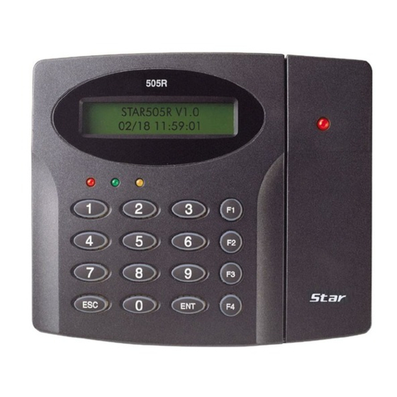
output and an alarm event will be sent to the host PC. PRODUCT EXPANATION Front View LCD Display: LCD displays Star 505R’s status. 3LEDs: When the power is supplied to Star 505R, the red LED is turned on. When the Relay #1 is operated, the green LED is turned on. When the Relay #2 is operated, the yellow LED is turned on. -
Page 24: Rear View
Rear View Initialization Switch This switch is used to initialize Star 505R. For initialization, press down this switch and then keep it more than 2 seconds. Refer to ‘8.2 System Initialization’ for more details. Communication Display LED # 3, 4(yellow, green) LED will twinkle during RS232, RS422 and TCP/IP communicatio If the LAN is connected normally during TCP/IP communication, green LED will turn o n. -
Page 25: Wire Color Table
WIRE COLOR TABLE IO PORT NAME SIGNAL NAME COLOR CODED POWER CON7 DC +12V Main Power(+12V) Black Power Ground OUTPUT CON4 COM(1) Gray with Red Stripe Door Relay(COM) NC(1) Blue with White Stripe Door Relay(NC) NO(1) White with Red Stripe Door Relay(NO) COM(2) White... - Page 26 IO PORT NAME SIGNAL NAME COLOR CODED TTL2/ Weigand D1 Out Brown with White Stripe TTL Output2 Not use Green with Red Stripe OK Signal Out Not use Blue with Red Stripe Error Signal Out Tamper Switch Out Yellow with White Stripe Tamper Switch Out RS232 INTERFACE CON2...
-
Page 27: Installation Checkpoints & Tips
INSTALLATION CHECKPOINTS & TIPS CHECK POINTS BEFORE INSTALLATION Installation Layout p.19... -
Page 28: Recommended Cable Type And Permissible Length Of Cable
Recommended Cable Type and Permissible Length of Cable Reference Description Cable Specification Maximum Distance ① Star 505R Power (DC1 Belden #9409, 18 AW DC Power -> Star 505R 2 conductor, unshielde ②* Reader (Power and Dat Belden #9512, 22 AW 150m Extra Reader ->... -
Page 29: Check Points During Installation
CHECK POINTS DURING INSTALLATION Termination Resistor Termination resistors are used to match impedance of the network to the impedance of the transmission line being used. When impedance is mismatched, the transmitted signal is not completely absorbed by the receiver and a portion of signal is reflected back into the transmi ssion line. -
Page 30: Reverse Diode Connection
There will be three grounding points where you can find during installation; 1. Earth Ground 2. Chassis Ground 3. Power Ground The most important point for grounding system is not to connect both ends of shield wires t o the grounding system; in this case there will be a current flow through the shield wire whe n the voltage level of both ends of shield wire is not equal and this current flow will create n oise and interfere to communications. - Page 31 b this surge voltage. CHECK POINTS DURING INSTALLATION p.23...
-
Page 33: Installation
INSTALLATION WALL MOUNT INSTALLATION Real size template is on 59p in this manual. Tear off the template page and attach it to the wall. And then follow steps below to install the Star 505R. (You can install the Star 505R dir ectly, if the gang box is installed on the wall.) 1. -
Page 34: System Initialization
Before mounting the Star 505R unit to the Wall Mount bracket, operational test of the unit should be completed, as the locking pins will lock the unit to the Wall Mo unt. Removing the unit from the Wall Mount bracket after they have been installe d together may cause damages to the bracket and render its effectiveness. -
Page 35: Wiring
Press the key <1> if you wish to initialize the Star 505R. Initialization is processing Rebooted automatically after Initialization WIRING Power Connect (+) wire of DC +12V power to the DC +12V (Red wire) of Star 505R. Connect GND (-) wire of DC +12V power to the GND (Black wire) of Star 505R. WIRING p.27... -
Page 36: Input Connection
Input Connection Exit Button Connection Connect one wire from an Exit Button to the Orange wire. ● Connect the other wire from the Exit Button to the GND. ● Door Contact Sensor Connection Connect one wire (COM) from a Door Contact Sensor to the Yellow wire with Red strip ●... -
Page 37: Output Connections
P MENU” -> “5. IN/OUT DEFINE”-> 18. CUT OFF ALARM”. Output Connections Door Lock (Power Fail Safe) Connection (Relay 1) Connect COM port of Relay 1(Gray with Red Stripe) to + 12V (Red wire) ● Connect NC port of Relay 1(Blue with White Stripe) to (+) wire of Door Lock Device. ●... -
Page 38: Wiegand Data Connection (Applicable To Reader Mode)
Please add one diode as shown above. A fast recovery diode (Current: Min. 1A), 1 N4001 - 1N4007 or similar, is recommended. Wiegand Data Connection (Applicable to Reader Mode) Connect DATA0 IN wire of controller to TTL1/D0 (TTL Output) wire of 505R (Orange wit ●... -
Page 39: Recommended Readers
Standard 34bitWiegand+8bit Burst Format Proximity and Keypad Readers. ● Recommended Readers: Star 505R/IP505R: RF-TINY, RF10, RF20, RF30, RFK101, FGR006, FGR006EX, iP10, iP20, iP30, iPK101. SR505: SR10, SR20, SR30, SRK101, FGR006SR, FGR006SRB. WIRING p.31... -
Page 41: Communication
COMMUNICATION RS232 COMMUNICATION PORT CONNECTION A 9-PIN connector is required to connect the Star 505R to the PC via RS232 communication. Please follow the instructions below: Connect RS232-TX (Black wire with White stripe) port of Star 505R to the PIN 2 of the 9 ●... -
Page 42: Rs422 Connection (Multiple Connection Of Star 505Rs)
Connect RS422-TX (+) (Gray wire) of Star 505R to RS422-RX (+) port of converter. ● Connect RS422-TX (-) (Yellow wire) of Star 505R to RS422-RX (-) port of converter. ● Connect RS422-RX (+) (Brown wire) of Star 505R to RS422-TX (+) port of converter. ●... -
Page 43: Tcp/Ip Communication Port Connection
V. Plug in the RS232 9PIN connector of the converter to the COM1 or COM2 port of the PC. VI. Install and run Star 505R Application Software TCP/IP COMMUNICATION PORT CONNECTION Optional TCP/IP module is required to use TCP/IP communication between the Star 505R an d the PC. -
Page 44: Tcp/Ip Converter (External Converter)
TCP/IP CONVERTER (EXTERNAL CONVERTER) When you use the TCP/IP converter, choose only one converter between RS232 and RS422. INTERFACE STAR 505R ILAN422 LINE COLOR TX (CON2) RX (RS232 DSUB9) BLACK+WHITE RS232 RX (CON2) TX (RS232 DSUB9) RED + WHITE GND(CON2) BLACK TX+ (CON3) RX+ (RS422 CONNECTOR) -
Page 45: Initial Setup
INITIAL SETUP SYSTEM INITIALIZATION Press and hold the initialization button. Apply DC +12V power to the Star 505R. Release the button when the LCD displays “Initialize OK?” After installation and cable connections are completed, apply power (DC12V) to the Star 50 5R with the initialization button held down. -
Page 46: Time / Date Setting
up menus by pressing the <F1> key for “SETUP MENU F1”, <F2> key for “SETUP MENU F2”, <F3> key for “SETUP MENU F3” and <F4> key for “SETUP MENU F4”. There are setting items i n the main Setup Menu and you can scroll up or down the menu by pressing the <4> or <6> key. -
Page 47: Registering Cardholder Ids
, “30000/30000”, “40000/20000” or “50000/10000” (No. of IDs / No. of events), and then p ress <ENT> again to confirm. Prior to changing the maximum number of cardholders, you must clear the event data from the memory. Because entering the Setup Mode itself generates an event, you must always initialize the event memory prior to changing the maximum ID nu mber setting. -
Page 49: Operation
OPERATION NORMAL OPERATION Power On When the power is applied to Star 505R, the “RED LED” is turned on. Registered Card Reading When a registered card (or PIN) is read, the door (Relay1) will open for 3 seconds wit h the “LED” on. Exit Button To make a request for exiting from inside, an Exit Button (Or External Reader) can be used. -
Page 50: Default Setting
DEFAULT SETTING When you operate the Star 505R first time or you initialize the Star 505R, the controller will set up all values to default settings (Factory Settings). You can change the settings for desire d application. Please refer to the “APPENDIX” section at the back of this manual for the defa ult setting values. -
Page 51: Setting Changes
SETTING CHANGES p.43... - Page 52 To setup or to change the 505R settings, you have to enter the setup mode first. T o do so, enter the Master ID (Default=00000000)* and press the <ENT> key. Ther e are 4 main Setup menus and you automatically get into “SETUP MENU F1” first. Y ou can move to other setup menus by pressing the <F1>...
-
Page 53: Setup Menu F1
Setup Menu F1 Setup Menu F1 p.45... -
Page 54: Time Setting
Time Setting The LCD displays the current time. To change the time, press <ENT>, enter 15 Digits in a “YY YYMMDDhmmssW” format, and then enter <ENT> again to confirm. NOTE: For the days of the week (W), 1 : Sun, 2 : Mon, 3 : Tue, 4 : Wed, 5 : Thu, 6 : Fri, 7 : Sat. e.g. -
Page 55: Reader1 Mode
Baud Rate is the measure of speed in serial communication. As for the communication addr ess, the baud rate you set here should match the value you set on the software. Baud Rates of 4800bps, 9600bps, 19200bps, 38400bps, 57600bps and 115200bps are sup ported, and 9600bps is recommended. -
Page 56: Reader 2 Mode
RF + Password Users can access the door by presenting their card or entering their ID number and th en verifying their identity by a Password. Reader 2 Mode If you have an external reader connected to the 505R (referred to herein as Reader 2), you must adjust this setting according to what access mode is used on Reader 2. -
Page 57: System Initialization
Master ID is the number/card that you use to enter the Setup Mode. For security reasons, it i s advisable that you change the default Master ID immediately and keep the new Master ID / card confidential. Beware that if you forget the Master ID, you cannot access the Setup Mode. To change the Master ID, press <ENT>, and then either enter the desired 8Digit Master ID or present a card to the reader. -
Page 58: Card Id Clear
To initialize the 505R, press <ENT>, and then press <1> to confirm. If you wish to cancel and exit without initialization, press <0> instead. Device address and communication speed is ma intained. Card ID Clear Card ID clear allows you to delete all the card data from the 505R. To clear the card data sto red in the memory, press <ENT>, and then press <1>... -
Page 59: Time Schedule Clear
1.10 Time Schedule Clear T/S Clear allows you to delete all the data related to time scheduling, such as Time Schedule s, Holiday and Reader Time Schedules, Holiday Codes, etc. To clear the time schedule data st ored in the memory, press <ENT>, and then press <1> to confirm. If you wish to cancel and e xit, press <0>... -
Page 60: Setup Menu F2
Setup Menu F2 p.52 SETTING CHANGES... -
Page 61: Time Schedule
Time Schedule Setup Menu F2 p.53... - Page 62 You can define up to 10 time schedule codes. Time schedule code 00 is the default code an d can be used to allow round-the-clock access. You can define time schedule codes 01 to 10. Each time schedule code has 8 programmable days (i.e. Sun, Mon, Tue, Wed, Thu, Fri, Sat a nd holiday) and each day has 5 time intervals.
-
Page 63: Holiday T/S
Holiday T/S You can define up to 10 Holiday T/S codes. Holiday T/S code 00 is the default code without any holidays. (This means that applying Holiday T/S code 00 is the same as applying no holid ays at all.) You can define Holiday T/S codes 01 to 10. Each holiday schedule code can have up to 32 holidays defined. -
Page 64: Holiday Code
You can also define time schedule codes using the Application Software. For more information, please refer to the Software Manual. Holiday Code The Holiday code setting lets you link a holiday schedule to a time schedule. The default holi day schedule code is 00, which means no holidays are applied to the time schedule. Use <4>... -
Page 65: Input / Output Definition
Input / Output Definition In/Output Define allows you to adjust In/Output settings (Output activation time, In/Output Time Schedule, Cut-Off Check, etc.). To change the In/Output Settings, press <ENT> and select an item using <4> or <6> key, and press <ENT> again. After the cursor appears, enter the 10Digit number for the desired settin g. -
Page 66: Output Time Setting
The 14.Duress mode setting allows you to decide the output signal time for when access is granted following a duress event. When a particular event occurs, the 505R will generate an output signal for Relays #1 and #2, TTL #1 and #2, and Buzzer for the length of time defined for each. Output Time Setting Output Time Set allows you to define the unit of time. -
Page 67: Anti-Passback
Anti-Passback The Anti-Pass Back feature is used to prevent an identical user from entering or exiting the d oor more than twice in a row so that employees cannot pass back their cards to their cowor kers. Anti-Pass Back can be applied only when an Exit Reader is installed. “DO NOT” enable it if an “Exit Button”... -
Page 68: Event Alarm
If you choose “Disable”, you cannot gain access via password input when using RF +PW mode. To enable or disable PIN Input, press <ENT> and press <4> or <6> to select “ENABLE” or “DIS ABLE”, and then press <ENT> again to confirm. Event Alarm Event Alarm allows you to decide whether to enable or disable the event memory full alarm. -
Page 69: Door Open Alarm Time
Duress Mode enables a cardholder under duress to activate a silent alarm to notify the securi To enable or disable the Duress Mode and / or set the Duress Password, press <ENT> and pr ess <4> or <6> to select either “DISABLE” or “ENABLE” If you select “ENABLE” the LCD will dis play the current “DURESS PASSWORD”. -
Page 70: Lcd Display
For this application, a Door Contact Sensor must be installed on the door. 2.12 LCD Display LCD DISPLAY allows you to decide whether to display the card number or the status messag e on the LCD when access is granted or denied. To change the setting, press <ENT> and pres s <4>... -
Page 71: Ttl Weigand Output
2.14 TTL WEIGAND Output This function allows whether to use “TTL Output” as “WEIGAND Output” The default value is “NOT USE” You can select setup status by using “<4> or <6>” keys If you press “ENTER” after choosing “TTL WEIGAND” to “USE”, TTL,1,2 setup values would be initialized to “00”. -
Page 72: Setup Menu F3
Setup Menu F3 p.64 SETTING CHANGES... -
Page 73: Id Registration
ID Registration Registration allows you to add new cardholders to the 505R. To add a new cardholder ID, pr ess <ENT>. Either present a card you wish to register to the 505R or enter the card number (ID) via the k eypad and press <ENT>. -
Page 74: Description Of Fields
Description of Fields PW (Password) Enter the 4Digit password. Password verification can be enabled in 11.1.4. Reader1 Mode. This field is compulsory even if you do not use password verification. TS (Time Schedule) If you wish to apply a certain time schedule to the cardholder, enter the T/S code. If y ou wish to allow the cardholder round-the-clock access, enter 0. -
Page 75: Id List
e LCD. If the card you presented or the card number you entered is not found, the “UNREGIS TERED ID” message will be displayed. ID List ID List allows you to search for a certain registered card or view the list of all registered cards. To begin, press <ENT>... -
Page 76: Registered Id Count
Registered ID Count The number of registered user IDs is displayed. This count automatically increases or decreas es as IDs are registered or deleted. The LCD above shows that the total of 1234 user IDs are registered in the memory. ID Memory ID Memory allows you to decide how to divide the memory space between IDs and event tra nsactions. -
Page 77: Event List
Event List Event List allows you to check the past access events with the information such as card num ber, time and date, etc. The LCD displays the information of the access events as follows; Card Number (ID), Reader Number (R: 1 – Reader 1), Event Date (YY/MM/DD), Day of the Week (4: Wed), Time (hh/m m/ss), Access Status (0: Access granted) and Function Key Value (A=F1). -
Page 78: Setup Menu F4
Setup Menu F4 Firmware Version p.70 SETTING CHANGES... -
Page 79: Memory Test
The version of the firmware installed in the 505R is displayed on the LCD. Memory Test Memory Test allows you to test the memory of the 505R. To begin the test, press <ENT>. If the test is successful, the LCD will display the “TEST PASSED” message. Press any key to fini sh the test. -
Page 80: Lcd Test
Output Test allows you to test the output ports of the 505R. To begin the test, press <ENT>. First, output ports1 and 2 will be tested. During the test, relay outputs are activated and you will hear Tick-Tack sounds with the green LED blinking twice. Second, output oorts3 and 4 will be tested. -
Page 81: Keypad Test
Keypad Test Keypad Test allows you to test the keys on the keypad. To begin the test, press <ENT>. Press each key on the keypad, then the number or letter that corresponds to the key pressed will disappear from the screen. After all the keys are pressed, the LCD displays the “TEST PAS SED”... -
Page 82: Input / Dip Switch Test
Reader#1 refers to the built-in reader of the 505R, and Reader #2 refers to an external read You can also use Reader Test to check the number of a card. Input / DIP Switch Test Input Test allows you to check the status of Input Ports and DIP switches (Communication A ddress Setting Switches). -
Page 83: Communication Test
If you activate the Cut-Off Check feature for all the input ports in “5.IN/OUT DEFIN E” from F2 Setup menu, the result of an input port test will change to 222200 (If t ermination resistors are not connected) or 000000 (If termination resistors are con nected). -
Page 85: Appendix
APPENDIX DEFAULT VALUES FOR PARAMETERS Parameter Default Value READER #1 Operation Mode RF ONLY READER #2 Operation Mode RF ONLY READER #1 Keypad Input Limit NOT USE (DISABLE) READER #2 Keypad Input Limit NOT USE (DISABLE) Use of Event Memory USE (ENABLE) Unit of Time for Output Ports UNIT : 1 Sec... -
Page 86: Default Output Settings For Input / Output Relations
DEFAULT OUTPUT SETTINGS FOR INPUT / OUTPUT RE LATIONS Index No Relay#1 Relay#2 TTL#1 TTL#2 BUZZER [1] Input #1(EXIT BUTTON) [2] Input #2(Door Contact SW) [3] Input #3 [4] Input #4 [5] Input #5(TAMPER S/W) [6] Reader#1 ID OK [7] Reader#1 ID Error [8] Reader#1 ID T/S Error [9] Reader#1 APB Error [10] Reader#2 ID OK... - Page 87 Index No. [1] - [14], [17]-[18] The values indicate the operating time of each output for the input signal. 99 denote “Operating time is not limited”. Index No. [15] The values indicate the Time Schedule Code (index) applied to each output. Index No.
-
Page 89: Fcc Registration Information
FCC REGISTRATION INFORMATION FCC Requirements Part 15 Caution: Any changes or modifications in construction of this device which are not expressly approved by the responsible for compliance could void the user's authority to operate the e quipment. NOTE: This device complies with Part 15 of the FCC rules. Operation is subject to the following two conditions;... -
Page 91: Troubleshooting
Troubleshooting Before requesting RMA, please check the cases below if your problem is one of them. 1 The device dose not communicate with PC. 2 Cards which were being used are not authenticated after executing batch transmissio n of IDs from software to the device. 3 When configuring the device using MASTER ID, suddenly the device goes back to the normal mode. -
Page 92: In The Case Of Rs422 Communication
In the case of RS422 communication See [Communication] > [RS422 Communication Port Connection] of the manual and check i f the wiring is good. Please check if the communication ID is good. Check communication address setting of software and the device. 1. -
Page 93: Please Check If The Communication Port Setting Is Good
Please check if the communication port setting is good. Check if communication port set in software is same with communication port set in PC. If the problem persists, please contact service center. Cards which were being used are not authenticated af ter executing batch transmission of IDs from software to the device. -
Page 94: The Device Does Not Go To Setting Mode After Inputting Master Id
The device does not go to setting mode after inputtin g MASTER ID. A MASTER ID may have changed. 1. Change the MASTER ID from software and transmit it to the device. 2. If you cannot change MASTER ID using software, see [Installation] >... -
Page 95: Buzzer Keeps Making Sounds. "Bee~ Bee~ Bee
A buzzer keeps making sounds. "Bee~ Bee~ Bee~" Please check if the door is closed well. If a door remains open longer than the preset time, "Door open alarm" goes off. Close the d oor. If the problem persists, please contact service center. A buzzer keeps making sounds. -
Page 96: "Schedule Error" Appears On The Lcd When A Card Is Read
If the problem persists, please contact service center. "SCHEDULE ERROR" appears on the LCD when a card is read. Please check Time Schedule set for the ID. In the case that the ID has time schedule, the ID is not authenticated when it is not the time of the time schedule. -
Page 97: Want To Access With Card Only, Without Password
If you cannot change it from the software, from the device, see [Setting Changes] >[SET ● UP MENU F3] > [ID Deletion] of the manual and delete the ID and see [Setting Changes] >[SETUP MENU F3] > [ID Registration] of the manual to newly create the ID with the rig ht Reader Mode. -
Page 99: Template
TEMPLATE p.91... -
Page 101: Rma Request
RMA Request If you have any questions or problems regarding the RMA services, please contact us using t he contact information below. Friendly representatives at IDTECK are always standing by to provide the best after sales services. IDTECK Headquarter 5F, Ace Techno Tower B/D, 684-1, Deungchon-Dong,...
Need help?
Do you have a question about the 505R Series and is the answer not in the manual?
Questions and answers