IDTECK 100R Manual
Hide thumbs
Also See for 100R:
- User manual (40 pages) ,
- Quick installation manual (16 pages) ,
- Quick installation manual (21 pages)
Table of Contents
Advertisement
Advertisement
Table of Contents

Related Manuals for IDTECK 100R


Summary of Contents for IDTECK 100R
-
Page 2: Table Of Contents
Table of Contents ............Table of Contents ........... 1 Safety Information ......... 1 IMPORTANT SAFETY INSTRUCTIONS ............2 General ............3 Features ............4 Specification ..........5 Front Panel Description ..........6 Identifying Supplied Parts ............ 10 7 Installation ........... 12 8 Wiring Color Table ........ 15 9 System Wiring for Typical Application... - Page 3 ...... 18 10 Chime Bell Connection (Separate purchase required) ............ 19 Initial Setup ...... 19 1 Registration of RF Cards for RF CARD ONLY MODE ..... . 20 2 Registration of RF Cards with PINs for RF CARD + PIN MODE .......... 20 3 Registration of PIN ONLY MODE ........ 21...
- Page 4 ........ 37 20 34. Test Alarm Time Set By Command "25" ........ 38 21 35. Test Alarm Time Set By Command "26" ........ 38 22 36. Test Alarm Time Set By Command "27" ........ 38 23 37. Change Chime Bell Activating Time .......... 38 24 38.
- Page 5 1 Hardware Initialization (When the master card or ID is lost) ............ 49 2 Wire Initialization ........ 49 2.1 100R: Over V5.0.4 / IP100R: Over V2.0.2 ...... 49 2.2 100R: V5.0.0 ~ V5.0.3 / IP100R: V2.0.0 ~ V2.0.1 ........ 50 14 FCC REGISTRATION INFORMATION ........... 51 15 Troubleshooting ............. 51 1 [Operation] ............. 51...
- Page 6 ............. . . 57 5 [Keypad] ............. 57 5.1 Problem .............. 57 Cause ............. . . 58 Solution ............ 58 6 [External Device] ............. 58 6.1 Problem .............. 58 Cause ............. . . 59 Solution ............. 60 6.2 Problem .............. 60 Cause ............. . . 60 Solution ............. 61 6.3 Problem .............. 61 Cause...
-
Page 7: Safety Information
Safety Information CAUTION: TO REDUCE THE RISK OF ELECTRIC SHOCK, DO NOT REMOVE COVER (OR BACK) NO USER SERVICEABLE PARTS INSIDE. REFER SERVICING TO QUALIFIE D SERVICE PERSONNEL. This symbol indicates that dangerous voltage consisting a risk of electric shock is pres ent within this unit. - Page 8 3. Do not connect multiple controllers to a single adapter. Exceeding the capacity may cau se abnormal heat generation or fire. 4. Securely plug the power cord into the power receptacle. Insecure connection may caus e fire. 5. When installing the controller, fasten it securely and firmly. The fall of controller may ca use personal injury.
-
Page 9: Important Safety Instructions
IMPORTANT SAFETY INSTRUCTIONS 1. Read these instructions. 2. Keep these instructions. 3. Heed all warnings. 4. Follow all instructions. 5. Do not use this apparatus near water. 6. Clean only with dry cloth. 7. Do not block any ventilation openings. Install in accordance with the manufacturer’s ins tructions. -
Page 10: General
Single Door Controller that combines the convenience of wireless entry with the security of an alarm system. Also, the Star 100R / iPASS IP100R system will give you field proven reliabil ity and cost-effective solution anywhere access controls and high security are required. Each standard unit can store up to 512 users or card IDs. -
Page 11: Features
Features 125KHz Standalone Proximity /PIN Single Door Access Controller ● 100R: PSK Modulation / IP100R: ASK [EM] Format ● Basic Time & Attendance Function ● 512 Users including One Master Card ● 1 External Reader Port for Exit: 26bit Wiegand ●... -
Page 12: Specification
Specification Model 100R IP100R Dual 8bit Microprocessor 20KByte ROM Memory Program Memory 2KByte EEPROM Data Memory 512 Users User IDC80 / IDC170: IPC80 / IPC170: Read Range Up to 4 inches (10cm) Up to 4 inches (10cm) 30ms Reading Time (Card) DC 12V / Max.200mA... - Page 13 Model 100R IP100R Dark Pearl Gray / Polycarbonate Color / Material 87mm x 100mm x 31mm (3.4" x 3.94" x 1.22") Dimension (W x H x T) 210g (0.46lbs) Weight FCC, CE, KC, RoHS Certification...
-
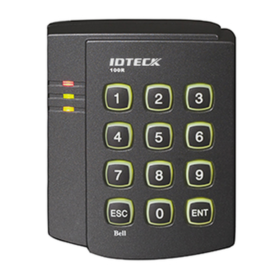
Page 14: Front Panel Description
Front Panel Description... -
Page 15: Identifying Supplied Parts
Identifying Supplied Parts Please unpack and check the contents of the box. -
Page 16: Installation
Installation 1. Tear off page template in the back of this manual and use the provided template to drill two 6-32 holes and one 1/2" hole on the proper location of the wall to mount the Wall Mount bracket as shown below. (If the gang box is already installed on the wall then skip this step.) 2. - Page 17 Before mounting the STAR 100R unit to the Wall Mount bracket, operational testi ng of the unit should be completed, as the locking pins will lock the unit to the Wa ll Mount. Removing the unit from the Wall Mount bracket after they have been ins talled together may cause damages to the bracket and render its effectiveness.
-
Page 18: Wiring Color Table
Wiring Color Table I/O PORT NAME SIGNAL NAME COLOR CODED 2PIN (J1) DC +12V Main Power(+12V) Black Power Ground 10PIN (J2) NC(1) Blue with White Stripe Door Relay(NC) COM(1) Gray with Red Stripe Door Relay(COM) NO(1) White with Red Stripe Door Relay(NO) NC(2) Purple with White Stripe... - Page 19 Ground Optional: Wiegand Output Function The default output format of 100R/IP100R is TTL and Chime Bell output. But, you can config ure the 100R/IP100R to generate output in Wiegand format and use it like a reader. (The 100R/IP100R can output data from card reading, but can’t output data from keypad in put.)
- Page 20 When the Wiegand Output function is used, TTL Output wire is changed to Wiega nd Data 0 and Chime Bell Output wire to Wiegand Data 1 Output wire. Therefore, you can’t use those functions. In addition, because TTL Output wire is changed to Wiegand Data 0 Output, you can’t initialize the 100W/IP100W using the wires.
-
Page 21: System Wiring For Typical Application
System Wiring for Typical Application Power Connection p.15... -
Page 22: Door Lock Connection
Connect (+) wire of DC +12V power to Red wire. ● Connect Power GND (-) wire of DC +12V to Black wire. ● Door Lock Connection Connection of POWER FAIL SAFE: Door Lock Connect Door RELAY (COM), Grey with Red stripe wire to DC +12V (be sure that the exi ●... -
Page 23: Door Contact Sensor Connection
Connect the other wire of Exit Button to Power GND (-) wire. ● (If a normally closed Exit button is used, then see section 12-55 to change the detection scheme from the defaulted setting) Door Contact Sensor Connection Connect Door Contact sensor (COM) wire to Door Contact Input, Yellow with Red stripe ●... -
Page 24: Wiegand Input Connection From Another Compatible Wiegand Reader (Separate Purchase Required)
● Plug in 9-pin connector to COM1 or COM2 Port of Personal Computer. ● Install and run STAR 100R Application Software. ● Chime Bell Connection (Separate purchase required) Connect (+) wire of Chime Bell unit to Bell Output, Brown with White stripe wire of Mai ●... -
Page 25: Initial Setup
Initial Setup The Flash memory of each shipped STAR 100R contains a minimum set of defaulted values, but it does not have any other preprogrammed values or user’s data in it, therefore, Initial Se tup is required upon the first time the unit is powered-up in order to operate the unit proper Registration of RF Cards for RF CARD ONLY MODE 1. -
Page 26: Registration Of Rf Cards With Pins For Rf Card + Pin Mode
4. The first card read becomes the Configuration Card and the following RF Cards are regi stered as User Access Cards. Once all User Access Cards have been registered, present t he Configuration Card again to complete the registration. (Please keep the Configurati on Card in a secure location for future changes.) 5. -
Page 27: Registration Of Rf/Pin Combination Mode
1. Apply 12V DC to the unit. All 3 LEDs will be flashing along with a powered-up melody (do mi sol me do do mi sol do~). 2. Press from the keypad. (PIN ONLY MODE) 3. Enter to register Configuration PIN then to registe r for each subsequent User Access PIN at a time and then enter the (Configuration PIN) to complete the registration. -
Page 28: Factory Defaulted Setting Values
Factory Defaulted Setting Values After the Initial Setup, the Main Unit uses the factory defaulted setting values below to exec ute the normal operation mode. You may want to change these factory setting values or mo dify your User Access list; refer to section 12 for instructions on how to customize the operat ion of your unit. - Page 29 (16) Unlock followed by Door Contact: Disable Factory Defaulted Setting Values p.23...
-
Page 30: Operation
Operation Normal Operation Mode (Safe Mode) When the Main Unit operates in normal mode, the yellow LED is flashing every second. Open the Door When a registered Card (or PIN) is read, the Door will open for 3 seconds along with the"do -mi-sol-do"... -
Page 31: Exit (Open The Door)
Exit (Open the Door) To request for exit from the inside, an Exit Button can be used to open the door for the sam e duration as in 11-2. Action and Alarm Caused by Unregistered Card (or PI When an unregistered Card (or PIN) is read, thus, access is denied and the Alarm can be acti vated for 2 seconds along with "sol-do-sol-do"... -
Page 32: Duress Alarm
The Secure Mode will revert back to the normal mode when a registered card (or PIN) is pres ented / entered. DURESS Alarm In case of Duress, enter the 2 digit Duress Password and the door will open as usual; howev er, the Duress Alarm (TTL Output) will activate an external Auto-Dialer to notify the appropri ate personnel. -
Page 33: Setting Changes
Setting Changes Configuration Card/PIN is required to change existing or defaulted setting values or to mana ge user’s access. First, present the Configuration Card (or enter the Configuration PIN) and e nter the 2-digit command code. Summary Table of Commands Command Action/Change setting values Add User Access Cards (RF CARD ONLY MODE) Add User Access Cards and PIN (RF CARD + PIN MODE) - Page 34 Add User Access Card/PIN (RF/PIN Combination Mode) Change Door open time when User Access Card (or PIN) is granted Change Alarm time when User Access Card (or PIN) is denied Change Alarm time when Try-Out error detected Change Alarm time when Door-Contact error detected Change Alarm time when Aux Input #1 detected Change Alarm time when Aux Input #2 detected Change Alarm time when Aux Input #3 detected...
- Page 35 Test Alarm time set by command "26" Test Alarm time set by command "27" Change Chime Bell activating time Open door unconditionally Close door unconditionally Enable QUICK ACCESS MODE Disable QUICK ACCESS MODE Enable Toggle Mode for Lock control Disable Toggle Mode for Lock control Enable Unlock followed by Door Contact Disable Unlock followed by Door Contact Disable Melody sound (turning off both the melody &...
- Page 36 Set Aux Input #1 Detection from ‘H’ to ‘L’ Set Aux Input #2 Detection from ‘L’ to ‘H’ Set Aux Input #2 Detection from ‘H’ to ‘L’ Set Aux Input #3 Detection from ‘L’ to ‘H’ Set Aux Input #3 Detection from ‘H’ to ‘L’ Set Exit Button Input Detection from ‘L’...
-
Page 37: 11. Add User Access Cards (Rf Card Only Mode)
Set delay time to activate SECURE MODE Set Door Open time-out for Door-Contact sensor Set number of times of Try-Out Set input key press time-out time Set Tamper Alarm output port Enable Tamper Alarm Disable Tamper Alarm Re-Initialize and erase all setup data 11. -
Page 38: 12. Add User Access Cards (Rf Card + Pin Mode)
12. Add User Access Cards (RF CARD + PIN MODE) 13. Add User Access PIN (PIN ONLY MODE) 14.1. Delete User Access Cards (RF CARD ONLY MOD E & RF CARD + PIN MODE) p.32 Setting Changes... -
Page 39: 14.2. Delete User Access Pin (Pin Only Mode)
14.2. Delete User Access PIN (PIN ONLY MODE) 15. Add User Access Card/PIN (RF/PIN Combination M ode) Configuration Card Command PIN PIN Configuration Card Symbol Setting Values Examples/Remarks Output (You must add value ① and ②) EX1)Activate Door Relay Mode In Safe &... -
Page 40: 21. Change Door Open Time When User Access Card (Or Pin) Is Granted
Symbol Setting Values Examples/Remarks from 01sec. to 99sec. no operation. PW is the 2 digits Password for Do not use ‘77’ for PW as it is Duress Alarm. used for Secure Mode mm is activating time value (minutes) mm value 00min. means from 01min. -
Page 41: 23. Change Alarm Time When Try-Out Error Detected
23. Change Alarm Time When Try-Out Error Detected (Refer to Table 1 for OM, tt=00~99 sec., Defaulted Alarm time = 10 sec.) 24. Change Alarm Time When Door Contact Error Det ected (Refer to Table 1 for OM, tt=00~99 sec.) Door Open Time-out setting is required for activating, refer to 12.81. -
Page 42: 26. Change Alarm Time When Aux Input #2 Detected
26. Change Alarm Time When AUX Input #2 Detected 27. Change Alarm Time When AUX Input #3 Detected (Refer to Table 1 for OM, tt=00~99 sec.) 28. Register 2 Digit Duress Alarm Password ‘00’ is registered as default Password. p.36 Setting Changes... -
Page 43: 29. Change Alarm Time When Duress Alarm Detected
29. Change Alarm Time When Duress Alarm Detected 30. Test Door Open Time Set by Command "21" 31. Test Alarm Time Set By Command "22" 32. Test Alarm Time Set By Command "23" 33. Test Alarm Time Set By Command "24" 34. -
Page 44: 35. Test Alarm Time Set By Command "26
35. Test Alarm Time Set By Command "26" 36. Test Alarm Time Set By Command "27" 37. Change Chime Bell Activating Time 38. Open Door Unconditional p.38 Setting Changes... -
Page 45: 39. Close Door Unconditional
39. Close Door Unconditional 40. Enable QUICK ACCESS MODE When QUICK ACCESS MODE is enabled, Door will open simply by press key. 41. Disable QUICK ACCESS MODE 42. Enable Toggle Mode for Lock Control If you set Enable Toggle Mode, Door will be toggled open and close function when the regis tered card or PIN entered. -
Page 46: 43. Disable Toggle Mode For Lock Control
43. Disable Toggle Mode for Lock Control 44. Enable Lock followed by Door Contact If you set Enable Lock followed by Door Contact, Door only be locked followed by Door Con tact so the door will remain open until the door is completely closed. 45. -
Page 47: 46. Disable Melody Sound
46. Disable Melody Sound 47. Enable Melody Sound 48. Change Keypad Lock-out Time When Try-Out Erro r Detected 49. Set AUX Input #1 Detection from ‘L’ to ‘H’ AUX#1 input is detected on the raising edge of AUX#1 input 49. Set AUX Input #1 Detection from ‘L’ to ‘H’ p.41... -
Page 48: 50. Set Aux Input #1 Detection From 'H' To 'L
50. Set AUX Input #1 Detection from ‘H’ to ‘L’ AUX#1 input is detected on the falling edge of AUX#1 input (Defaulted setting) Set AUX#2 Input Detection from ‘H’ to ‘L’ AUX#2 input is detected on the falling edge of AUX#2 input (Defaulted setting) 53. -
Page 49: 55. Set Exit Button Input Detection From 'L' To 'H
55. Set Exit Button Input Detection from ‘L’ to ‘H’ Exit Button input is detected on the raising edge of Exit Button input 56. Set Exit Button Input Detection from ‘H’ to ‘L’ Exit Button input is detected on the falling edge of Exit Button input (Defaulted setting) 57. -
Page 50: 59. Activate Ttl Output To 'H
59. Activate TTL Output to ‘H’ TTL output changes the state from logic '0' to logic '1' when it activates. 60. Activate TTL Output to ‘L’ TTL output changes the state from logic '1' to logic '0' when it activates. (Defaulted setting) 61. -
Page 51: 63. Enable Chime Bell Output
63. Enable Chime Bell Output 64. Disable Chime Bell Output 65. Set Delay Time to Activate SECURE MODE 66. Set Door Open Time-out for Door Contact Sensor 66. Set Door Open Time-out for Door Contact Sensor p.45... -
Page 52: 67. Set Number Of Times Of Try-Out
67. Set Number of Times of Try-Out 68. Set Input Keypress Time-out Time 69. Set Tamper Alarm Output Port p.46 Setting Changes... -
Page 53: 70. Enable Tamper Alarm
70. Enable Tamper Alarm To comply with UL 294, the Standard for Access Control System Units, the Tamper Alarm m ust be enabled. 71. Disable Tamper Alarm 72. Re-Initialize and Erase All Setup Data Please use this command when you really want to erase all data and start the unit from the beginning. -
Page 54: Initialization
Initialization When you lost the Configuration Card or forget the Master PIN number, you may need to re -initialize the unit for new setup. There is a hard-wired Initialize function on the unit. You may lose all setup data after Initialization. Hardware Initialization (When the master card or ID is lost) 1. -
Page 55: Wire Initialization
Wire Initialization (When the master card or ID is lost, 100R: Over V5.0.0 / IP100R: Over V2.0.0) 1. Main power off. 2. Connect the Green and orange with white stripe wire together and power on. 3. 3 color LED blinking with beep sound indicates the success of initialization. -
Page 56: Fcc Registration Information
FCC REGISTRATION INFORMATION FCC Requirements Part 15 Caution: Any changes or modifications in construction of this device which are not expressly approved by the responsible for compliance could void the user's authority to operate the e quipment. NOTE: This device complies with Part 15 of the FCC rules. Operation is subject to the following two conditions;... -
Page 57: Troubleshooting
[Operation] Problem When power is first supplied, 3 LEDs of 100R blinks only and an RF card doesn’t recognize. Cause 1. System initialization Status (Unregistered Master Card (or PIN)) 2. System malfunction/data damaged or lost due to an external noise or a short circuit. -
Page 58: Problem
Upon initialization, all data default value will be restored. If the problem still persists, contact our customer service center. Problem The 100R operates suddenly on general mode during setting or registering a user on mode s election. Cause Over standby time on mode selection Solution If not entering a key or a card within 20 sec. -
Page 59: Registering Or Deletion]
● Solution Make sure that installation and operation are normal. ☞ When installing the 100R first or When finishing system initialization#1). Because system is the status of initialization, register mode selection, master card (or PIN) an d user. 1. 100R Mode Selection: Mode Number + ENT... -
Page 60: Problem
RF or PIN 15 + ENT 3. By modes, enter a user card, PIN and password. 4. Enter the master card (or PIN: 4 to 6digit (mode 03 or 05) + ENT). See “Initial Setting” to register master or user. If the problem still persists, contact our customer service center. Problem User card or PIN cannot be deleted. -
Page 61: Loosing A Master Card Or Pin
When loosing a master card or PIN, if you change product’s settings, you should initialize the product. ☞ In system initialization, master, user and system settings are changed by initials. ☞ System Initialization by product’s versions 100R V5.0.0 under or IP100R V2.0.0 under 1. After power is off, separate product from wall. [System Initialization] p.55... -
Page 62: 100R V5.0.0 Over Or Ip100R V2.0.0 Over
Make sure to consult a technician before separating or initializing a product. If the problem still persists, contact our customer service center. [Communication] Problem Although the 100R connects with PC, communication was not at all. Cause Setup malfunction of communication environment ●... -
Page 63: Solution
If the problem still persists, contact our customer service center. [Keypad] Problem An RF card works properly but the 100R cannot recognize the RF card number when it is ent ered in the keypad. Cause An error in system settings ●... -
Page 64: Solution
2. Although it goes on definite time, buzzer doesn’t go off continuously. Initialize the product. If the problem still persists, contact our customer service center. [External Device] Problem An exit button doesn’t work. Cause An error in connection between the exit button and the 100R ● p.58 Troubleshooting... -
Page 65: Solution
Internal circuit element damaged or malfunctioning ● Solution Make sure of connection between the exit button and the 100R and of operation of exit but ton. ☞ Check the connection between the exit button and the 100R. Make sure to use a NO (Normal Open)-type exit button. -
Page 66: Problem
System malfunction/data damaged or lost due to an external noise or a short circuit ● Solution Make sure of connection between the exit button and the 100R and of operation of exit rea ☞ Check the connection between the exit button and the 100R. p.60... -
Page 67: Problem
If the problem still persists, contact our customer service center. Problem A door lock doesn’t work. Cause An error in connection between the door lock and the 100R ● A door lock error ● System malfunction/data damaged or lost due to an external noise or a short circuit ●... -
Page 68: Solution
Solution Check the connection between the door lock and the 100R. The connection between a door lock and the 100R may vary depending on the do or lock type and its operation type (Normal Open, Normal Close). If this does not solve the problem, proceed with the following steps. - Page 69 ☞ Check the door lock operation and the connection between the door lock and the 100R. 1. Check the condition of the connection cable (a short circuit or cut) between the door lo ck and the 100R. 2. Check the door lock operation.
-
Page 70: Template
Template p.64... -
Page 71: Rma Request
RMA Request If you have any questions or problems regarding the RMA services, please contact us using t he contact information below. Friendly representatives at IDTECK are always standing by to provide the best after sales services. IDTECK Headquarter 5F, Ace Techno Tower B/D, 684-1, Deungchon-Dong,...
Need help?
Do you have a question about the 100R and is the answer not in the manual?
Questions and answers