IDTECK Star iCON100 Quick Installation Manual
Hide thumbs
Also See for Star iCON100:
- User manual (44 pages) ,
- Quick installation manual (20 pages) ,
- Quick install manual (5 pages)
Advertisement
Table of Contents
- 1 Important Safety Instructions
- 2 What's Included
- 3 Board Layout
- 4 Installation Tips & Check Point
- 5 Check Points before Installation
- 6 Check Points During Installation
- 7 Installation of the Product
- 8 System Initialization of Icon100
- 9 Device Setting
- 10 RS232 Communication Port Connection
- 11 RS-422 Communication Port Connection
- 12 TCP/IP Communication Port Connection (Optional)
- 13 TCP/IP Converter (External Version)
- 14 Initialization of Icon100
- Download this manual
See also:
User Manual
Advertisement
Table of Contents

Related Manuals for IDTECK Star iCON100


Summary of Contents for IDTECK Star iCON100
- Page 1 Quick Installation Guide Access Controller...
-
Page 2: Important Safety Instructions
※ iCON100/iCON100-SR QUICK INSTALLATION GUIDE 1. IMPORTANT SAFETY INSTRUCTIONS The description below is to keep user’s safety and prevent any product damage. Please fully read these instructions and use the product properly. Danger: This symbol indicates that incorrect handling of the product may result in serious injury or death. -
Page 3: What's Included
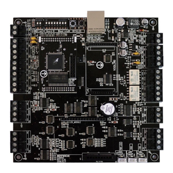
※ iCON100/iCON100-SR QUICK INSTALLATION GUIDE 2. WHAT’S INCLUDED Please unpack and check the contents of the box. If any of these parts are missing, please contact a nearby distributor or IDTECK. Main Unit User’s Manual Diode Register ( 1ea ) - Page 4 ※ iCON100/iCON100-SR QUICK INSTALLATION GUIDE These switches are to set board ID and baud rate to communicate with PC. (#1~#5 DIP switches for board ID, #6~#8 DIP switches for baud rate) ○ Initialization Switches These switches are to initialize user data in the memory. To be default setting by Initialization, press the two switches simultaneously then keep pressing more than 2 seconds to initialize properly.
- Page 5 ※ iCON100/iCON100-SR QUICK INSTALLATION GUIDE ○ 21 TTL #1 This is the TTL #1 output port. ○ 22 TTL #2 This is TTL #2 output port. ○ 23 Relay #1 This is the relay #1 output port. ○ 24 Relay #2 This is the relay #2 output port.
-
Page 6: Installation Tips & Check Point
※ iCON100/iCON100-SR QUICK INSTALLATION GUIDE 4. INSTALLATION TIPS & CHECK POINT 4.1 Check Points before Installation 4.1.1 Selection of Cable System installation cabling will be configured as follow. Door Lock Door Lock Exit Button Exit Button Figure: System Installation Layout... - Page 7 ※ iCON100/iCON100-SR QUICK INSTALLATION GUIDE 4.1.2 Recommended Cable Type and Permissible Length of Cable Maximum Reference Description Cable Specification Distance Power (DC12V) Belden #9409, 18 AWG ① DC Power -> iCON100 2 conductor, unshielded Belden #9512, 22 AWG 4 conductor, shielded Reader (Power and Data) 150m ②...
-
Page 8: Check Points During Installation
※ iCON100/iCON100-SR QUICK INSTALLATION GUIDE 4.2 Check Points during Installation 4.2.1 Termination Resistor Termination resistors are used to match impedance of the network to the impedance of the transmission line being used. When impedance is mismatched, the transmitted signal is not completely absorbed by the receiver and a portion of signal is reflected back into the transmission line. - Page 9 ※ iCON100/iCON100-SR QUICK INSTALLATION GUIDE 3) Power Ground The most important point for grounding system is not to connect both ends of shield wires to the grounding system; in this case there will be a current flow through the shield wire when the voltage level of both ends of shield wire is not equal and this current flow will create noise and interfere to communications.
-
Page 10: Installation Of The Product
※ iCON100/iCON100-SR QUICK INSTALLATION GUIDE 5. INSTALLATION OF THE PRODUCT 5.1 Dimension (Unit: inch (mm)) 3.1(77) 5.4(137) Figure: iCON100 Dimension Figure: LCD Module Dimension 3.1(77) 7.9(200) Figure: Keypad Dimension 5.2 System Initialization of iCON100 Initialization must be performed before first installation of iCON100. Press down the two initialization switches simultaneously then keep pressing more than 2 seconds. -
Page 11: Device Setting
※ iCON100/iCON100-SR QUICK INSTALLATION GUIDE 5.3 Device Setting 5.3.1 26Bit / 34Bit Wiegand Setting Select the data format (26bit/34bit) input to reader port. There is a switch for bit setting on the upper left side of iCON100 board. The switch is set to ‘OFF’ position as the default (26Bit Wiegand setting). If the switch is set to ‘ON’... - Page 12 ※ iCON100/iCON100-SR QUICK INSTALLATION GUIDE 5.3.2 Board ID(Communication ID) Setting Board ID is the unique address to communicate with PC. There is 5 channel DIP switch on the upper left side of the iCON100 board for board ID setting. Each DIP switch has assigned address value and the board ID is calculated by the sum value of each switch set to “ON”...
- Page 13 ※ iCON100/iCON100-SR QUICK INSTALLATION GUIDE 5.3.3 Baud Rate Setting Baud rate is the speed rate during communication with host PC. The 3 DIP switches are assigned for baud rate setting on the upper left side of the iCON100 board. You can select one of 4800bps, 9600bps, 19200bps, 38400bps, 57600bps and 115200bps.You have to set applicable baud rate according to communication environment, and the connected devices on one loop must have the same baud rate.
- Page 14 ※ iCON100/iCON100-SR QUICK INSTALLATION GUIDE - Connect one wire from a Door Contact Sensor to Input #2 - Connect the other wire from the Door Contact Sensor to GND Auxiliary Input Connection (Applied to Input #3, Input #4 and Input #5) - Connect one wire from an Auxiliary Input Device to one of the Input #3, #4 and #5.
- Page 15 ※ iCON100/iCON100-SR QUICK INSTALLATION GUIDE Alarm Device Connection (Relay #2) - Connect COM port of Relay #2 to DC+12V - Connect NO port of Relay #2 to (+) wire of Alarm devices - Connect GND port to (-) wire of Alarm devices Figure: Door Lock, Al arm Device Connection Caution: You need to connect the diode ( 1N4001 ~ 1N4007 or Similar) when connecting external devices to...
-
Page 16: Rs232 Communication Port Connection
※ iCON100/iCON100-SR QUICK INSTALLATION GUIDE 5.4.5 Optional Accessory Connections Keypad and LCD Display Connection Connect the Keypad and LCD Display to the Keypad and LCD ports as shown on below. You should turn off the power when connecting. Figure: Keypad and LCD Connection with iCON100 6. -
Page 17: Rs-422 Communication Port Connection
※ iCON100/iCON100-SR QUICK INSTALLATION GUIDE 6.2 RS-422 Communication Port Connection 6.2.1 RS-422 Connection (Single iCON100 Connection) An RS422/RS232 converter is required to use RS422 communication between the iCON100 and the PC. CAUTION: The INC400 converter is recommended for stable communication when the distance between the converter and the device is too far. - Page 18 ※ iCON100/iCON100-SR QUICK INSTALLATION GUIDE 6.2.2 RS-422 Connection (Multiple iCON100 Connections) RS422/RS232 converter is required to use RS422 communication between multiple iCON100s and a host computer. Please follow the following instructions. First, you have to connect all RS422 port of all iCON100s in parallel. - Connect RS422-TX(-) of one iCON100 to RS422-TX(-) of another iCON100.
-
Page 19: Tcp/Ip Communication Port Connection (Optional)
※ iCON100/iCON100-SR QUICK INSTALLATION GUIDE 6.3 TCP/IP Communication Port Connection (optional) 6.3.1 How to Connect TCP/IP Module to iCON100 1) As below figure, Insert TCP/IP module (IIM7100A) to iCON100 in right direction. Direction of arrows have to be matched between iCON100 ( ) and TCP/IP ( ) module. - Page 20 ※ iCON100/iCON100-SR QUICK INSTALLATION GUIDE 6.3.1.1 TCP/IP Module (IIM7100A) Setting To do TCP/IP communication through TCP/IP Module(IIM7100) on the iTDC/iTDC-SR board, use TCP/IP Module(IIM7100) setting program(IIM100A Configuration Tool) to set information for Network and Serial communication. 1. Install TCP/IP Module(IIM7100) setting program,IIM100A Configuration Tool. The Program to set network and check operation status is contained in Application software (iTDC PRO I, II, STARWATCH STANDARD) CD.
- Page 21 ※ iCON100/iCON100-SR QUICK INSTALLATION GUIDE 3) All TCP/IP Modules connected on network is displayed. In the ‘Board List’, MAC address of TCP /IP Module is displayed. 4) Check MAC address of TCP/IP Module (described on TCP/IP module) and then select it. Setting information is displayed as below.
- Page 22 ※ iCON100/iCON100-SR QUICK INSTALLATION GUIDE Column Name Setting Value Speed 9600 DataBit Parity None Stop Bit Flow CTS/RTS 7) Select ‘Option’ tab. Select option values (‘Inactivity Time’, ‘Time’, ‘Size’ and ‘Char’ ) of selected TCP/IP module. Select ‘30000’ for ‘Inactivity Time’, ‘0’ for ‘Time’, ‘0’ for ‘Size’, ‘00’ for ‘Char’. Refer to table below. Column Name Setting Value Inactivity Time...
-
Page 23: Tcp/Ip Converter (External Version)
※ iCON100/iCON100-SR QUICK INSTALLATION GUIDE 6.3.2 How to wire TCP/IP Communication Optional TCP/IP module is required for TCP/IP communication between the iCON100 and the PC. Please follow the instructions below; 1. Connect the LAN cable of the network system to the RJ45 jack of the iCON100. 2. - Page 24 ※ iCON100/iCON100-SR QUICK INSTALLATION GUIDE PRESS SYSTEM INIT. WAITING !!! Figure: Switch Location Figure: Magnification of Switch Figure: LCD Display Caution If the Controller is initialized, all ID information and event data stored in the Controller will be cleared. Therefore, the Initialization should be performed by authorized person only. It is strongly recommended to upload all ID information and events data before initialization.
Need help?
Do you have a question about the Star iCON100 and is the answer not in the manual?
Questions and answers