IDTECK Star LX505 User Manual
Proximity / pin access controller
Hide thumbs
Also See for Star LX505:
- User manual (90 pages) ,
- User manual (78 pages) ,
- User manual (78 pages)
Table of Contents
Advertisement
Quick Links
Download this manual
See also:
User Manual
Advertisement
Table of Contents

Related Manuals for IDTECK Star LX505


Summary of Contents for IDTECK Star LX505
- Page 1 User’s Manual Proximity / PIN Access Controller...
-
Page 2: Table Of Contents
Table of Contents 1. IMPORTANT SAFETY INSTRUCTIONS ..............5 2. GENERAL........................6 3. FEATURES ......................6 4. SPECIFICATION ......................7 5. IDENTIFYING SUPPLIED PARTS ................8 6. PRODUCT OVERVIEW .....................9 6.1 F ............................9 EATURES 6.2 P ......................... 11 RODUCT XPLANATION 6.2.1 Panel Description.....................11 6.2.2 Connection Layout...................11 6.2.3 Color Coded &... - Page 3 10.5 ID REGISTRATION ........................26 11. OPERATIONS .......................29 11.1 N ........................29 ORMAL PERATION 11.2 D ........................29 EFAULT ETTING 12. SETTING CHANGES ....................30 12.1 F1 SETUP MENU ........................31 12.1.1 Language......................32 12.1.2 Date and Time Setting..................32 12.1.3 Reader #1 Mode....................32 12.1.4 Reader #2 Mode....................33 12.1.5 Reader #1 PIN Input..................33 12.1.6 Reader #2 PIN Input..................33...
- Page 4 12.6.3 Output Setting for Reader#1 ID OK Level 3 ............52 12.6.4 Output Setting for Reader#1 ID OK Level 4 ............52 12.6.5 Output Setting for Reader#1 ID Error ...............52 12.6.6 Output Setting for Reader#1 T/S Error .............52 12.6.7 Output Setting for Reader#1 APB Error ............52 12.6.8 Output Setting for Reader#2 ID OK Level 1 ............52 12.6.9 Output Setting for Reader#2 ID OK Level 2 ............52 12.6.10 Output Setting for Reader#2 ID OK Level 3.............52...
-
Page 5: Important Safety Instructions
1. Important Safety Instructions When using Proximity / PIN Access Controller, you are recommended to follow the basic safety precautions below to reduce the risk of fire, electrical shock, and injury to persons. Fully read and understand all instructions and follow them completely. Follow all warnings and instructions marked on the product. -
Page 6: General
The Star LX505 / IDTECK LX505SR has 2 relay outputs to control a door lock and an alarm relay that is used to warn any error. The graphic LCD supports multiple languages so that the unit can be operated anywhere in the world. -
Page 7: Specification
• 2 Men Operation Mode • Duress Alarm Function • Multiple Master IDs Registration • Graphic LCD of Multi Languages Display • Voice Guide Programmable for Other Language • Voice announcement Programmable by user via serial communication • Door Phone Function (Optional) •... -
Page 8: Identifying Supplied Parts
UL, FCC, CE, MIC 5. Identifying Supplied Parts Please unpack and check the contents of the box. If any of these parts are missing, please contact a near-by distributor or IDTECK as soon as possible. Cable & User’s Main Unit... -
Page 9: Product Overview
PC. Keypad If the Star LX505 / IDTECK LX505SR is not connected to a host PC, the built-in keypad and LCD module can be used for the entire operations and configuration process. - Page 10 Two Men Operation This feature is to set the Star LX505 / IDTECK LX505SR to allow a certain user (e.g. a visitor) to pass the door only when that user is accompanied by another special user (e.g. a guider.) Both of the visitor and the guide should be authorized together for the door to be opened.
-
Page 11: Product Explanation
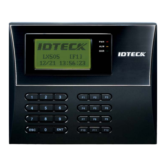
6.2 Product Explanation 6.2.1 Panel Description LCD Display System Operation Status LED 24-key keypad (incl. 12 function keys) Figure: Description of LX505 Front Panel • LCD Module: The LCD screen displays the status of the LX505. • System Operation Status LED: When the power is applied to the LX505, the red LED is turned on. -
Page 12: Color Coded & Wring Table
6.2.3 Color Coded & Wring Table SIGNAL I/O PORT NAME WIRE COLOR NAME CNN-1(2PIN CONNECTOR) Main Power (+12V) DC 12V Power Ground GND 0V Black CNN-5 (5PIN CONNECTOR) RS485-RTX(+) RS485-A(+) Yellow wire RS485-RTX(-) RS485-B(-) Gray wire RS232-TX Black wire with White stripe RS232-RX Red wire with White stripe RS232-GND... -
Page 13: Installation Tips & Check Point
7. Installation Tips & Check Point 7.1 Check Points before Installation 7.1.1 Selection of Cable The system installation cables should be connected as follows; Figure: System Installation Layout... -
Page 14: Recommended Cable Type And Permissible Length
7.1.2 Recommended Cable Type and Permissible Length Cable Maximum Reference Description Specification Distance Belden #9409, LX505 Power (DC12V) 18 AWG DC Power -> LX505 2 conductor, unshielded Belden #9512, 22 AWG Reader 4 conductor, shielded (Power and Data) 150m Belden #9514, Exit Reader ->... -
Page 15: How To Connect Termination Resistors
be used for termination resistor in parallel between the receiver lines “A” and “B” for 2 wires RS485 system. A termination resistor of less than 90Ω should not be used and no more than 2 terminations should be used in one network system. 7.2.2 How to Connect Termination Resistors Figure: Termination resistors for 2 wire RS485 communication system 7.2.3 Grounding System for Communication Cable... -
Page 16: Reverse Diode Connection
7.2.4 Reverse Diode Connection If you connect an inductor (Door Locks or Alarm device) to the output relays, there will be a high surge voltage created while the inductor is turning on and off. If you do not connect a reverse diode, the surge voltage will transfer and damage the electronic circuit of the controller. -
Page 17: System Initialization (External Reader Port)
1:Yes”. Press <1> key if you want to initialize the system. After all the initialization process is completed, the system will be operating on the normal mode and the LCD will display “IDTECK, LX505 [F1], Date Time”. Press and hold the Power ON initialization button. - Page 18 Door Contact Sensor Connection Connect one wire from Door Contact Sensor to Yellow wire with Red stripe. Connect the other wire from Door Contact Sensor to GND. Auxiliary Input Connection Applicable to Aux Input #1(Green wire), Aux Input #2(Green wire with white stripe) Connect one wire from Auxiliary Input Device to one of Aux Input #1 or Aux Input #2.
-
Page 19: Output Connection
8.4.3 Output Connection Door Lock (Power Fail Safe) Connection (Door Relay) Connect COM wire of Door Relay, White wire with red stripe to +12V. Connect NC wire of Door Relay, Blue wire with white stripe to (+) wire of Door Lock. Connect GND wire to (-) wire of Door Lock. -
Page 20: Communication
• Compatible Readers (External Reader): Star LX505: Standard 26bit Wiegand Format Proximity Readers Standard 26bit Wiegand + 8bit Burst Format Proximity and keypad Reader IDTECK LX505SR: Standard 34bit Wiegand Format Proximity Reader Standard 34bit Wiegand + 8bit Burst Format Proximity and keypad Reader •... -
Page 21: Rs485 Communication Port Connection
Figure: RS232 COMMUNICATON 9.2 RS485 Communication Port Connection 9.2.1 RS485 Connection (Standalone Unit) An RS485/RS232 converter is required to use the RS485 communication between the LX505 and a host PC. Please follow the steps below. Connect RS485-RTX (+), Yellow wire to RS485-A port of the converter. Connect RS485-RTX (-), Gray wire to RS485-B port of the converter. -
Page 22: Rs485 Connection (Multiple Units)
9.2.2 RS485 Connection (Multiple Units) An RS485/RS232 converter is required to use RS485 communication between multiple LX505 and a host PC. Please follow the instructions below. First, connect all RS485 port of the LX505 units in parallel. (max of 32 LX505 Units can be connected) Connect RS485-RTX (+) (the Yellow wire) of one LX505 to RS485-RTX (+) (the Yellow wire) of another LX505. -
Page 23: Tcp/Ip Communication Port Connection (Optional)
9.3 TCP/IP Communication Port Connection (Optional) An optional TCP/IP Module is required for TCP/IP communication to the host PC. Follow the next instruction. Connect RJ45 plug, LAN cable of the network system to RJ45 jack of the LX505. If you install multiple LX505s and only one TCP/IP port is available, you may connect one LX505 to TCP/IP and then connect all the LX505s using the RS485 multiple communication as shown in the below figure. -
Page 24: Basic Setting
1:Yes”. Press <1> key if you want to initialize the system. After all the initialization process is completed, the system will be operating on the normal mode and the LCD will display “IDTECK, LX505 [F1], Date Time”. Press and hold the Power ON initialization button. -
Page 25: How To Enter The Setup Menu
10.2 How to Enter the SETUP MENU To set up the LX505 or to change the settings, you have to enter the SETUP MENU first. To do so, press <0> key eight (or ten) times and <ENT> key on the keypad. (The Default Master ID is ‘00000000’. -
Page 26: Date / Time Setting
10.4 DATE / TIME SETTING Select [SET DATE/TIME] in the [F1 SETUP MENU] and enter the total of 15 digits (i.e. Year / Month / Date / Hour / Minute / Second / Day) as shown below. The LCD will display the new Date and Time after the time setting is completed but the year and day will not be displayed. - Page 27 b) Registration Using Keypad NOTE| In case you make a typing mistake during the registration process, you can press F1 button to erase your errors. Scanning – means the reader is waiting for an ID number to be entered. The card number for the card will appear with a beep sound when you present the card.
- Page 28 C – stands for the ID code. Code ‘0’ is default and code ‘1’ or ‘2’ is a code used for the TWO MEN MODE. Code ‘3’ is used for the ARM/DISARM function and code ‘4’ is assigned for lost cards. MA –...
-
Page 29: Operations
11. OPERATIONS 11.1 Normal Operation Power on When power is applied to the LX505, the Red LED is lit. Registered card reading When a registered card (or a PIN) is read (and his/her password is verified), the Door (Relay#1) will open for 3 seconds (Default) with the Green LED on. Exit Button When the Exit button is pressed, the Door (Relay#1) will open for 3 seconds with the Green LED on. -
Page 30: Setting Changes
12. Setting Changes INITIAL DISPLAY (MODEL NAME, CURRENT TIME) ID INPUT? F1 SETUP MENU F2 SETUP MENU MASTER ID F3 SETUP MENU /PW/FINGERPRINT ? NORMAL OPERATIONS MODE F4 SETUP MENU F5 SETUP MENU SETUP MODE F6 SETUP MENU F7 SETUP MENU F8 SETUP MENU F9 SETUP MENU To set up the LX505 or to change the settings, you have to enter the SETUP MENU first. -
Page 31: F1 Setup Menu
12.1 F1 SETUP MENU 3 Languages Supported + 1 Selectable KOREAN LANGUAGE ENGLISH CHINESE JAPANESE <4> or <6> KEY SPANISH PORTUGUESE ARABIC SET DATE/TIME Enter 15 digits for date and time <4> or <6> KEY ID ONLY(DEFAULT) READER#1 MODE ID+F/P (P/W) ID+P/W+F/P <4>... -
Page 32: Language
12.1.1 Language The default language is English. Supported languages include English, Spanish, Portuguese and one of Chinese, Korean, Japanese and Arabic (selectable). 12.1.2 Date and Time Setting e.g. 200302101330152 = Feb. 10, 2003, 13:30:15, Monday 12.1.3 Reader #1 Mode Note: READER#1 is the built-in proximity reader in the unit. ID(PIN) ONLY: In this mode, users can access the door by simply presenting their card or entering their ID number. -
Page 33: Reader #2 Mode
12.1.4 Reader #2 Mode The READER#2 MODE setting menu is the same as READER#1 MODE setting menu in the previous section. Note: READER#1 is the Exit Reader connected to the LX505. ID ONLY: In this mode, users can exit/enter the door by simply presenting their card or entering their ID number. -
Page 34: Baud Rate Setting
The default Communication Address is “000” Set different communication addresses for each unit in the loop. 12.1.8 Baud Rate Setting The LX505 supports different Baud Rates of 9600, 19200, 38400 and 57600bps. The recommended Baud Rate is 19200bps. An incorrect Baud Rate setting will result in communication errors. -
Page 35: F2 Setup Menu
12.2 F2 SETUP MENU EVENT MEMORY NOT USE USE(DEFAULT) <4> or <6> KEY ID DISPLAY MESSAGE(DEFAULT) ID+MESSAGE <4> or <6> KEY TIME UNIT UNIT: 1 SEC (DEFAULT) UNIT: 0.1 SEC <4> or <6> KEY OUTPUT T/S+ID NOT USE(DEFAULT) <4> or <6> KEY <4>... -
Page 36: Event Memory
12.2.1 Event Memory You can select whether to activate the event memory or not. If you set the event memory to USE, the LX505 generates an error message and keeps all event transactions stored in the memory. If you select NOT USE, however, the LX505 will not generate an error message and new events will be overwritten into the event buffers. -
Page 37: Output T/S + Id
This setting allows you to define the unit of time. 1sec: Output Time is calculated in the time unit of 1 second for the IN/OUT definition. 0.1sec: Output Time is calculated in the time unit of 1/10 second (or 100ms) for the IN/OUT definition e.g. -
Page 38: Duress Mode
The Anti-pass back feature is used to prevent an identical user from entering or exiting the door more than twice in a row. This mode can be applied only when an Exit Reader is installed. Do not set this mode to USE if an Exit Button is not installed. NOT USE: The Anti-pass back feature is disabled. -
Page 39: Door Open Alarm Time Setting
This feature allows you to use the LX505 as a reader (rather than as a controller). If this setting is set to USE, the LX505 sends 26bit Wiegand Output through two TTL output ports. NOT USE: Normal TTL outputs will be activated. USE: 26bit Wiegand outputs will be generated through TTL1 and TTL2 ports. -
Page 40: F3 Setup Menu
12.3 F3 SETUP MENU PRINT OUTPUT NOT USE(DEFAULT) AUTO PRINT <4> or <6> KEY MANUAL PRINT VOICE VOLUME 0(MUTE) - 4(MAXIMUM) <4> or <6> KEY ARM/DISARM Enter a 2-digit code <4> or <6> KEY <4> or <6> KEY TWO MEN MODE NOT USE(DEFAULT) <4>... -
Page 41: Voice Volume
12.3.2 Voice Volume The LX505 tells you its status out loud. You can adjust the volume of the voice from 0 (mute) to 4 (maximum). New voices can be downloaded through communications with the host PC. 12.3.3 Arm/Disarm This setting allows you to set the Arm Code and the Disarm Code. After setting the Arm Code or Disarm Code, you can set the LX505 to the ARM mode by entering the ARM code and presenting an ARM/DISARM card (i.e. -
Page 42: One Time Read
12.3.5 One Time Read If this mode is set to USE, an identical ID won’t be read twice within 30 seconds. 12.3.6 Max. User Setup You can select the maximum number of user registrations; 10,000 or 20,000. If the maximum number of registrants is set to 20,000, the maximum number of event transactions becomes 10,000. -
Page 43: F4 Setup Menu
12.4 F4 SETUP MENU T/S/ CODE: 01 - 10 TIME SCHEDULE Weekly : 8 DAYS, HOL, SUN, MON, … , SAT INTERVAL: 1- 10 <4> or <6> KEY H/S CODE: 01 - 10 HOLIDAY HOLIDAYS: 001 - 100 <4> or <6> KEY <4>... -
Page 44: Holiday
There are 10 Time Schedule Codes available for users. Time Schedule Code “00” is the default setting that allows access to all users at any time. The user can program the Time Schedule Codes 01 to 10. Each Time Schedule Code has 8 programmable days (i.e. Sun, Mon, Tue, Wed, Thu, Fri, Sat and Holiday) and each day has 5 Time Intervals (i.e. -
Page 45: Holiday Code
12.4.3 Holiday Code The Holiday Code setting allows you to link a Holiday Schedule to a Time Schedule. A Time Schedule has 5 Time Intervals for holidays and the Time Intervals are applied only to the dates of this Holiday Schedule. The default Holiday Schedule Code is ‘00’ which means no holidays are applied to the Time Schedule. -
Page 46: F5 Setup Menu
12.5 F5 SETUP MENU EXIT BUTTON Output operation time: 10 DIGITS DOOR CONTACT Output operation time: 10 DIGITS AUX INPUT #1 Output operation time: 10 DIGITS AUX INPUT #2 Output operation time: 10 DIGITS TAMPER ALARM Output operation time: 10 DIGITS CUT OFF ALARM Output operation time: 10 DIGITS DURESS ALARM... -
Page 47: Exit Button Output Setting
Default Output Settings for Input Sources Door Alarm TTL#1 TTL#2 Buzzer OUTPUT Relay Relay (T1) (T2) (BZ) (DR) (AR) [1] EXIT BUTTON [2] DOOR CONTACT [3] AUX Input #1 [4] AUX Input #2 [5] TAMPER ALARM [6] CUT OFF ALARM [7] DURESS ALARM [8] ARM/DISARM OUT [9] DR TIME OUT... -
Page 48: Door Contact Output Setting
12.5.2 Door Contact Output Setting 12.5.3 Aux Input#1 Output Setting 12.5.4 Aux Input#2 Output Setting 12.5.5 Tamper Alarm Output Setting 12.5.6 Cut Off Alarm Output Setting 12.5.7 Duress Alarm Output Setting 12.5.8 Arm/Disarm Output Setting 12.5.9 DR TIME Output Setting The rest of output activation time settings above can be configured in the same way as the Exit Button Output Setting in the section 12.6.1, which means you can refer to that section to get some idea as to how to do the configuration. -
Page 49: Cut Off Check Setting
You can assign a Time Schedule Code to each Input. The default Time Schedule Code for every input is “00”, which means no Time Schedule is applied to them. Changing these settings can be very useful when you want to activate PIR sensor input during a certain period of time. -
Page 50: F6 Setup Menu
12.6 F6 SETUP MENU RD1 ID OK LV1 Output operation time: 10 DIGITS RD1 ID OK LV2 Output operation time: 10 DIGITS RD1 ID OK LV3 Output operation time: 10 DIGITS RD1 ID OK LV4 Output operation time: 10 DIGITS RD1 ID ERROR Output operation time: 10 DIGITS RD1 T/S ERROR... -
Page 51: Output Setting For Reader#1 Id Ok Level 1
Default Output Setting for Different Inputs Door Alarm TTL#1 TTL#2 Buzzer OUTPUT Relay Relay (T1) (T2) (BZ) (DR) (AR) [1] Reader#1 ID OK LV1 [2] Reader#1 ID OK LV2 [3] Reader#1 ID OK LV3 [4] Reader#1 ID OK LV4 [5] Reader#1 ID Error [6] Reader#1 T/S Error [7] Reader#1 APB Error [8] Reader#2 ID OK LV1... -
Page 52: Output Setting For Reader#1 Id Ok Level 2
Output Time setting from 12.7.2 to 12.7.14 can be configured in the same way as 12.7.1 RD1 ID OK Level 1 Output setting. 12.6.2 Output Setting for Reader#1 ID OK Level 2 This output time is applied for the users registered with Level#2 output. 12.6.3 Output Setting for Reader#1 ID OK Level 3 This output time is applied for the users registered with Level#3 output. -
Page 53: Output Setting For Reader#2 Id Ok Level 4
12.6.11 Output Setting for Reader#2 ID OK Level 4 This Output Time is applied for the users registered with Level#4 output. 12.6.12 Output Setting for Reader#2 ID Error This output time is applied when a user that is not registered in Reader #1 attempts access. -
Page 54: F7 Setup Menu
12.7 F7 SETUP MENU ID REGISTRATION CARD <4> or <6> KEY ID DELETION CARD <4> or <6> KEY ID LIST REGISTERED IDs are displayed <4> or <6> KEY <4> or <6> KEY MASTER ID REG. NOT USE(DEFAULT) <4> or <6> KEY THE NUMBER OF REGISTERED IDs is ID COUNT displayed... - Page 55 b) Registration Using Keypad NOTE| In case you make a typing mistake during the registration process, you can press F1 button to erase your errors. Scanning – means the reader is waiting for an ID number to be entered. The card number for the card will appear with a beep sound when you present the card.
-
Page 56: Id Deletion
C – stands for the ID code. Code ‘0’ is default and code ‘1’ or ‘2’ is a code used for the TWO MEN MODE. Code ‘3’ is used for the ARM/DISARM function and code ‘4’ is assigned for lost cards. MA –... -
Page 57: Id List
12.7.3 ID List The LCD will display the 5-digit ID Index, 8-digit ID number, 4-digit Password, Timeschedule for Reader#1(TA) and Reader#2(TB), ID code(C), accessible Readers(RD), operating mode for Reader#1(MA) and Reader#2(MB), and the output level(LV). The “EMPTY” message will appear if there is no registered user ID. The “FIRST ID”... -
Page 58: Id Count
MASTER ID REGISTRATION BY PIN The default Master ID #01 is “00000000” without a password. For the LX505SR, it is ‘0000000000’. Up to 10 Master IDs (from “01” to “10”) can be stored in the LX505. 12.7.5 ID Count The number of registered user IDs is displayed. This count automatically increases or decreases as new IDs are registered or old IDs are deleted. -
Page 59: F8 Setup Menu
12.8 F8 SETUP MENU SYSTEM INITIAL <4> or <6> KEY EVENT CLEAR <4> or <6> KEY ID CLEAR <4> or <6> KEY <4> or <6> KEY MASTER ID CLR <4> or <6> KEY T/S CLEAR <4> or <6> KEY DEFAULT SET 12.8.1 System Initialize This operation is used to initialize the LX505 system. -
Page 60: Event Clear
12.8.2 Event Clear If the event memory is full or if you want to change the ID COUNT, you can clear the event memory here. Press <ENT> key first, then press <1> key to clear event memory or <0> key to cancel the operation. -
Page 61: Time Schedule Clear
9.8.5 TIME SCHEDULE CLEAR When you want to delete all the Time Schedules (01~10), Holiday schedules(01~10), Holiday code, Reader#1 Mode Time Schedule code and Reader#1 Mode Time Schedule code, you can clear them from the memory here. Press <ENT> key first and press the <1> key to clear all T/S or <0> key to cancel the operation. -
Page 62: F9 Setup Menu
12.9 F9 SETUP MENU THE CURRENT VERSION OF FIRMWARE VER. FIRMWARE IS DISPLAYED <4> or <6> KEY VERIFY THAT THE INPUT INPUT TEST PORTS PROPERLY WORK. <4> or <6> KEY VERIFY THAT THE OUTPUT OUTPUT TEST PORTS PROPERLY WORK. <4> or <6> KEY VERIFY THAT THE LCD SCREEN <4>... -
Page 63: Input Test
12.9.2 Input Test The 5-digit number shows the input status, where “0” indicates that the input port is open circuit, and “1” indicates that the input port is short circuit to the ground level, and, finally, “2” indicates that the input port is disconnected. 12.9.3 Output Test The first two tests verify the output relays (Door Relay and Alarm Relay) are working properly. -
Page 64: Keypad Test
LCD displays the Reader number and the 8-digit card number. 12.9.7 Memory Test If the Data Memory has a problem, the LCD will show the “TEST FAILED” message. If this is the case, contact IDTECK or a nearby distributor for technical supports. - Page 65 APPENDIX A. THE RELATION BETWEEN INPUT AND OUTPUT (DEFAULT) Default Output Settings for Input Sources Door Alarm TTL#1 TTL#2 Buzzer OUTPUT Relay Relay (T1) (T2) (BZ) (DR) (AR) [1] EXIT BUTTON [2] DOOR CONTACT [3] AUX Input #1 [4] AUX Input #2 [5] TAMPER ALARM [6] CUT OFF ALARM [7] DURESS ALARM...
- Page 66 Default Output Settings for Input Circumstance Door Alarm OUTPUT TTL#1 TTL#2 Buzzer Relay Relay INPUT (T1) (T2) (BZ) (DR) (AR) [1] Reader#1 ID OK LV1 [2] Reader#1 ID OK LV2 [3] Reader#1 ID OK LV3 [4] Reader#1 ID OK LV4 [5] Reader#1 ID Error [6] Reader#1 T/S Error [7] Reader#1 APB Error...
- Page 67 “Initialize OK? 0:No 1:Yes”. Press <1> key if you want to initialize the system. After all the initialization process is completed, the system will be operating on the normal mode and the LCD will display “IDTECK, LX505 [F1], Date Time”. 3. If the trouble remains after following the procedures above, contact a designated service center.
- Page 68 ☞ The buzzer keeps beeping; “beep~ beep ~ beep” or “beeeeeeeep~~~~” . An error in the Installation, Door status or Internal circuits. Cause 1. Check the door status. It occurs when the door is opened over 3 sec (Default). 2. Check the door contact sensor type: it must be NO/NC type. 3.
- Page 69 ☞ The communication between the LX505 and the Host PC fails. A defective cable may be used or errors in wiring, setting COMM ID of the controller, or Cause damage on the communication port (either on the PC side or the controller side) may also cause the communication inability.
- Page 70 FCC REGISTRATION INFORMATION FCC REQUIREMENTS PART 15 Caution: Any changes or modifications in construction of this device which are not expressly approved by the manufacturer for compliance could void the user's authority to operate the equipment. NOTE: This device complies with Part 15 of the FCC Rules. Operation is subject to the following two conditions;...
- Page 71 370 Amapola Ave, #106 Torrance, CA 90501 Tel: 310-782-8383 Fax: 310-782-8298 E-mail: rflogics@rflogics.com Website: www.rflogics.com Hong Kong Branch: IDTECK Hong Kong 12/F, B2B Centre, No.36 Connaught Road West, Hong Kong Tel: 852-2581-9580 Fax: 852-2234-5150 E-mail: alchu@qala.com.hk Website: www.ristarhk.com Please use the original container, or pack the unit(s) in a sturdy carton with sufficient packing to prevent damage and include the following information: 1.
- Page 72 The specifications contained in this manual are subject to change without notice at any time. 5F, Ace Techno Tower B/D, 684-1, Deungchon-Dong, Gangseo-Gu, Seoul, 157-030, Korea Tel : +82-2-2659-0055 Fax : +82-2-2659-0086 E-mail : webmaster@idteck.com MAML007HE1X Nov. 2006 Copyright ©2006 IDTECK Co., Ltd.
Need help?
Do you have a question about the Star LX505 and is the answer not in the manual?
Questions and answers