RADWAG WPY User Manual
Hide thumbs
Also See for WPY:
- User manual (304 pages) ,
- User manual (124 pages) ,
- User manual (22 pages)
Table of Contents
Advertisement
Quick Links
Advertisement
Table of Contents

Related Manuals for RADWAG WPY


Summary of Contents for RADWAG WPY
-
Page 1: User Manual
M A N U F A C T U R E R O F E L E C T R O N I C W E I G H I N G I N S T R U M E N T S RADWAG Wagi Elektroniczne, 26–600 Radom, Bracka 28, POLAND Phone +48 48 38 48 800, fax. +48 48 385 00 10 export@radwag.com... - Page 2 OCTOBER 2012...
-
Page 3: Table Of Contents
2. PRECAUTIONARY MEASURES ........................7 3. WARRANTY CONDITIONS ..........................7 4. UNPACKING AND MOUNTING ......................... 8 4.1. Scales of WPY/C series ..........................8 4.2. Scales of WPY/D series ..........................9 5. SCALE STRUCTURE ............................9 5.1. Main dimensions ............................9 5.1.1. - Page 4 15. COMMUNICATION ............................42 15.1. RS 232 settings ............................42 15.2. ETHERNET setting ...........................43 15.3. TCP protocol setting ..........................43 16. DEVICES .................................44 16.1. Computer ..............................44 16.1.1. Computer port ..........................44 16.1.2. Computer address .........................45 16.1.3. Continuous transmission .......................45 16.1.4. Weighing printout template ......................45 16.1.5.
- Page 5 23. SOFTWARE UPDATE ............................79 23.1. ON-LINE updating ............................79 23.2. Update from pendrive ..........................81 23.3. Changes in software ..........................82 24. SPECIAL FUNCTIONS OF WORKING MODES ...................82 24.1. Working modes accessibility ........................84 24.2. Recording mode ............................84 24.3. Down-weighing ............................85 24.4. Checkweighing ............................85 24.5.
- Page 6 33.5. Manual printouts / automatic printouts ....................159 34. COOPERATION WITH PERIPHERAL DEVICES ..................159 35. DIAGRAMS OF CONNECTION CABLES ....................160 36. TECHNICAL PARAMETERS ........................162 36.1. Scales of WPY/C series .........................162 36.2. Scales of WPY/D series .........................164 37. ERROR MESSAGES ............................165 38. ADDITIONAL EQUIPMENT..........................165 39.
-
Page 7: Intended Use
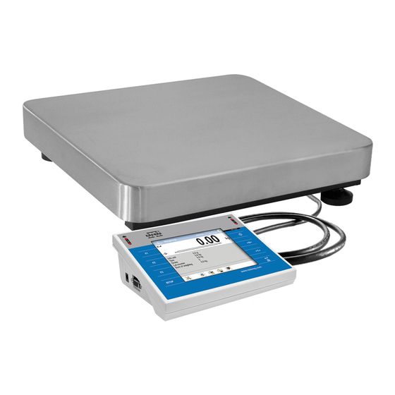
1. INTENDED USE WPY scales are the response for the market demands concerning simplicity of operation and high functionality. They are intended for quick and precise weighing in industrial and laboratory conditions. The state-of-the-art weighing terminal with TFT 5.7” colour graphic displays with touch panels allows for intuitive operation without using keys. -
Page 8: Unpacking And Mounting
G. Contact with the central authorized service: +48 48 384 88 00 ext. 106 or 107. 4. UNPACKING AND MOUNTING 4.1. Scales of WPY/C series A. Take the device out of the package, B. Put the scale on an even stiff ground, C. -
Page 9: Scales Of Wpy/D Series
4.2. Scales of WPY/D series A. Take the device out of the package, B. Put the scale on an even stiff ground, C. Fit the pan and the bracket under the device according to the drawing: E. Scale should be levelled by turning regulation feet. Levelling is correct if air bubble is situated in the central position: 5. - Page 10 WPY/C1/R series – main dimensions WPY/C1/K series – main dimensions...
-
Page 11: Scales Of Wpy/D Series
WPY/C2/R series – main dimensions WPY/C2/K series – main dimensions 5.1.2. Scales of WPY/D series... -
Page 12: Description Of Connectors
5.2. Description of connectors 5.2.1. Connectors’ description in PUE 7 1 – Ethernet RJ45 1 – power supply socket 2 – RS232 (COM1) 2 – I/O, RS232 (COM2) 3 – USB 5.2.2. Connectors’ description in PUE 7P 1 – Ethernet RJ45 1 –... -
Page 13: Connector With Rs232 And I/O
• Press to start the operating system loading procedure. Windows CE together with RADWAG software loading is signalled by blinking the red diode ON/LOAD. • When the loading procedure is completed the main software window appears. -
Page 14: Keypad Overlay
7. KEYPAD OVERLAY 8. FUNCTIONS OF KEYS Description Turning on/off the scale Zeroing Tarring Printing out the result or confirming some entered data Function key (entering the menu) Programmable key Programmable key Programmable key... -
Page 15: Program Structure
9. PROGRAM STRUCTURE The main menu has been divided into twelve functional groups. In every group there are parameters of similar use. 9.1. Main menu items Pictogram Description Scale Databases Working Modes Communication Devices Display Inputs / Outputs Authorization Units Other User Calibration Info... -
Page 16: Inventory Of Parameters
9.2. Inventory of parameters 9.2.1. Scale parameters - weighing Pictogram Description Value Median Filter Filter Fast Autozero LO threshold Last digit Always 9.2.2. Working modes Pictogram Description Value Accessibility Weighing Parts counting Percent setup Dosing Recipes Animal weighing Density Weighing Manual, each Save Mode stable... - Page 17 Tare mode Single Labelling mode Number of labels No. of cumulative labels No. of CC labels C label automatic triggering Mode None Threshold CC label automatic triggering Mode None Threshold Statistics Global Parts counting Automatic correction of reference mass Minimum reference mass Manual, each Save Mode stable...
- Page 18 No. of CC labels C label automatic triggering Mode None Threshold CC label automatic triggering Mode None Threshold Statistics Global Percent setup Manual, each Save Mode stable Down-weighing Checkweighing Tare mode Single Labelling mode Number of labels No. of cumulative labels No.
- Page 19 Threshold Statistics Global Dosing Ask for multiplier Ask for number of cycles Confirm batching ingredients manually No. of weighings for calculating the correction Global Batching outputs Output 1 Output 2 Output 3 Output 4 Bulk batching output Output 1 Output 2 Output 3 Output 4 Correction...
- Page 20 Automatic tare Ingredient control Portion weighing Animal weighing Averaging time Automatic mode Checkweighing Tare mode Single Labelling mode Number of labels No. of cumulative labels No. of CC labels C label automatic triggering Mode None Threshold CC label automatic triggering Mode None Threshold...
-
Page 21: Communication
Sinker volume Ask abort sample number Pycnometer mass Pycnometer density Unit g/cm Manual, each Save Mode stable Checkweighing Tare mode Single Statistics Global 9.2.3. Communication Pictogram Description Value COM1 Baud Rate 9600 Data bits Stop bits Parity None COM2 Baud Rate 9600 Data bits Stop bits... -
Page 22: Devices
Ethernet DHCP IP Address 192.168.0.2 Subnet mask 255.255.255.0 Gateway 192.168.0.1 192.168.0.1 MAC Address Port 4001 9.2.4. Devices Pictogram Description Value Computer Port None Address Continuous transmission Weighing Printout Template E2R System System is active Lock selecting products Printer... - Page 23 Port RS 232 (1) Code page 1250 Printouts Weighing printout template See ch. 16.2.3 Cumulative printout template See ch. 16.2.3 Cumulative printout template See ch. 16.2.3 for cumulative data Adjustment report printout template See ch. 22.3 Dosing report printout template See ch.
-
Page 24: Display
Test See ch. 16.3.4 Transponder card reader Port None Additional display Port None Template See ch. 16.5.2 9.2.5. Display Pictogram Description Value Text information Displaying template See ch. 17.1.1 Left displaying template See ch. 17.1.1 Right displaying template See ch. 17.1.1 Font Type Courier... - Page 25 Button functions See ch. 17.2 Show all platforms Bargraph Bargraph type None Fast weighing MIN, MAX thresholds working mode Unstable OK threshold working mode Unstable Min threshold signalling colour OK threshold signalling colour Intense green Max threshold signalling colour Gradient Background colour Black Frame colour...
-
Page 26: Inputs / Outputs
Frame colour White Linear Min threshold signalling colour OK threshold signalling colour Green Max threshold signalling colour Min Max range background colour Turquoise OK range signalling colour Turquoise Gradient 9.2.6. Inputs / Outputs Pictogram Description Value Inputs Input 1 None Input 2 None Input 3... -
Page 27: Authorization
9.2.7. Authorization Pictogram Description Value Anonymous operator Operator Date & Time Administrator Printouts Administrator Databases Products Administrator Clients Administrator Dosing processes Administrator Recipes Administrator Packages Administrator Warehouses Administrator Labels Administrator Weighing counter Administrator Delete older data Advanced Operator 9.2.8. Units Pictogram Description Value... -
Page 28: Other
Start unit None Defined unit 1 Multiplier Name Defined unit 1 Multiplier Name Acceleration of gravity 9.80665 9.2.9. Other Pictogram Description Value Language Polish Date & Time Beep Touch screen calibration Screen brightness Cursor... -
Page 29: User Calibration
9.2.10. User Calibration An option only for non-verified scale Pictogram Description Value Setting of start mass Calibration Report printout Adjustment track record 9.2.11. Info Submenu < Info> is for viewing information: • Scale factory number, • Program version, • Scale program version. 9.2.12. -
Page 30: Indicating Window
10. INDICATING WINDOW Main view: In the main application window one can see four separate parts: • Upper bar, • Weighing window, • Workspace, • Function keys. 10.1. Upper bar The upper bar on the display contains the following data: Pictogram and name of an active working mode Logged user Pictogram of an active connection with a computer... -
Page 31: Weighing Window
10.2. Weighing window The weighing window contains data on carried out weighing process: 10.3. Workspace The workspace is located under the weighing window: The workspace features three displaying templates. The upper section of the workspace comprises a graphic information on which of the three templates is enabled. -
Page 32: Logging In
11. LOGGING IN In order to have full access to user parameters and databases, the user should log in as an <Administrator>. 11.1. Logging in procedure • While in the main window press <log in> text located in the upper bar of the display and the window with operators attributed to <... - Page 33 Access to user parameters, databases and working modes depending on the authorization access level attributed: Operator type Access level description No access to user parameters. No weighing can be confirmed. None Cannot enter the reference mass unit and estimate the reference mase unit by weiging in „Counting Pieces”...
-
Page 34: Navigating Within The Menu
2. A user logged in as <Administrator> in submenu Authorizations> (see ch. 19 of this manual) can change < authorization levels for accessing different databases and functions: Weighing counter>. The exception < Delete older data>, < are database < Weighings / Alibi>, that have the status „Read only”. -
Page 35: Return To Weighing
Searching a database according to a code Printing on item from a database Clearing an editing field Screen keyboard on / off Reading a printout template from a *.lb file (active after connecting a pendrive) Variables for a printout template One level up Immediate exit to the main window 12.2. -
Page 36: Conditions Of Operational Use
13.1. Conditions of operational use In order to assure a long term operating period with appropriate measurements following principles should be adhered to: • Avoid applying mechanical shocks to the weight pan: • Loads should be placed in the centre of the pan (eccentric errors are outlined in PN-EN 45501 chapter 3.5 and 3.6.2): •... -
Page 37: Zeroing
13.2. Zeroing In order to zero the indication choose a platform on the touch panel and press . After zeroing is performed the indication is equal zero and following symbols usually appear: Zeroing is possible only when the indication is stable. Notice: Zeroing is possible only within ±2% of full range around zero. -
Page 38: Weighing For Dual Range Scales
• The program returns to weighing and the and the display shows the entered value with the „–” sign provided there was zero before on the display. 13.5. Weighing for dual range scales Switching between the I range and the II range happens automatically (exceeding Max of the I range). -
Page 39: Scale Parameters
– weighing unit inaccessible in a verified scale Notice: 1. The user can also declare the start unit and determine two custom weighing units (user defined) – see point 20 of this user manual; 2. The procedure of attributing functions to buttons is described in ch. 17.2 of this manual. -
Page 40: Median Filter
14.1. Median filter The median filter is intended for eliminating short-lasting mechanical shocks. Procedure: • Enter < Weighing> according to ch. 14 of the manual, select Median Filter> and then set an appropriate value. < Accessible settings: None - median filter is off 0.5, 1, 1.5, 2, 2.5 - filtering level to choose 14.2. -
Page 41: Minimum Weight For Different Functions (Lo)
If AUTOZERO is disabled zero is not corrected automatically. However, in particular cases, this function can disrupt the measurement process e.g. slow pouring of liquid or powder on the weighing pan. In this case, it is advisable to disable the autozero function. Procedure: •... -
Page 42: Communication
Accessible settings: Last digit always visible Always Last digit always switched off Never Last digit visible only on stable indication of mass When stable 15. COMMUNICATION The scale can communicate with external devices via different ports: • RS232 (1), • RS232 (2), •... -
Page 43: Ethernet Setting
15.2. ETHERNET setting Procedure: • Enter < Communication> according to ch.15 of the manual, select < Ethernet> and then set an appropriate value. Following settings are accessible for Ethernet: • DHCP - Yes – No • IP Address - 192.168.0.2 •... -
Page 44: Devices
Tcp / with the screen keyboard, • Enter the required number and press Notice: The number of TCP port in RADWAG instruments is set to default value: 4001. 16. DEVICES 16.1. Computer The scale can cooperate with a computer. Active connection scale-computer is signalled by icon in the top bar of the main window. -
Page 45: Computer Address
16.1.2. Computer address Procedure: • Enter < Devices> parameter group as described in chapter 16 of the manual, • Choose „ Computer / Address” then the window <Address> with the screen keyboard appears, • Enter the required address and confirm it by pressing 16.1.3. -
Page 46: Cooperation With „E2R System
Procedure: • Enter < Devices> parameter group as described in chapter 16 of the manual, • Choose „ Computer / Weighing Printout Template” then the editing field <Weighing Printout Template> with the screen keyboard appears, • Modify the template if necessary and confirm the changes by pressing Notice: There are additional buttons in the bottom line of the screen keyboard. -
Page 47: Printer
• Choose „ Computer / E2R System / System is active” and then set an appropriate value. Accessible settings: System is not active System is active • If during cooperation with < E2R System> product selection lock is required for operators, go to parameter < Lock selecting products>... -
Page 48: Printer Code Page
16.2.2. Printer code page Procedure: • Enter parameters < Devices> as described in chapter 16 of the manual, • Choose „ Code Page” then the screen keyboard Printer / will be displayed, • Write the required code page and confirm by pressing Notice: The default value is 1250 –... -
Page 49: Barcode Scanner
Default printouts’ settings: Weighing Printout Template Cumulative Printout Template N={15} SUM={16} Cumulative of Cumulative Printout Template N2={20} SUM2={21} Product Printout Template {50} {51} Operator Printout Template {75} {76} Client Printout Template {85} {86} Warehouse Printout Template {130} {131} Package Printout Template {80} {81} {82}... -
Page 50: Port For Barcode Scanner
Notice: A special protocol is required in order the code be received by RADWAG equipment. It is required to program an appropriate prefix and suffix. Prefix – one byte 01 hexadecimally, suffix one byte 0D hexadecimally. -
Page 51: Field Selection
• Chose parameter < Suffix> and then enter, using the screen keyboard, a required value (hexadecimal) and confirm it by pressing 16.3.3. Field selection This option is connected with selecting data which the program will search after reading a barcode. Procedure: •... - Page 52 Setting the number of characters to be taken for Code length the search procedure counting form Offset Start marker declaration Start marker End marker declaration End marker Notice: An exception from the above is < Recipe>, which features an additional submenu <...
-
Page 53: Test
16.3.4. Test Operators, using parameter < Test>, can verify if a barcode connected to the scale works properly. Procedure: • Enter submenu < Barcode Scanner> according to ch. 16.3 of this manual, • After entering parameter < Test> window <Test> is opened with an ASCII text box and HEX (hexadecimal) field, •... -
Page 54: Com Port For Transponder Card Readers
16.4.1. Com port for transponder card readers Procedure: • Enter group of parameters < Devices> according to ch. 16 of this manula, select „ Transponder cards reader / Port” and set appropriate option. The scale can communicate with the reader via following ports: •... -
Page 55: Additional Display
16.5. Additional display 16.5.1. Additional display port Procedure: • Enter parameters group < Devices> according to ch. 16 of this manual, select „ Additional display / Port” and then choose an appropriate option from the list. Communication with additional displays can be performed via following ports: •... -
Page 56: Display
• Confirm the changes by pressing Notice: In default settings parameter < Sample> has ascribed {141} (display WD series). 17. DISPLAY Users can adapt the main display and visible information to their needs. All parameters of the display can be found in the parameters’ group Display>. -
Page 57: Display Templates
Declaring font size of text data displayed Font size in the workspace. Available font size: Small, Medium, Large. Bolded font for text data displayed in the Bold font worspace. Tilt Text data in the workspace in italics. Font colour for text data in the Colour workspace. - Page 58 • Edit the content of the selected displaying template and accept it by pressing key. Notice: There are additional buttons in the bottom line of the screen keyboard. They can be used while modifying a display template. : Screen keyboard on/off Reading a display template from a *.lb file (button active while connecting a USB pendrive).
-
Page 59: Function Keys
17.2. Function keys In submenu < Actions> users can set actions following keys: function keys, screen keys, proximity sensors. Function keys and proximity sensors are programmable specifically for each working mode. If a button has been attributed then it is equal to activating a function. - Page 60 F2 Button - Choose client F3 Button - Set tare Screen button 1 - Local parameters Screen button 2 - Choose package Screen button 3 - Insert unit mass Screen button 4 - Estimate unit mass Screen button 5 - Ascribe standard F1 Button - Choose product Percent setup:...
- Page 61 F2 Button - Choose client F3 Button - Set tare Screen button 1 - Local parameters Screen button 2 - Select recipe Screen button 3 - Start Screen button 4 - Stop Screen button 5 - Emergency stop Screen button 6 - Previous component Screen button 7 - Next component...
-
Page 62: Displaying Platforms
Notice: The list of functions that can be attributed to keys or buttons is listed in APPENDIX B of this manual. 17.3. Displaying platforms If a scale is equipped with two platforms users can switch between platforms in three ways: •... -
Page 63: Bargraph "Quick Weighing
Procedure: • Enter submenu “ Bargraph” in accordance with Display / point 17 of this user manual, • Seelct option < Bargraph type> and set desired bargraph type. Accessible bargraphs: • Quick weighing, • None (Bargraph is not displayed), • Signalling checkweighing ranges, •... -
Page 64: Bargraph "Signalling Of Checkweighing Ranges
Means of operation: • The bargraph consists of 8 red fields and three green fields. • The green fields signal weighings between MIN and MAX threshold, where: MIN = the minimum threshold of acceptable weighing - LO MAX = the maximum threshold of acceptable weighing - HI •... -
Page 65: Bargraph Type: „Linear
Stable – signalling of OK thresholds is previewed on exceeding LO threshold and OK threshold working mode reaching stable measurment result; Unstable – signalling of OK thresholds is previewed on exceeding LO threshold Colour selection for signaling MIN threshold. Min threshold signalling colour 18 colours palette available. - Page 66 Colour selection for signaling MIN Min threshold signalling colour threshold. 18 colours palette available. Colour selection for signaling OK OK threshold signalling colour threshold. 18 colours palette available. Colour selection for signaling MAX Max threshold signalling colour threshold. 18 colours palette available. Background colour selection for MIN, Min Max range background colour MAX range of the bargraph.
-
Page 67: Inputs / Outputs
18. INPUTS / OUTPUTS Scale are equipped with 4 inputs / 4 outputs. To adjust software to the users needs configure inputs outputs in the submenu in the submenu < Inputs / Outputs>: • indicator inputs, • indicator outputs. In order to enter submenu < Inputs / Outputs>, press and then „... -
Page 68: Authorization
Output disabled None Stable weighing result over LO threshold value Stabile Stable weighing result below the MIN threshold MIN stable Non-stable weighing result below the MIN threshold MIN non-stable Stable weighing result between MIN and MAX OK stable thresholds Non-stable weighing result between MIN and MAX OK non-stable thresholds Stable weighing result over the MAX threshold... -
Page 69: Date And Time
Procedure: • Enter < Authorization> according to ch. 19 of this manual, choose < Anonymous Operator>, and then set the authorization access level. Accessible authorization levels: None, Operator, Advanced Operator, Administrator. 19.2. Date and time Default settings allow a logged-in Administrator to change settings of date and time. -
Page 70: Databases
Procedure: • Enter parameter group < Authorization> according to ch. 19 of this manual, choose < Printouts>, and set appropreately. Access levels to printouts that can be set: None, Operator, Advances Operator, Administrator. Notice: When you choose setting <None> printout templates can be changed even without logging on. -
Page 71: Delete Older Data
19.5. Delete older data Default settings allow a logged-in Advanced Operator to delete older data from the < Weighings / Alibi> database. Software however allows to change the access level to this option: < Delete older data>. Procedure: • Enter parameters’ group < Authorization>... -
Page 72: User Defined Units
Possible selection: • none • gram [g] • kilogram [kg] • carat [ct] • pound [lb] • ounce [oz] * • Newton [N] * – weighing unit inaccessible in a verified scale • Exit to main manu with procedure of saving changes, •... -
Page 73: Acceleration Of Gravity
20.3. Acceleration of gravity Parameter < Acceleration of gravity> eliminates the changes of gravitational acceleration force at different latitudes and altitudes in case of weighing process with application of “Newton” [N] weighing unit. Procedure: • Enter submenu < Units> in accordance with ch. 20 of this user manual, •... -
Page 74: Setting Date And Time
21.2. Setting date and time Users can set date and time that are visible in the main window of the display. Entering the edition of date and time can be made in two ways: • Pressing the field „date and time” in the top bar of the main screen, and then •... -
Page 75: Screen Brightness
• Using a thin and soft pointer press (keep pressed for some time) in the point where the cross appears, after indicating the 4 place confirm changes by pressing ENTER/PRINT. 21.5. Screen brightness Scale user can change brightness of the screen in the range between 0% and 100%. -
Page 76: User Adjustment
22. USER ADJUSTMENT An option only for non-verified scale Scales require to recalculate internal divisions to more suitable ones (e.g. g, kg etc.). In order to do this they require an adjustment factor. It is adjusted during the adjustment procedure using a mass standard. Adjustment should be carried out if weighing a standard mass shows a different mass value. -
Page 77: Start Mass Adjustment
• Place determined mass on pan of platform 1 and then select • After the procedure of adjustment factor determination following command appears: • Accept the message box by pressing key and return to weighing mode. < Setting of start mass> parameter allows to adjust start mass of platform 1. -
Page 78: Report From Adjustment Process
• Take the load off the pan of platform 1, • Press button . The following message appears during adjusting start mass: „Evaluation of starting mass”, • After the procedure has been completed the following message box appears: • Accept the message box by pressing key and return to weighing mode. -
Page 79: Adjustment Track Record
22.4. Adjustment track record Each completed adjustment process is automatically saved in scale’s database in submenu < Adjustment track record>. In order to enter submenu < Adjustment track record >, press key, and Adjustment track record”. Files „ User Adjustment / comprising reports have names with time and date when the process was performed. - Page 80 • Select parameter < Software version on server> which reads software version and its availability date on RADWAG server. Notice: In case of no connection with the global network Intranet or incorrect settings of Ethernet parameters, the scale displays the following No connection”.
-
Page 81: Update From Pendrive
• Accept the message by pressing key. The terminal shall restart with update installing procedure. 23.2. Update from pendrive Procedure: • Copy file “update.pue7” containing the current software version onto the external data storage device (to the main catalogue), • Connect the data storage device to terminal’s USB port, •... -
Page 82: Changes In Software
• Accept the message by pressing key. The terminal shall restart with update installing procedure. 23.3. Changes in software Parameter < Changes in software> enables acquiring data on changes present in the updated software version. Procedure: On completing the software updating procedure go to parameter Changes in software>... - Page 83 Recipes Weighing animals Density Work modes can be configured in < Working Modes>. To enter submenu < Working Modes>, press and then „ Working Modes”. The settings of specific working modes provide access to special functions adjusting operation of the instruments to client’s individual needs. Notice: 1.
-
Page 84: Working Modes Accessibility
24.1. Working modes accessibility Submenu < Accessibility> enables declaring presence of scale’s working modes in the user menu after pressing a pictogram with a working mode located in the left corner of the upper bar in the main window. Procedure: •... -
Page 85: Down-Weighing
24.3. Down-weighing Software allows to weigh in the “down-weighing” mode. It consist in putting the load on the pan and taking off/removing portions of it with concurrent saving weighings equal to the portions taken off the pan. Procedure: • Enter parameters group < Working Modes>... -
Page 86: Labelling Mode
Procedure: • Enter parameters group < Working Modes> according to ch. 24 of this manual, • Enter the required working mode and choose < Tare mode> and then set the required option. Options: Basic tare mode. The set (chooden) tare value is Single overwritten after entering a new value Summing up tare values of product and package together... -
Page 87: Setting Of The Number Of Labels To Print
24.6.1. Setting of the number of labels to print In the parameter < Number of labels> user defines the amount of labels. They are printed on the printer connected to the weight. Procedure: • Enter parameters group < Working Modes> according to ch. -
Page 88: Automatic Triggering Of Cumulative Labels
Procedure: • Enter parameters group < Working Modes> according to ch. 24 of this manual, • Enter the required working mode and choose: „ Labelling mode / No. of CC labels”, then the editing field <No. of CC labels> with the screen keyboard is opened, •... -
Page 89: Automatic Triggering Cumulative Labels Of Cumulative Labels
Printing followed by zeroing label counter or the total mass Printing without zeroing label counter or the total mass By default setting button is accessible in the bottom part of the display but activating the button can be done in submenu: „... - Page 90 • Enter the required working mode and choose: „ Labelling mode / Mode” and then set the CC label automatic triggering / required option: Cumulative label of cumulative labels printout is initiated None by pressing Cumulative label of cumulative labels printout is initiated by Mass exceeding the value set in parameter <...
-
Page 91: Statistics
− If parameter < Mode> is set to <Number> use the screen keyboard to enter the required counter value as a threshold to trigger off printing CC labels. • Confirm the changes introduced by pressing 24.7. Statistics All statistics are continuously updated after each measurement is saved in the scale memory. -
Page 92: Starting The Working Mode
25.1. Starting the working mode The < Weighing> mode is the standard working mode. If a user has changed the operating mode to another follow the actions below: • While in the main window press the icon with mode name placed on the top bar on the left then submenu comprising all accessible working modes <Working Modes>... -
Page 93: Starting The Working Mode
26.1. Starting the working mode Procedure: • While in the main window press in the top bar, then you will see a submenu <Working Modes> comprising a list of modes, • Choose < Counting Pieces>, program automatically returns to the main window displaying icon in the top bar, •... -
Page 94: Automatic Correction Of Reference Mass
26.2.1. Automatic correction of reference mass It concerns the < Counting pieces> working mode Working mode < Parts counting> comprises a special function Automatic correction of reference mass>, that can be used for < correcting the unit mass <SMP>. To enable the function in parameters you need to: •... -
Page 95: Minimum Reference Mass
26.2.2. Minimum reference mass It concerns the < Counting pieces> working mode Users before beginning the procedure of single piese mass evaluation can declare “minimum reference mass” i.e. minimum total weight of all pieces put on the scale pan expressed in reading divisions. Procedure: •... -
Page 96: Setting A Reference Unit By Weighing A Sample
26.4. Setting a reference unit by weighing a sample Procedure: • Enter mode < Parts counting> according to ch. 26.1 of this manual, • If pieces are weighed in a container it needs to be put on the pan and tarred, •... -
Page 97: Inscribing The Unit Mass To The Database
Procedure: • While in < Parts counting > press • Using choose a product and confirm it by pressing Notice: The selected product has to have declared unit mass (single piece mass). 26.6. Inscribing the unit mass to the database The unit mass can be described a unit mass the following way: a) Estimate the unit mass (see 26.2 and 26.3), b) Enter the products database... -
Page 98: Local Settings Of The Workign Mode
• Choose mode < Deviations>, the program will automatically returns to the main window displaying icon in the top bar • The weight unit is automatically changed to „%” and two screen buttons on the right side appear: Enter reference mass Estimate reference mass 27.2. -
Page 99: Rederence Unit Mass Inscribing Into The Memory
• Put the load on the pan. After stabilization the result is taken as a standard (symbol ). Confirm it by pressing • At the same time the weight unit is changed to (w %). 27.4. Rederence unit mass inscribing into the memory Procedure: •... -
Page 100: Dosing Process Structure
• Automatically the following on-screen key are enabled: Local parameters Select dosing process Start dosing process Stop dosing process Emergency stop 28.2. Dosing process structure All activities related to the dosing process can be carried out from the level of scale. Each dosing process < >... -
Page 101: Local Setting Of A Working Mode
28.3. Local setting of a working mode Local settings for the working mode < Dosing> are accessible on pressing a hot key < Local parameters>: Causes setting a question for dosing process multiplier, i.e. the number which is Ask for multiplier used to multiply the values of mass of all components. - Page 102 Mass Mass of an ingredient to be dosed MIN threshold for dosing process ingredient MAX threshold for dosing process ingredient Dosing process ingredient uploaded from Product Products database Enables switching on checkweiging mode Down-weighing (weighing on minus) Function enabling automatic weighing (automatic dosing).
- Page 103 Weight condition function determining time in which the following step of dosing process ona weighing platform should be carried out, e.g.: Weight condition [CM] the following step is carried out if mass (net or gross) placed on the weighing platform is below the value set in threshold.
-
Page 104: Creating A New Dosing Process
28.5. Creating a new dosing process Creating a new dosing process is initiated by specifying its name and code, followed by determining processes on each of the weighing platforms. Procedure: • Press key and select option < Databases> from main menu ... -
Page 105: Instances Of Dosing Processes
28.6. Instances of dosing processes 28.6.1. Instance 1 – Manual dosing process of 4 ingredients on 2 weighing platforms Description: A dosing process contains 4 ingredients, which are weighed on two weighing platforms: • Weighing Platform 1: ingredients: Flour and Sugar •... - Page 106 [5s] Place Pending for loading an empty container 8. [TI] Delay empty for the second product container Input 1 has to take increasing tendency – 9. [CI] Input condition Input 1 – „/” press function key confirming loading a container 10.
-
Page 107: Instance 2 - Automatic Dosing Of 2 Ingredients On 2 Weighing Platforms
8. [CF] Flags Signal flag 1 – Checking condition, whether signal flag 1 condition „1” is set to value “1” – i.e. checking whether desired part of the process has been already realized on the weighing platform no. 1. If Yes, then dosing process on the second weighing platform shall continue. - Page 108 The dosing process is carried out automatically, and includes a condition, that the dosing sequence is strictly determined – dosing of “Water” ingredient can be initiated only on completing the dosing process of ingredient “Flour”. The condition is marked with signal flags, which determine recipe making process between the weighing platforms, in a way which orders dosing Water ingredient as the second one.
-
Page 109: Instance 3 - Mixed Dosing Process
Platform 2 Icon Step Value Description 1. [CF] Flags Signal flag 1 – Checking condition, whether signal flag 1 condition „1” is set to value “1” – i.e. checking whether desired part of the process has been already realized on the weighing platform no. - Page 110 The condition is marked with signal flags, which determine recipe making process between the weighing platforms, in a way which orders dosing “Water” ingredient is dosed in an appropriate time. The whole process is described below in tables, separately for each weighing platform. Dosing process name: Instance 3 Dosing process code: 3333 Dosing process from a termial level:...
- Page 111 16. [Z] Zero Zero Zeroing the weighing platform no. 1 17. [CI] Input Input 5 – „1” Confirm pouring ingredients to a mixer condition 18. [F] Set Signal flag 1 – „1” Setting the characteristic point of the flags process, which is a condition for carrying out part of the process on the weighing platform no.
-
Page 112: Reporting Of Completed Dosing Processes
7. [O] Output 12 – „1” Output 12 akes high status (“1”) – signal confirming Outputs carrying out the dosing process on the weighing platform no. 2 is lit up 8. [F] Set Signal flag 1 – „1” Setting the characteristic point of the process, which flags Signal flag 2 –... -
Page 113: Working Modes - Recipes
29. WORKING MODES – RECIPES Recipes> is a working mode designed for creating recipes of products < on a scale. 29.1. Starting the working mode Procedure: • While in main window of the software, press on-screen key, located in the upper bar of the window, which opens submenu < Working Modes>... -
Page 114: Local Setting Of A Working Mode
29.2. Local setting of a working mode Local settings for the working mode < Recipes> are accessible on pressing a hot key < Local parameters>: Causes setting a question for recipes multiplier, i.e. the number which is used to multiply the Ask for multiplier values of mass of all recipes components. - Page 115 Defining recipe ingredients Ingredients Previewing number of ingredients in a recipe Number of ingredients Previewing total mass of a recipe Recipe mass Type of a measuring series for a recipe Type of charge * A measuring series of a recipe Charge *) –...
- Page 116 Enabling down-weighing (weighing to minus)mode Dispensing 1) – In case of selectng an ingredient from the database of products the software displays the following message: 2) – in case of declaring mass of an ingredient, and when the mass exceeds the maximum capacity of a weighing platform, the software displays the followinf message: 3) –...
-
Page 117: Recipe Making Process
• On entering the required data press key which is equal to creating a new ingredient and adding it to the recipe composition. • A created entry on the list comprises: the folowing number on the list, ingredient’s name (selected from the database of products) and mass to be weighed. - Page 118 • Press an on-screen button to select a required recipe. • Enter to scale’s memory gerenal parameters on the working mode (in accordance with point 29.2of this user manual), • After returning to the main window of the < Recipes> mode press the on-screen function key (process start), •...
- Page 119 Process in progress: Test recipe Ingredient: 1 / 3 [ Ingredient 1 ] Portion: 0 g / -500.0 g Charge: 1 / 10 Completed: 0% Where: Process status Process in progress: Name of prepared recipe Test recipe Number of weighed ingredient / Total number of Ingredient: 1 / 3 ingredients in a recipe...
-
Page 120: Reporting From Completed Recipe Making Processes
A user can abort the recipe making process at optional moment by pressing an on-screen function key (process stop) located i nthe bottom bar of the terminal’s display. 29.5. Reporting from completed recipe making processes On completing each recipe making process, the terminal automatically generates a report on that process. -
Page 121: Working Modes - Density
30. WORKING MODES – DENSITY Working mode < Density> enables determining density of solids, liquids and materials of high viscosity. The density is determined on basis of Archimedes principle, according to which any floating object displaces its own weight of fluid. The density mode also enables utilizing a pycnometer for determining density of liquids. -
Page 122: Carrying Out Density Determination Procedure
Ask about sample Function ordering inserting number of a sample before initaining the test procedure number Parameter designed for manual determining mass of a pycnometer expressed in [g]. If inserted value is equal Pycnometer mass to „0” then on test procedure start, the pycnometer mass shall be measured. - Page 123 Process course: • Press < Local parameters> key to enter the setting of local parameters in density mode. • Press < Sinker volume> in order to insert the volume of the sinker (given in [cm ]) which is immersed in the tested liquid. •...
-
Page 124: Determining Density Of Solids
30.3.2. Determining density of solids Density of solids is determined by weighing a solid object in two different medium: in the air and in auxiliary liquid with determined density. The difference between the two measurements is displacement weight, which is used by scale software to calculate the density of tested solid. Before starting the measurement select <... -
Page 125: Determining Density Of Pycnometer
Caution: If in the local parameters, < Ask about sample number> function is enabled, then on initiating the process, the system asks for inserting the number of tested sample. The inserted sample number is linked to the process data and saved in the database. •... - Page 126 The excess of liquid pouring through the capillary tube is removed with an absorbent paper. Then, the vessel is immediately placed on a scale, and its mass is determined as quickly as possible. During the mass measurement, due to contraction of the volume of liquid its level usually noticeably decreases in the capillary tube, but this does not matter if at the time of placing instrument on the scale, it was completely filled and had correct temperature.
-
Page 127: Determining Density Of A Porous Body
Caution: If in the local parameters, < Ask about sample number> function is enabled, then on initiating the process, the system asks for inserting the number of tested sample. The inserted sample number is linked to the process data and saved in the database. •... - Page 128 Process course: • Press < Local parameters> key to enter the setting of local parameters in density mode. • Press < Standard liquid> key to select the auxiliary liquid used for the density determination procedure. If the auxiliary liquid is other than “Water”...
-
Page 129: Reporting From Completed Density Determination Processes
• On carrying out the third measurement, the scale automatically determines the density of the porous body, and indicates the result on terminal’s display. If the user needs a report from the density determination process, it can be printed on a plugged printer by pressing key. -
Page 130: Table Of Density Parameter For Water
30.5. Table of density parameter for water T/°C 0.99973 0.99972 0.99971 0.99970 0.99969 0.99968 0.99967 0.99966 0.99965 0.99964 0.99963 0.99962 0.99961 0.99960 0.99959 0.99958 0.99957 0.99956 0.99955 0.99954 0.99953 0.99951 0.99950 0.99949 0.99948 0.99947 0.99946 0.99944 0.99943 0.99942 0.99941 0.99939 0.99938 0.99937 0.99935 0.99934 0.99933 0.99931 0.99930 0.99929 0.99927 0.99926 0.99924 0.99923 0.99922 0.99920 0.99919 0.99917 0.99916 0.99914 0.99913 0.99911 0.99910 0.99908 0.99907 0.99905 0.99904 0.99902 0.99900 0.99899 0.99897 0.99896 0.99894 0.99892 0.99891 0.99889 0.99887 0.99885 0.99884 0.99882... -
Page 131: Working Modes - Animal Weighing
31. WORKING MODES – ANIMAL WEIGHING Working mode < Animal weighing> enables weighing objects which do not stabilize if placed on scale’s weighing platform and while carrying out weighing process. Weighing process is achieved by implementing parameter of time for stability of measurement, which is set in global parameters of the working mode. -
Page 132: Carrying Out Animals Weighing Procedure
Declaration of process duration in seconds (from 1s to 90s) – measurements carried out in set time Averaging time interval are used to calculate mean value, which is the result of the measurement Operation mode, in which the scale automatically begins the following measuring process, if the load Automatic mode placed on scale’s weighing platform exceeds value... -
Page 133: Searching Databases
Clients Dosing processes Reports From dosing Recipes Reports from recipes Density Packages Warehouses Labels Universal variables Weighing counter In order to enter < Databases>, press and choose < Databases>. 32.1. Searching databases Users can quickly search databases according to the following criteria: •... -
Page 134: Quick Name Search
32.1.1. Quick name search Procedure: • Enter < Databases> according to ch. 32 of the manual, • Enter < Products>, • Press , then an editing field appears <Search by name> with the screen keyboard, • Inscribe the name of a product or its part and press •... -
Page 135: Adding New Items In Databases
32.2. Adding new items in databases Procedure: • Enter < Databases> according to ch. 32 of this manual, • Enter database < Products>, • Press , then the message is displayed: <Create new record?>, • Confirm it by pressing , the program automatically enters edition of new record. -
Page 136: Printing Items From Databases
Caution: Factory settings prevent users from deleting weighings that are up to one year old. Because of incompatible regulations in different countries concerning the time of protecting data this period can be modified by distributors. Procedure: • Enter the submenu < Databases>... -
Page 137: Export A Database To A File
Notice: Default printout templates for printing records from different databases are described in ch. 16.2.3 of this manual. 32.6. Export a database to a file An operator after a series of weighings can export a database to a file using a pendrive. Additionally, a user can select data to be exported. Procedure: •... - Page 138 Checkweighing Platform number Statistics: Number of measurements Weighing counter Automatic selection of data to be exported (unfilled fields are omitted) *) – • After declaring data to be exported go back to the submenu Export database of weighings to a file> and select option <...
-
Page 139: Database Edition
32.7. Database edition The database edition can be performed by an administrator. 32.7.1. Operators’ database Procedure: • Enter < Databases> according to ch. 32 of this manual, • Enter < Operators> and press the required position. Record of operator: Operator name Name Operator code Code... - Page 140 Product record: Product name Name Product code Code Product barcode EAN code Nominal product mass Mass Declaring numbers of outputs for fine dosing Batching outputs Declaring numbers of outputs for bulk dosing Bulk batching output Value of dosing correction for weighing Correction 1 platform no.
-
Page 141: Database Of Weighings / Alibi
Constant product date Date Value Added Tax in [%] Dialogue box for entering ingredients Ingredients Basic label template attributed to a product Label Cumulative label template attributed to a C Label product Cumulative of cumulative label template CC Label attributed to a product 1) –... -
Page 142: Database Of Clients
Product name Product Operator name Operator Client name Client Number of produced lot Lot number Number of produced batch Batch number Source warehouse name Source warehouse Target warehouse name Target warehouse Package name Package A weighing threshold (MIN, OK or MAX) Checkweighing Platform number to perform weighings Platform number... -
Page 143: Databse Of Dosing Processes
Client’s address Address Client’s postal code Postal code Client’s Town/City City Client’s discount Discount Client’s label template Label 32.7.5. Databse of dosing processes Procedure: • Enter < Databases> according to ch. 32 of this manual, • Enter < Dosing processes> and press the required position. List of data for a selected dosing process: Dosing process name Name... -
Page 144: Database Of Recipes
• Enter < Reports from dosing> and press the required position. List of data for a selected report from dosing: Status of correctness for a completed dosing process Status Start date of dosing process Start date End date of dosing process End date Name of completed dosing process Dosing process... -
Page 145: Database Of Reports From Recipes
Type of measuring charge of a recipe Type of charge Measuring chanrge of a recipe Charge 32.7.8. Database of reports from recipes Procedure: • Enter < Databases> according to ch. 32 of this manual, • Enter < Report from recipes> and press the required position. List of data for a specific report from a recipes: Status of correctness for a completed recipe Status... - Page 146 List of data for a specific report from density determination process: Number of sample for which the density is Sample number determined Start date of density determination process Start date End date of density determination process End date Value of determined density Density Value of determined volume Volume...
-
Page 147: Database Of Packages
32.7.10. Database of packages Procedure: • Enter < Databases> according to ch. 32 of this manual, • Enter < Packages> and press the required position. Package record: Package name Name Package code Code Package weight (set automatically after choosing Mass after choosing a package from the database) 32.7.11. -
Page 148: Database Of Universal Variables
Procedure of editing databases: • Enter < Databases> according to ch. 32 of this manual, • Enter < Labels> and press the required position. Label record: Label name Name Label code Code Label printout template Label template* Ways of designing and sending templates to a scale can be found in APPENDIX C of this manual. -
Page 149: Counter Of Weighing Records
33. COMMUNICATION PROTOCOL 33.1. General information A. A character protocol scale-terminal has been designed for communication between RADWAG scales and external devices via RS-232 interface. B. It consists of commands sent from an external device to the scale and a responses from a scale. -
Page 150: List Of Rs Commands
33.2. List of RS commands Commands Description of commands Zeroing Tarring Get tare value Set tare value Send the stable result in basic unit Send the result immediately in basic unit Send immediate results from all platforms in basic units Send the stable result in current unit Send the result immediately in current unit Switch on continuous transmission in basic unit... -
Page 151: Respond Message Format
33.3. Respond message format After sending a request message you can receive: command accepted and in progress XX_A CR LF command completed (appears only after XX_A) XX_D CR LF command comprehended but cannot be executed XX_I CR LF command comprehended but time overflow error appeared XX _ ^ CR LF command comprehended but the indication below the XX _ v CR LF... - Page 152 - command accepted and in progress T_A CR LF - command completed T_D CR LF - command accepted and in progress T_A CR LF - command comprehended but tare range overflow appeared T_v CR LF - command accepted and in progress T_A CR LF - time limit for stable result exceeded T_E CR LF...
- Page 153 33.4.5. Send the stable result in basic unit Syntax: S CR LF Possible answers: - command accepted and in progress S_A CR LF - time limit for stable result exceeded S_E CR LF - command comprehended but cannot be executed S_I CR LF - command accepted and in progress S_A CR LF...
- Page 154 Example: S I CR LF – computer command S I _ ? _ _ _ _ _ _ _ 1 8 . 5 _ k g _ CR LF - command done, mass value in basic unit is returned immediately. 33.4.7.
- Page 155 33.4.8. Send the stable result in current unit Syntax: SU CR LF Possible answers: - command accepted and in progress SU_A CR LF - timeout while waiting for stable results SU_E CR LF - command comprehended but cannot be executed SU_I CR LF - command accepted and in progress SU_A CR LF...
- Page 156 33.4.10. Switch on continuous transmission in basic unit Syntax: C1 CR LF Possible answers: - command comprehended but cannot be executed C1_I CR LF - command comprehended and in progress C1_A CR LF - mass value in basic unit is returned MASS FRAME Frame format: 7-15...
- Page 157 33.4.13. Switch off continuous transmission in current unit Syntax: CU0 CR LF Possible answers: - command comprehended but cannot be executed CU0_I CR LF - command comprehended and executed CU0_A CR LF 33.4.14. Set lower threshold Syntax: DH_XXXXX CR LF, where: XXXXX – mass format Possible answers: - command executed DH_OK CR LF...
- Page 158 33.4.17. Read upper threshold Syntax: OUH CR LF Possible answers: UH_MASA CR LF - command executed Frame format: 4-12 space mass space unit space - 9 characters justified to the right Mass - 3 characters justified to the left Unit 33.4.18.
-
Page 159: Manual Printouts / Automatic Printouts
33.5. Manual printouts / automatic printouts Users can general manual or automatic printouts from the scale. • Manual printouts can be performed after loading the pan and stabilizing indication by pressing ENTER/PRINT. • Automatic printouts can be performed only after loading the pan and stabilizing indication. -
Page 160: Diagrams Of Connection Cables
35. DIAGRAMS OF CONNECTION CABLES Scale – computer cable Scale – Kafka printer cable Scale – printer (CITIZEN, EPSON) cable... - Page 161 Scale – ZEBRA printer cable Scale – I/O cable Notice: Cable „scale – Ethernet” is a standard network cable with RJ45 connectors on both sides.
-
Page 162: Technical Parameters
36. TECHNICAL PARAMETERS 36.1. Scales of WPY/C series WPY 3/6/C1/R WPY 6/C1/R WPY 6/15/C1/R WPY 15/C1/R Dane techniczne: WPY 3/6/C1/K WPY 6/C1/K WPY 6/15/C1/K WPY 15/C1/K Maximum capacity 3 / 6kg 6 / 15kg 15kg Minimum capacity 20 / 40g... - Page 163 30/60/C2/R 60/C2/R 60/150/C2/R 150/C2/R Scale type: 30/60/C2/K 60/C2/K 60/150/C2/K 150/C2/K Maximum capacity 30 / 60kg 60kg 60 / 150kg 150kg Minimum capacity 0,2 / 0,4kg 400g 0,4 / 1kg Reading division [d] 10 / 20g 20 / 50g Verification interval [e] 10 / 20g 20 / 50g Tare range...
-
Page 164: Scales Of Wpy/D Series
36.2. Scales of WPY/D series WPY/2 WPY/2 WPY/2 WPY/2 WPY/2 Scale type: 0,6/D2 1,5/D2 3/D2 6/D2 15/D2 Maximum capacity 0,6kg 1,5kg 15kg Minimum capacity 100g Reading division [d] 0,2g 0,5g Verification interval [e] 0,2g 0,5g Tare range -0,6kg -1,5kg -3kg... -
Page 165: Error Messages
37. ERROR MESSAGES Value beyond the zero range, Err2 Value beyond the tare range, Err3 Tarring / zeroing operation time exceeded, Err8 Zero value from the AD converter, NULL Measurement range overflow, FULL Display range overflow, Start mass error, the mass on the weighing platform is beyond the acceptable range (-5% to +15% of start mass) 38. -
Page 166: Appendix A - Variables For Printouts
39. APPENDIX A – Variables for printouts 39.1. Inventory of variables Notice: Every variable needs to be included in brace brackets e.g. {x}, where x – variable number. A list of variables accessible in the system for defining printout templates and data displayed in the workspace of scale’s screen: Description Symbol Standard printout in calibration unit... - Page 167 {31} Platform number {32} Factory Number {33} Scale division {34} Range {35} Counting pieces: Sample weight {36} Deviations: Sample weight {37} Statistics: Standard deviation {38} CC Statistics: Standard deviation {39} Universal variable {40} Text information {41} Batch number {42} Statistics: Weighing counter {43} Platform mass {50}...
- Page 168 {101} CPG Report: Start date {102} CPG Report: End date {103} CPG Report: Result {104} CPG Report: Batch quantity {105} CPG Report: Number of Measurements {106} CPG Report: T1 error border {107} CPG Report: 2T1 error border {108} CPG Report: Number of T1 errors {109} CPG Report: Acceptable number of T1 errors {110}...
- Page 169 {156} Density: End date {157} Density: Method {158} Density: Standard liquid {159} Density: Standard liquid density {160} Density: Temperature {161} Density: Sinker volume {162} Density {163} Density: Unit {164} Density: Sample number {165} Density: Weighing 1 {166} Density: Weighing 2 {167} Density: Weighing 3 {168}...
- Page 170 {212} Vehicle: Description {213} Vehicle scale: Start date {214} Vehicle scale: Status {215} Vehicle scale: Entry mass {216} Vehicle scale: Exit mass {220} Recipe: Name {221} Recipe: Code {222} Recipe: Cycle number {223} Recipe: Number of cycles {224} Recipe: Process progress {225} Recipe: Process progress in % {226}...
-
Page 171: Formatting Variables
39.2. Formatting variables Users can format numeric, text and date variables intended for displaying or printing out. Different format commands: • Justification to the left, • Justification to the right, • Setting the number of characters for printout / display, •... - Page 172 {2:yy/MM/dd} – Present date formatted as: Date separator between days, year - month - day, where yy represents two months and years less significant digits of year. „Escape” character removing {2:yy\/MM\/dd} – Present date formatted as yesr / month / day; {2:yy\:MM\:dd} –Present formatting function form next character to allow it to be used as date formatted as: year : month : day.
-
Page 173: Mathematical Function
39.3. Mathematical function Extended functionality of the mathematical functions with use of a variable <{5} Mathematical function> enables carrying out an optional operation on numbers and variables available on the list. The basic available mathematical functions are: • Adding (+) •... - Page 174 Notice: A numeric value is comprehended as an optional number or an optional mathematical operation that returns a numeric value. There are additional functions that modify the text values, and they can also operate on numbers that are coverted to text: •...
-
Page 175: Appendix B - Functions Of Programmable Buttons
40. APPENDIX B – Functions of programmable buttons Icon Function name Print Zero Tare Enter tare Parameters Local Parameters Set MIN and MAX Statistics (cumulative) : Print and zero Statistics (cumulative) : Print Statistics (cumulative) : zero Statistics (cumulative of cumulative) : Print and zero Statistics (cumulative of cumulative) : Print Statistics (cumulative of cumulative) : zero Edit lot number... - Page 176 Start Stop Choose an operator Choose an operator by name Choose an operator by code Choose a product Choose a product by name Choose a product by code Choose a package Choose a package by name Choose a package by code Choose a client Choose a client by name Choose a client by code...
- Page 177 Choose a target warehouse by name Choose a target warehouse by code Change working mode Counting pieces: Specify piece mass Counting pieces: Estimate piece mass Counting pieces: Ascribe standard Deviations: Specify sample mass Deviations: Estimate sample mass Emergency stop Chute permission Disable tare Restore tare Change unit...
- Page 178 Edit universal variable 4 Edit universal variable 5 Choose a vehicle Choose a vehicle by name Choose a vehicle by code Choose transaction Start entry transaction Start exit transaction Selekt dosing process Selekt dosing process by name Selekt dosing process by code Select recipe Select recipe by name Select recipe by code...
-
Page 179: Appendix C - Label Template
41. APPENDIX C – Label template A label template can be created in 2 ways: • From the terminal level using variables, • Using PC software EDYTOR ETYKIET R02. A created project needs to be saved as an „lb” file then copied on a pendrive that can be connected to the terminal. -
Page 180: Designing A Label On A Computer
Let us create a label template for the label below: Notice: The installer of EDYTOR ETYKIET R02 is accessible to download on website: www.radwag.com. on the overlap: Products / Measuring indicators / PUE 7. Procedure: 1. Run computer program LABEL EDITOR R02, then the main window... - Page 181 Notice: Prior to designing a label a new project needs to be created with initial printer and label settings. A description of creating new projects can be found in instruction manual „Label Editor R02” accessible in the program menu: „Info / User manual”. 2.
- Page 182 5. From list <Variable> chose variable type „4 Date and time” and press , then the variable is placed in the table of variables show below. 6. Confirm it by pressing , then the variable is automatically placed on the label. 7.
- Page 183 11. Chose <Barcode> from the list e.g. EAN-13. 12. Chose from list <Variable> item „7 Net mass in adjustment unit” and press , then the variable is placed in the table of variables show below. 13. In column <Formatter> type:V6.3 (mass in EAN13 as a 6-digit code with 3 decimal places).
-
Page 184: Saving Label Templates In The Scale
41.3. Saving label templates in the scale Procedure: • A label template *.lb created in EDYTOR ETYKIET R02 needs to be copied to a pendrive, • Connect the pendrive to USB in the scale, • Enter: „ Parameters / Databases / Labels”... -
Page 185: Attributing A Label To A Client
41.5. Attributing a label to a client Procedure: • Enter < Databases> according to ch. 32 of this manual, • Enter < Clients> and press the required item, • Enter < Label>, then the database of labels is open with the list of all labels, •... -
Page 186: Appendix E - Zebra Printer Setting
44. APPENDIX F - Communication with barcode scanners 1. For communication with barcode scanners RADWAG scales use RS232 interfaces and simplex transmission (one direction) without handshaking. Only two wires are required for assuring such a transmission. Used scanners should be equipped in such interface with disabled both hardware and software handshaking. - Page 187 (type of barcode). It is advisable to disable such information because RADWAG devices and software do not use it. 4. Some RADWAG systems can omit unnecessary information by using parameters that mark the beginning and the length of the code required to analyse.
- Page 188 O F E L E C T R O N I C W E I G H I N G I N S T R U M E N T S RADWAG WAGI ELEKTRONICZNE 26 – 600 Radom, Bracka 28 Street POLAND Phone +48 48 38 48 800, fax.
Need help?
Do you have a question about the WPY and is the answer not in the manual?
Questions and answers