Table of Contents
Advertisement
Quick Links
Advertisement
Table of Contents

Subscribe to Our Youtube Channel
Related Manuals for RADWAG WPW/E


Summary of Contents for RADWAG WPW/E
- Page 1 M A N U F A C T U R E R O F E L E C T R O N I C W E I G H I N G I N S T R U M E N T S RADWAG 26 – 600 Bracka 28 Street - POLAND Radom,tel.+48483848 800, tel/fax +4848 385 00 10, sales department +4848 366 80 06 www.radwag.com...
- Page 2 NOVEMBER 2011 - 2 -...
-
Page 3: Table Of Contents
TABLE OF CONTENT 1. NTENDED USE ............................7 2. PRECAUTIONARY MEASURES ......................8 2.1. Precautions .................................8 2.2. Accumulator / battery pack............................8 2.3. Operation in a strong electrostatic field ........................9 2.4. Washing scales intended for meat processing industry ....................9 3. WARRANTY CONDITIONS ........................11 4. - Page 4 15.4. Coop ation with a transponder card reader ......................46 15.4.1. Selecting of communication port........................47 5.4.2. Procedure of ascribing card numbers to operators..................47 15.5. Coop ation with an additional display ........................48 15.5.1. Selecting a communication port........................48 15.5.2. Selecting an additional display type......................49 16.
- Page 5 23.2. Start mass adjustment ............................97 24. WORK MODES ............................98 24.1. Setting accessibility of work modes ........................98 24.2. Programmable keys..............................99 24.3. +/- control according to an inscribed standard mass ....................101 24.4. Maximal force latch...............................103 24.5. Count g pieces ..............................103 24.5.1. Enabling work modes ..........................104 24.5.2.
- Page 6 28.6. Continuous transmission ............................166 28.7. Configuring printouts.............................166 29. ERROR MESSAGES..........................167 30. TROUBLE SHOOTING........................167 31. TECHNICAL PARAMETERS......................168 31.1. Labelling scales WPW/E ............................168 31.2. Labelling scales WPW/E/H...........................169 32. APPENDIX............................170 32.1. Communication with barcode scanners ........................170 32.2. Coop ation with „EDYTOR WPW” – PC software tool..................171 32.2.1.
-
Page 7: Ntended Use
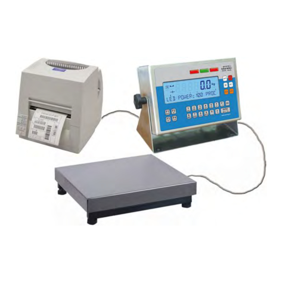
1. INTENDED USE Scales with PUE C41H terminal are industrial scales with a possibility of working in high humidity and a wide temperature range -10÷40°C. The terminal is equipped with fields of LEDs (light emitting diodes). Tarring within the whole range of measurement allows to determine the net mass of loads. -
Page 8: Precautionary Measures
2. PRECAUTIONARY MEASURES 2.1. Precautions A. Please, read carefully this user manual before and use the device according to its intended use. B. Devices that are to be withdrawn from usage should be sent back to the producer or in case of own utilization do it according to the law. 2.2. -
Page 9: Operation In A Strong Electrostatic Field
2.3. Operation in a strong electrostatic field If the device is about to operate in a strong electrostatic field (e.g. printing houses etc.) it should be connected to the earthing. Connect it to the clamp terminal signed 2.4. Washing scales intended for meat processing industry Weighing platforms are made of stainless steel (according to standards PN–0H18N9, EN-1.4301, AISI–304) and silicon elements. - Page 10 To wash waterproof platform scales and indicators/terminals neither jet of water nor hot water shall be used, in order not to damage the silicon gaiter that covers the load cell inside the platform and the overlay or glands in the indicator/terminal. To wash pans of platform scales they should be taken off first.
-
Page 11: Warranty Conditions
3. WARRANTY CONDITIONS A. RADWAG is obliged to repair or change those elements that appears to be faulty because of production and construction reason, B. Defining defects of unclear origin and outlining methods of elimination can be settled only in participation of a user and the manufacturer representatives, C. -
Page 12: Main Dimensions
4. MAIN DIMENSIONS Main dimensions of PUE C41H 5. DESCRIPTON OF CONNECTORS Terminal connectors 1 – I/O connectors 2 – RS232, RS485 connector 3 – Tensometer gland 4 – Power supply gland 5 – Earthing terminal 6 – Additional platform gland (option) 7 –Ethernet gland (option) 8 –... -
Page 13: Unpacking And Mounting
Notice: In accordance to the number of mounted modules the number and the placement of glands and connectors can vary. Connectors and glands mentioned in the standard solution appears in every option in the same place regardless of the option. 6. -
Page 14: Keyboard
8. KEYBOARD 9. PICTOGRAMS Pictogram Description Zero indication (Autozero zone) Equilibrium kg (g) Weighing mode Battery/accumulator Tare has been introduced Lower threshold Proper mass Upper threshold or TOP mode Counting pcs Weighings in percents ► Animals weighings (right side if the display) ►... -
Page 15: Battery Charge Indication
9.1. Battery charge indication pictogram is situated in the upper right corner informs about the discharge level or charging process: • pictogram blinks: accumulator damaged or no accumulator, • pictogram displayed continuously: it is charge between 70% and100%, • pictogram displayed continuously: it is charge between 30% and70%, •... -
Page 16: Menu - Parameters
Selection purpose variables … Work mode selection Log out Inscribing thresholds (MIN, MAX) Statistics view … Programmable … Caution: After pressing , functions of keys change while in the menu. The way of using them is described below. 11. MENU - PARAMETERS 11.1. - Page 17 P 1.2.1 FITER AVERAGE P 1.2.2 MED. FILTER P 1.2.3 LO THRESH. 20 d P 1.2.4 TARE MODE STDRD P 1.2.5 BASIC UNIT P 1.2.6 AUTOZERO P 1.2.7 DOS. FILTER P 1.3 FACTORY NO P 2 COM PORTS PARAMETERS P 2.1 RS 485 P 2.1.1 BAUD RATE 9600 P 2.1.2 DATA BITS...
- Page 18 P 3.5 ADDITIONAL DISPLAY P 3.5.1 DISPL. PORT P 3.5.2 DISPL. TYPE P 4 DATA / CZAS P 4.1 POKAŻ CZAS * FUNKCJA * P 4.2 USTAW CZAS * FUNKCJA * P 4.3 FORMAT DAT. YY-MM-DD P 5 PRINTOUTS P 5.1 AUTO. PRINT WHEN STAB P 5.2 STAB.
- Page 19 P 7.4.6.2 START CORRECTIONS 0.000 P 7.4.6.3 MAX CORRECTIONS 0.000 P 7.4.6.4 AVERAGING VALUE P 7.5 LABELLING P 7.5.1 C. LABEL P 7.5.2 CC LABEL P 7.5.3 N 1 P 7.5.4 M 1 0.000 P 7.5.5 N 2 P 7.5.6 M 2 0.000 P 7.5.7 EAN POINT.
-
Page 20: Navig Ting Within The Menu Level
* FUNCTION * P 10.1.2 CALIBRATION P 10.2 PLATF. 2 CALIB * FUNCTION * P 10.2.1 STRT M. ADJ * FUNCTION * P 10.2.2 CALIBRATION 11.2. Navigating within the menu level Use keyboard to browse the menu. 11.2.1. Keyboard Entering the main menu, special characters in the editing field Entering the search procedure of records in databases Moving up (left) Moving down (right) -
Page 21: Quick Access
11.2.2. Quick access It is possible to move quickly within the parameters’ menu using Procedure: 11.3. Return to weighing Press , until you see SAVE CHANGES ?. Then you press: – confirms changes or – skips changes. Then the scale returns to weighing. - 21 -... -
Page 22: Weighing
12. WEIGHING Put a load you want to weigh on the weighing pan. When the pictogram appears it means that the result is stable and ready to read. 12.1. Operating conditions In order to assure long-term operation and appropriate measurements of weighted loads following precautions should be taken into consideration: •... -
Page 23: Tarring
• Avoid side loads, particularly side shocks should be avoided: 12.2. Tarring In order to determine the net mass put the packaging on the pan. After stabilising press - (Net pictogram will be displayed in the left upper corner and zero will be indicated). After placing a load on the weight pan net mass will be shown. -
Page 24: Zeroing
• Press • In the lower line you will see an editing field: • Inscribe the tare value: • Press • The scale return to weighings mode The inscribed tare value can be seen on the display with „–” sign. Tare can be inscribed anytime in weighings mode. -
Page 25: Weighings In Two Ranges
12.5. Weighings in two ranges Switching between the I range and the II range happens automatically (exceeding Max of the I range). Weighings in the second range is signalled by a pictogram in the top left corner of the display. Then weighings is done with the accuracy of the II range to the moment of returning to zero (autozero range ) where the scale switches back... -
Page 26: Toggling Between Weight Units
Selection: • When the main unit is [kg], users can select among: [kg, lb, oz, ct, N, g] , for verified scales [lb, oz, N] are not accessible; • When the main unit is [g], users can select among: [g, kg, lb, oz, ct, N] , for verified scales [lb, oz, N] are not accessible. -
Page 27: Main Parameters
13. MAIN PARAMETERS Users can adjust the scale to external ambient conditions (filtering level) or particular needs (autozero operation, tare memory). This parameters are present in <P1 SCALE PARAMETERS>. 13.1. Filtering level Procedure: • While in weighings mode press and then: Return to weighing: See 11.3. -
Page 28: Median Filter
13.2. Median filter This filter eliminates short mechanical shocks. Procedure: • Enter <P1 SCALE PARAMETERS> and then: - filter disabled YES - filter enabled Return to weighing: See 11.3. 13.3. Dosing filter setting In PUE 41 terminals an special averaging filter for dosing process has been implemented. - Page 29 As dosing is a kind of dynamic state, which results in continuous changes in measurements, the averaged number of samples in the filter have an effect on the result. An example situation is illustrated below: The upper blue line represents results for n=1 samples in the filter buffer (averaging is off).
-
Page 30: Minimal Mass Parameter
Procedure: • Enter <P1 SCALE PARAMETERS > according to 11.2. of the manual: Return to weighing: See 11.3. 13.4. Minimal mass parameter Parameter PROG LO is related to following functions: - automatic tare, - automatic operation, - weighing animals. The next automatic tarring can be performed after the indication reaches the gross value below LO THRESH. -
Page 31: Tare Function
Return to weighing: See 11.3. 13.5. Tare function This parameter allows to set appropriate parameters for tarring. Procedure: • Enter <P1 SCALE PARAMETERS> according to 11.2. and then: - 31 -... -
Page 32: Autozero
AUTO disable automatic tare (the mode is remembered after restart); NORMAL tarring by pressing tare memory mode - the last tare value is being kept MEMORY in a non-volatile memory, Net pictogram is displayed. sum of tares – summing up a product tare value with a tare from the database of tare values or with an inscribed one. -
Page 33: Ports Parameters
- Autozero disabled YES - Autozero enabled Return to weighing: See 11.3. 14. PORTS PARAMETERS It is possible to connect external devices (printer, computer) to the ports: • RS 232 (1) • RS 232 (2) • RS 485 • Ethernet Configuration can be done in: <P2 COM PORTS PARAMETERS>. -
Page 34: Baud Rate Of Rs 485
Return to weighing: See 11.3. 14.1.2. Baud rate of RS 485 Procedure: • Enter <P1 SCALE PARAMETERS> according to 11.2. and then: Return to weighing: See 11.3. - 34 -... -
Page 35: Rs 232 Parameters
14.1.3. RS 232 parameters Procedure: • Enter <P2.2 RS232 (1)> and press • Using scroll to <P2.2.2 DATA BITS> and press • The selected value confirm with • Using go to <P2.2.3 PARITY BIT> and press • The selected value confirm with •... -
Page 36: Setting Of Rs 485 Parameters
14.1.4. Setting of RS 485 parameters Procedure: • Enter <P2.1 RS485> and press • Using go to <P2.1.2 DATA BITS> and press • The selected value confirm with • Using go to <P2.1.3 PARITY BITS> and press • The selected value confirm with •... -
Page 37: Ethernet Setting
14.2. ETHERNET setting ETHERNET can be configured in <P2.4 ETHERNET>. Inventory of default parameters: NAME VALUE DESCRIPTION Ethernet connection as Server or Client. SERVER – scale waits for connection P2.4.1 WORK MODE SERVER, CLIENT CLIENT – scale initiates the connection to a HOST. -
Page 38: External Devices
Caution: 1. Installation version of EDYTOR WPW is accessible on the Internet: www.radwag.com. Look up: Products / Measuring indicators / PUE C41H. 2. Check chapter 32.2 for details on cooperation with EDYTOR WPW. 15.1.1. Select the communication port scale-computer The computer can be connected to: •... -
Page 39: Type Of Printout Scale - Computer
Caution: Standard scales can communicate with computers only via RS232(1) or RS485. Return to weighing: See 11.3. 15.1.2. Type of printout scale – computer Procedure: • Enter <P3 DEVICES> and then: - 39 -... -
Page 40: Address Setting
• Inscribe a value (0 to 254) and press Return to weighing: See 11.3. 15.1.4. Commands operating of communication protocol User in parameter <P3.1.4 BASIC TRS.> has possibility to set communication protocol designed to communicate between RADWAG scale and external device. - 40 -... -
Page 41: Cooperation With „E2R System
Procedure: • Enter < P3.1 COMPUTER > according to 11.2. and then: Return to weighing: See 11.3. 15.1.5. Cooperation with „E2R System” Scales can cooperate with computer software „E2R System” that is a modular system for complex production supervising by monitoring of weighings processes. -
Page 42: Buffer For Weighings
Return to weighing: See 11.3. 15.1.5.2. Buffer for weighings Users can declare the quantity of performed measurements to be saved in the internal buffer in the scale in case of operating OFF-LINE (no transmission to „E2R SYSTEM”). After reconnecting with „E2R SYSTEM” all measurements from the internal buffer will be sent to the database of the computer program. -
Page 43: The Lock Of Product Change
Return to weighing: See 11.3. 15.1.5.3. The lock of product change Users can lock changing products by scale operators cooperating with „E2R SYSTEM”. Procedure: • Enter < P3.1 COMPUTER > according to 11.2. and then: Return to weighing: See 11.3. 15.2. -
Page 44: Coop Ation With A Barcode Scanner
Procedure: • Enter <P3.2 PRINTER> and then: Return to weighing: See 11.3. 15.3. Cooperation with a barcode scanner The scale gives possibility to cooperate with barcode scanners. It is used for quick search of database of assortment. Caution: In <P2 COM PORTS PARAMETERS> set the baud rate for the same as your barcode scanner requires (default 9600b/s). -
Page 45: Setting The Start Parameter
Return to weighing: See 11.3. 15.3.2. Setting the START parameter Procedure: • Enter <P3.3 BARCODE SCANER> and then set the START parameter – a character number in barcodes that is to be analysed during the assortment database search: - 45 -... -
Page 46: Setting The Length Parameter
Return to weighing: See 11.3. 15.3.3. Setting the LENGTH parameter Procedure: • Enter <P3.3 BARCODE SCANER> and then set the LENGTH parameter – the number if character in barcodes (counting from START) that is to be analysed during the assortment database search: Return to weighing: See 11.3. -
Page 47: Selecting Of Communication Port
Caution: In parameters <P2 COM PORTS PARAMETERS> set the baud rate for the one that requires the barcode scanner (default 9600b/s). 15.4.1. Selecting of communication port In parameters <P3.4 TRANSP. CARD READER.> and then select a communication port with the transponder card reader: Return to weighing See 11.3. -
Page 48: Coop Ation With An Additional Display
• In parameters <P2 COM PORTS PARAMETERS> set the baud rate (default 9600b/s). • Enter the database of operators and then find and edit the required operator. Find <CARD CODE> field: • Approaching a card to the reader results in displaying the card number in the <CARD CODE>... -
Page 49: Selecting An Additional Display Type
Return to weighing: See 11.3. 15.5.2. Selecting an additional display type Procedure: • Enter < P3.5 ADDITIONAL DISPLAY > according to 11.2. and then: Return to weighing: See 11.3. - 49 -... -
Page 50: Date / Time Setting
16. DATE / TIME SETTING Enter <P4 DATE / TIME> to set these parameters. 16.1. Time view Procedure: Return to weighing: See 11.3. 16.2. Time setting Procedure • Enter the DATE / TIME> and then: - 50 -... -
Page 51: Date Format
• After pressing you will see: • Enter an appropriate value and confirm it with • You will have to enter the following variables in sequence: - MONTH - DAY - HOUR - MINUTE • After confirming the last value with you will see the current date and time: Return to weighing:... -
Page 52: Printouts
- year - month – day YY - MM - DD - year - day - month YY - DD - MM DD - MM - YY - day - month - year Return to weighing: See 11.3. 17. PRINTOUTS 17.1. -
Page 53: Printout Of Stable / Unstable Data
manual printout WHEN STB automatic printout after stabilising continuous printouts CONTIN. LAST STB printing the last stable result after taking of a load, before reaching the LO-. value ONE PRINT Single print over -LO- Automatic printout of each stable measurement EACH over the -LO- STABILE... -
Page 54: Checkweighing Mode
Procedure: • Enter <P5 PRINTOUTS> according to 11.2. and then: Return to weighing: See 11.3. Notice: In case of verified scales <P5.2 STAB. PRINT> is not accessible for users. 17.3. Checkweighing mode In this mode printout is possible only when the result is between Min, Max thresholds. -
Page 55: Non-Standard Printouts
Return to weighing: See 11.3. 17.4. Non-standard printouts Users have possibility to design non-standard printouts in <P5.4 PRINTOUT>. Procedure: • Enter <P5 PRINTOUTS> according to 11.2. and then: Return to weighing: See 11.3. 17.5. Designing non-standard printouts To create a non-standard printout: •... -
Page 56: Texts In Non-Standard Printouts
• After pressing , you will see a cursor. Software is ready to accept your data. Non-standard printout can comprise: • Constant texts, • Variables from different work modes (mass, date, thresholds etc.), • Non-standard printout design can include max. 320 characters, •... -
Page 57: Variables Appearance In All Modes
17.6.2. Variables appearance in all modes CODE DESCRIPTION %000 Mass in a basic unit of the active platform %001 Mass in a current unit of the active platform %002 Date %003 Time %004 Date and time %005 Calibration unit %006 Current unit %007 Min threshold (for checkweighing) -
Page 58: Variables For The Labelling Mode Only
%068 Gross mass EAN 128 %070 Date in EAN 128 %126 Reference quantity for counting pieces Difference of tare values (a product tare value subtracted %127 from present tare value) %128 Batch number (6 characters) %131 Dosing net mass in calibration unit %132 Present number of records in the weighing database %134... -
Page 59: Variables For Printing Out Weighings From The Database
%052 Net value %053 Net value for c labels %054 Net values for cc labels %055 Gross value %057 Expiration date (current date + number of days) %062 Net value in EAN 13 (6-character code) %063 Net value in EAN 13 (expanded 7-characters’ code for supermarkets) %065 Net mass for c label in EAN 128 %066... -
Page 60: Variables For Printouts Of Reports From Weighing
Caution: Remember that the name of a new printout design should have the following pattern: WGXX , where: XX – subsequent number of printout. 17.6.5. Variables for printouts of reports from weighing %086 Weighing status (threshold for weighing - MIN, OK or MAX) %087 Sum of weighings %088... -
Page 61: Special Characters That Can Be Used In Non-Standard Printouts
CRLF Tabulator End of printout Each of the four printouts can hold up to 320 characters (letters, digits, special characters, spaces). Example: „RADWAG” Date: Time: Mass: Signature:..The inscribed data for : “ R A D W A G ” \ C \ T D A T E : % 0 0 2 \ C \ T T I M E : % 0 0 3 \ C \ T M A S S : % 0 0 0 \ C \ C \ T \ T S I G N A T U R E : . -
Page 62: Dat Bases
18. DATABASES 18.1. Logging procedure In case of activating of logging procedure (submenu <P6.1 LOG IN>), an operator after switching on has to perform a jogging procedure which consists in inscribing a password. Operators can also use a transponder cards for this procedure provided the terminal is equipped in a transponder card reader (see 15.4). -
Page 63: Access Level
Caution: In case there are no data in the operators’ database press to skip the logging procedure and add at least one operator with the highest level access. If no ADMINISTRATORS are defined there will be no access to some functions designated only for administrators. 18.2. -
Page 64: Access Level For Disabled Logging
Notice: This setting is valid although standard logging is disabled. 18.2.2. Access level for disabled logging The scale program gives possibility to set an access level in case of disabling logging procedure. Procedure: • Enter <P6 DATABASES> and then: OPERATOR Can perform weighings, edit P1, P4, P9 parameters;... -
Page 65: Password Type
18.3. Password type It is possible to set the password type to inscribe. Procedure: • Enter <P6 DATABASE> according to 11.2. and then: only digits 0 to 9 alphanumeric password ALPHANUM Return to weighing: See 11.3. 18.4. Type of codes There is possible to select a type of codes. -
Page 66: Access To Edition Of Databases
only digits 0 to 9 ALPHANUM alphanumeric password Return to weighing: See 11.3. 18.5. Access to edition of databases Procedure: Return to weighing: See 11.3 - 66 -... -
Page 67: Quick Searching In Databases
Notice: Users can access different things in the menu according to their Access levels. It also concerns an access to databases. 18.6. Quick searching in databases Users can search databases using different criteria: • Code, • Name, • Record number. This procedure is applicable for: operators, assortment, materials and contractors. -
Page 68: Quick Name Search
Notice: If the search result is not successful the <NO RECORD> message in the bottom line is displayed for 1 second and then software returns to displaying the current record. Return to weighing: See 11.3. 18.6.2. Quick name search Procedure: •... -
Page 69: Quick Number Search
18.6.3. Quick number search Procedure: • While in any work mode press (select / view products in the assortment database), • Scale program displays the record number one in the bottom line: • Using numeric keys enter a required record number •... - Page 70 • Press to add an operator, • In the bottom line you will see the first line for inscribing data. • You can enter the edition end confirm any data by pressing You can select fields using Fields in an operator record: NAME Operator name (max.
-
Page 71: Assortment Database
• To edit a defined operator press • To delete all records press Return to weighing: See 11.3. 18.8. Assortment database The assortment database can comprise up to 3000 records. Procedure: • Enter databases according to 18.5 of this manual: •... - Page 72 Fields in the assortment database: NAME Product name (max. 40 characters) Product code (max. 7 characters) CODE Constant code that can be used as a barcode (max. 15 digits) NOMINAL MASS Nominal mass of a product Minimal mass for checkweighing Maximal mass for checkweighing Tare value (it is preset automatically after selecting TARE...
-
Page 73: Database Of Weighings
• To erase the selected record press • To edit the selected record press • To clear the database press Return to weighing: See 11.3. 18.9. Database of weighings Every result sent from the scale to a printer is also saved in the database of weighings. -
Page 74: Atabase Of Tare Values
• When the database is empty you will see: • In case when the database is not empty, you will see the first record (date, mass, unit): • To delete the selected record press • To delete all records press •... -
Page 75: General Purpose Variables
• To enter a tare value • Using numerical keys inscribe a value and confirm with • Press one more time to return to the weighing mode. You will see the entered value with „–”. • To delete a selected tare press •... -
Page 76: Editing General Purpose Variables
18.11.1. Editing general purpose variables Procedure: • Enter databases according to 18.5 and then: • To add or modify a record (inscribing characters like in mobile phones) press • To add or modify a record (inscribing only digits 0 to 9) press •... -
Page 77: General Purpose Variables In Printouts
Mass: signature:..Where: <„RADWAG”> is a universal variable No 3. After entering non- standard printouts (see 17.5) we design a printout: % 8 0 3 \ C \ T D A T E : % 0 0 2 \ C \ T T I M E : % 0 0 3 \ C \ T M A S S : % 0 0 0 \ C \ C \ T \ T S I G N A T U R E: . - Page 78 • In case the database is empty you will see: • Press to add a record, • You will see the first field for edition. • Entering edition and confirming changes can be made by pressing . Select fields to be changed using keys.
-
Page 79: Database Of Contractors
• Press to save changes, • You will see the product name you have edited: • To erase the selected record press • To edit the selected record press • To clear the database press Return to weighing: See 11.3. 18.13. - Page 80 • Press to add a record, • You will see the first field for edition. • Entering edition and confirming changes can be made by pressing . Select fields to be changed using keys. Fields in the contractors’ database: NAME Contractor name (max.
-
Page 81: Reports From Weighings
• To erase the selected contractor press • To edit the selected contractor press • To clear the database press Return to weighing: See 11.3. 19. REPORTS FROM WEIGHINGS Users can print reports from the series of weighings. Reports can be filtered according to: - start date, - end date, - operator code,... -
Page 82: Printout Of Reports
19.2. Printout of reports After entering editing (see ch. 19.1) you will see the following window: • To edit variables press • Confirm the changes by pressing • To filter according to the selected variable press and you will see the following window: •... -
Page 83: Configuration Of External Inputs / Outputs
• Using select one of four report patterns (report patterns description – see ch. 17.6.4), • Press to printout a report according to the selected pattern. Caution: If filtering according to all variables is disabled, the report from all the weighings will be printed out. Return to weighing: See 11.3. -
Page 84: Configuration Of Outputs
• Press • Confirm your selection with • Using go to the next parameter. Caution: You can ascribe all your buttons accordingly. Remember that the standard solution has only 3 inputs. Return to weighing: See 11.3. 20.2. Configuration of outputs Users can configure outputs according to their needs. -
Page 85: Sta Istics
• Press • Confirm the selected value with • Using go to the next function. Notice: You can ascribe all functions to outputs accordingly. Remember that the standard solution has only 3 reed relay outputs. Return to weighing: See 11.3. 21. -
Page 86: Printouts Of Statistics
GENERAL global statistics, statistics for every product. ASSORT Return to weighing: See 11.3. 21.2. Printouts of statistics Users can print out statistics in any work mode. Procedure: Using users can view the current statistics: SUM – total mass of all details, AVG – every mass of all details, MIN – minimal mass, MAX - maximal mass. -
Page 87: Zeroing Statistics
Printout example: N = 7 number of weighing S U M = 3 . 8 0 0 k g total mass A V G = 0 . 5 4 3 k g average mass of all loads M I N = 0 . 2 0 0 k g minimal mass M A X = 1 . -
Page 88: Other Parameters
Caution: 1. When a user changes a work mode all statistics are automatically deleted. 2. Statistic data are common from all platforms connected (no separate calculations). 22. OTHER PARAMETERS Users can set parameters that influence the weighings procedure. There are included in <P9 OTHER> e.g. language, backlight, BEEP sound. -
Page 89: Led Power Setting
22.2. LED power setting According to the requirements (e.g. intensity of external light) it is possible to change the light flux from LEDs in the scale of 0% to 100%. Procedure: • Enter <P9.2 DIODES> according to 11.2. and then: Return to weighing: See 11.3. - Page 90 diodes start to lit after exceeding RED LEDS NONSTAB. the LO threshold (see 13.3), RED LEDS STABLE diodes start to lit after exceeding the LO and reaching equilibrium, RED LEDS OFF diodes not work, diodes start to lit after exceeding the LO, GREEN LEDS NONSTAB.
-
Page 91: Automatic Power Down
22.4. Automatic power down Changes can be made in <P9.3 POWER SAVE>. When the POWER SAVE function is enabled the device switches off after 5 min. Provided no changes on the pan appeared (no changes on the display). Operation Function setting Mains Accumulator POWER SAVE = NO... -
Page 92: Backlight
22.5. Backlight According to the requirements (e.g. intensity of external light) it is possible to: • Switch on/off or set the backlight operation to AUTO – when supplied from mains, • Change the backlight intensity in the scale of 0% to 100% - when supplied from an accumulator (lower backlight intensity increases the operation time when supplied from the accumulator). -
Page 93: Backlight - Power Supply From The Accumulator
22.5.2. Backlight - power supply from the accumulator Procedure: • Enter <P9 OTHER> according to 11.2. and then: Return to weighing: See 11.3. Notice: Backlight operation shortens time between subsequent recharges of the accumulator. 22.6. “Beep” sound – key-press reaction Procedure: •... -
Page 94: Keypad Modes
- no “beep” after pressing keys - “beep” after pressing keys Return to weighing: See 11.3. 22.7. Keypad modes The program allows to chose between alphanumeric keypad modes for inscribing texts. Procedure: • Enter <P9 OTHERS> according to 11.2. and then: - 94 -... -
Page 95: Software Version View
2ABC Digits come first after pressing a key ABC2 Letters come first after pressing a key Return to weighing: See 11.3. 22.8. Software version view Users <P9.7 SOFT. VER.> can view a software version number. Procedure: • Enter <P9 OTHER> according to 11.2. and then: Return to weighing: See 11.3. -
Page 96: Calibration Procedure
23.1. Calibration procedure • Enter <P10 USER CALIB.> according to 11.2. and then: • Unload the pan, • Press . During adjusting a start mass you will see: ADJ. START MASS, in the bottom line, • After completing this procedure you will see the following window: •... -
Page 97: Start Mass Adjustment
23.2. Start mass adjustment It is possible to adjust only a start mass, it helps to correct the start zero when the span does not change. Procedure: • Enter <P10 USER CALIB.> according to 11.2. and then: • Unload the scale, •... -
Page 98: Work Modes
24. WORK MODES 24.1. Setting accessibility of work modes In the parameter <P7.1 ACCESSIBILITY> users can declare which work modes need to by accessible after pressing Procedure: • Enter <P7 WORK MODES> and then: - mode denied YES - mode accessible Return to weighing: See 11.3. -
Page 99: Programmable Keys
24.2. Programmable keys In parameter group <P7.2 KEY FUNCTIONS> users can ascribe different functions to keys: to get an easiest access to different functionalities. Procedure: • Enter <P7 WORK MODES> and then: • Using select a key to ascribe ( •... - Page 100 Edit non-standard printout No 3 EDIT. PRINTOUT 3 Edit non-standard printout No 4 EDIT. PRINTOUT 4 Quick search of the assortment database using ASSORTMENT CODE a product code Quick search of the assortment database using EAN ASSORT. CODE a product EAN code STAT.
-
Page 101: Control According To An Inscribed Standard Mass
Setting the number of CC labels to be printed CC LABELS NO Setting the recipe multiplier MULTIPLIER * RECIPE CODE * Inscribing a recipe code for a quick search of recipes Access to the database of reports from recipes RECIPE REPORT * (e.g. - Page 102 • Using numerical keys inscribe a MAX threshold and confirm with • Software returns to WEIGHING. While setting these thresholds following features are important: • Symbols: Min, OK, Max in the upper line of the display: • Designation of the proper interval (OK) on the bargraph: •...
-
Page 103: Maximal Force Latch
Caution: Users can use this function in other work modes like counting pieces, weighing in percents etc. Only values and units can change. 24.4. Maximal force latch Procedure: • Enter the TOP work mode: • TOP selection is signalled by the Max pictogram in the upper line of the display: •... -
Page 104: Enabling Work Modes
24.5.1. Enabling work modes • COUNTING PCS procedure is active when pictogram is displayed. 24.5.2. Setting standard mass by inscribing the mass of a single piece Procedure: • Enter COUNTING PCS and then: Press to initialise COUNTING PCS. with automatic setting of standard mass. -
Page 105: Setting The Standard Mass By Declaring The Quantity Of A Sample
24.5.3. Setting the standard mass by declaring the quantity of a sample Procedure: • Enter COUNTING PCS. and then: While inscribing a sample quantity it should be remembered that the mass of a single piece should not be lower than 0.1 d and the total mass of a sample (all pcs) should not be lower than 1 d. -
Page 106: Devia On In Percents In Relation To A Standard Mass
Notice: If a user confirms a sample with with the empty weight pan, <Err6> will be displayed. Return to weighing: See 11.3. 24.6. Deviation in percents in relation to a standard mass Software can help to control deviations (in %) from a standard (nominal) mass. -
Page 107: Inscribing A Standard Mass
• Put a load to be a standard mass on the weight pan, • After the equilibrium is reached ( ) press • You will see the indication of 100,00%, • From this moment all results will be displayed in percents: Return to weighing: See 11.3. -
Page 108: Weighing Animals
From this moment all results will be displayed in percents. Return to weighing: See 11.3. 24.7. Weighing animals 24.7.1. Weighing time setting Users can set in seconds the time of weighing an animal. During this time averaging is performed. Procedure: •... -
Page 109: Starting The Work Mode
24.7.2. Starting the work mode • WGH. ANIMALS mode is signalled by showing ► pictogram in the right side of the picture. 24.7.3. Procedure of weighing animals • After starting ANIM. WEIGH. (see 24.7.2) put the animal on the platform, •... -
Page 110: Dosin
24.8. Dosing Standard indicators are equipped with signalling fields and internal circuit of - 3 optoinsulated inputs (5÷24V DC), 3 optoinsulated reed relay outputs. Caution: 1. Working mode „Dosing” does not support continuous printouts; 2. Inductive loads connected to the dosing indicator should have protections against the coil induction phenomenon. -
Page 111: Time Interval Between Changing Dosage Thresholds
24.8.2. Time interval between changing dosage thresholds By setting <P7.4.2 DELAY> parameter users can set a delay time between changing dosing thresholds. Procedure: • Enter <P7 WORK MODES> and then: • Using numeric keys inscribe the required value (0 to 60 s) and confirm by pressing Return to weighing: See 11.3. -
Page 112: Mode For Outputs
Using numeric keys inscribe a requires value (0 to 60 s) and confirm by pressing Return to weighing: See 11.3. 24.8.4. Mode for OUTPUTS Software includes three different algorithms operating on OUTPUTS that allows the device to readjust to the customer’s requirements. Procedure: •... -
Page 113: Tarring Mode Setting
Caution: If dosing is initiated when the indication is > LO , after reaching the indication below LO output (outputs)will be automatically switched on. Subsequent dosing process can be started when indication goes below 24.8.5. Tarring mode setting The parameter <P7.4.5 TARRING> allows to enable/disable automatic tarring in DOSING mode. -
Page 114: Correction Mode
24.8.6.1. Correction mode Procedure: • Enter <P7 WORK MODES> and then: Correction function disabled NONE CONSTAN Dosing refered to a constant nominal value of correction AUTO enabling automatic correction Return to weighing: See 11.3. 24.8.6.2. Initial correction value In parameter <P7.4.6.2 START CORRECTION> a user can set a mass value to be subtracted from or added to the nominal mass. -
Page 115: Maximum Correctional Value
• Use the scale keyboard a starting correction value and confirm it by pressing Notice: 1. The starting correction value is estimated experimentally in at least 2 subsequent cycles of dosing; 2. In correction mode <CONSTANT>, the start correction is always the correction value, but in correction mode <AUTO>... -
Page 116: Averaging From Subsequent Dosing Cycles
Return to weighing: See 11.3. 24.8.6.4. Averaging from subsequent dosing cycles In parameter <P7.4.6.4 AVERAGING VALUE> users can set a number of subsequent dosing cycles to consider for calculating the correctional value. Averaging is always calculated form subsequent dosing cycles. Procedure: •... - Page 117 After entering the DOSING mode the pictogram is displayed. Press to start a dosing process. After starting it starts blinking, keyboard is blocked until the process is completed. The process completion is signalled by displaying a message: < END OF DOSING > in the bottom line of the display: This process can be stopped only by pressing .
-
Page 118: Labelling
32.3 of this manual. 2. Example ready-to-implement label patterns are accessible to download from our website: www.radwag.pl in the overlap Products/Weighing Indcators/ PUE C41 Indicator 24.9.1. Triggering off „C LABEL”... -
Page 119: Triggering Off „Cc Labels
Caution: After a c label is printed counter N2 is incremented and sum SUM 2 changes. Counter N1 and sum SUM 1 are zeroed. Return to weighing: See 11.3. 24.9.2. Triggering off „CC LABELS” Operators can use one of three ways to trigger off cumulative labels depending on <P7.5.2 CC LABEL>... -
Page 120: Setting „N1" Counter
24.9.3. Setting „N1” counter Procedure: • Enter <P7.4.3 N1> according to 11.2. • Inscribe the N1 value to be exceeded for triggering c label, • Confirm it with Return to weighing: See 11.3. 24.9.4. Setting „M1” mass value Procedure: • Enter <P7.4.3 M1> according to 11.2., •... -
Page 121: Setting „N2" Counter
24.9.5. Setting „N2” counter Procedure: • Enter <P7.4.5 N2> according to 11.2, • Inscribe N2 value to be exceeded for triggering cc label, • Confirm it with Return to weighing: See 11.3. 24.9.6. Setting „M2” mass value Procedure: • Enter <P7.4.6 M1> according to 11.2., •... -
Page 122: Point In Mass Form In Ean-13 Code
24.9.7. Point in mass form in EAN-13 code In common systems of retail EAN13 bar codes are used. The sellers use weights that shows mass in kilos with 3 places after dot accuracy. There are 5 places in the mass code. That makes impossible to use weights with 100 and more kilos range (2 places after dot is approved only). -
Page 123: Setting Of The Number Of Cumulative Labels To Print
Procedure: • Enter parameters group <P7 WORK MODES> following point 11.2. of the manual and then: • Using the keyboard enter the amount of labels to print and press Return to weighing: See – point 11.3 - return to weighing. 24.9.9. -
Page 124: Setting Of The Number Of Cc Labels To Print
Return to weighing: See ch. 11.3 - return to weighing 24.9.10. Setting of the number of cc labels to print In the parameter <P7.5.10 NO OF LAB. CC> define the amount of total sum labels to print. They are printed on connected printer. Procedure: •... -
Page 125: Description Of Labelling Procedure
Selecting the LABELLING operation mode is confirmed by continuous displaying ► pictogram in the right edge of the display. 24.9.12. Description of labelling procedure Notice: Before the labelling procedure please design and load the pattern of the label into the terminal memory. Chapter 32.3 of the manual presents the example of creating and downloading the label into the terminal memory and setting printer basic parameters to cooperate with the scale. -
Page 126: Printing Cumulative Labels
24.9.13. Printing cumulative labels Cumulative labels C LABELS can include summarized values of single weighings until the moment of printing this label. A cumulative label is sticked to the package with a number of goods with single labels on them that have been weight so far. Such a label can be printed only for products for which it has been designed. -
Page 127: Printing Cumulative Labels Of Cumulative Labels
24.9.14. Printing cumulative labels of cumulative labels CC labels holds data from the whole process of labelling of one product e.g. for marking pallets or big containers with goods. Cumulative labels of cumulative labels need to be defined for the product. There are three criteria of printing cc labels: •... -
Page 128: Diagrams Of Connection Cables
25. DIAGRAMS OF CONNECTION CABLES The scale in STANDARD version can cooperate with: • computers • slip printers KAFKA, EPSON, KYOLINE • label printers CITIZEN, ZEBRA, • external buttons PRINT, TARA, ZERO, • internal I/O module of 3 optoinsulated inputs / 3 reed relay outputs. Scale –... - Page 129 Scale – printer (CITIZEN, EPSON) cable Scale – Zebra printer cable Scale - 3IN/3OUT (RSTS-8-184/2M) cable - 129 -...
-
Page 130: Connectors
PRINT, TARA, ZERO external buttons cable 26. CONNECTORS Caution: In accordance to the number of mounted modules the number and the placement of glands and connectors can vary. Connectors and glands mentioned in the standard solution appears in every option in the same place regardless of the option. -
Page 131: Rs232, Rs485 Connector
• Description of connector 3IN/3OUT 3IN/3OUT connector Exemplary scheme of connections for inputs: Voltage for inputs: Max voltage for outputs: from 5V DC to 24V DC 24V 0,5A DC/AC 26.2. RS232, RS485 connector RS232, RS485 connector - 131 -... -
Page 132: Specification Of Additional Modules
27. SPECIFICATION OF ADDITIONAL MODULES Apart from standard interface, it is possible to equip terminals with additional module increasing functionality of devices: • ET - Ethernet module, • AN - analogue outputs module, • PK 1 - relay outputs module, •... -
Page 133: Ethernet Module - Et
Main board view with connectors for additional modules: – DP 1 module – Ethernet ET 1G, ET 1 D module – Relay module – WE 8 module – AN module 27.1. Ethernet module - ET Ethernet module PCB - 133 -... -
Page 134: Mounting Way In Pue C41H
This module is designed according to TCP/IP 10/100 Mbit/s standard. It comprises two signalling LED’s: • D2 lights - Ethernet connection established, • D1 blinks - transmission 10Mbit/s or 100Mbit/s. Module accessible in two versions: ET 1G : with external connector on the scale housing; ET 1D : with cable (twisted pair) about 3m length led out via the gland on the scale housing Intended for connecting to a switch (not computer). - Page 135 9. Connect the PT0014 cable to J2 and J3 connectors on the Ethernet module according to the description; 10. Cable (twisted pair) or wires from the Ethernet socket connect to the group of wires (unhook band clips fastening the group of wires, lay the cable or conductors from the socket and hook the band clips).
-
Page 136: Drawings Of Sockets And Cables For Ethernet
27.1.2. Drawings of sockets and cables for Ethernet Ethernet socket for ET 1G version Ethernet cable for ET 1D (version for a SWITCH) 27.2. Analogue output module Module of analogue outputs - 136 -... -
Page 137: Technical Specification
Module accessible in three configurations: • Voltage output AN 0-10V • Current output AN 4-20mA • Current output AN 0-20mA 27.2.1. Technical specification Work modes 4 - 20mA , 0 - 20mA, 0 - 10V Resolution 16 bit Current output resistance <500 Voltage output resistance >400... -
Page 138: Configuration Of Work Modes Of Analogue Modules
Mounting of AN module on the main board of PUE C41H 27.2.3. Configuration of work modes of analogue modules A work mode of analogue modules can be set using S1 switch according to the drawings above table „configuration of analogue modules ”). Near the S1 switch on the PCB you can find a description. -
Page 139: Connections To An Module
27.2.4. Connections to AN module Drawing of connections of voltage output: COLOURS OF WIRES Colour Signal Pink Gray Yellow +24V DC Green Drawing of connections of current loop: COLOURS OF WIRES Colour Signal White Gray Yellow +24V DC Green Cable for analogue output - 139 -... -
Page 140: Relay Module - Pk1
27.3. Relay module - PK1 Relay module PCB - PK1 This is an alternative solution for reed relay outputs present on the main board in the standard solution. The usage of this module excludes the usage of standard reed relay outputs. The advantage of using this module are the electrical parameters of contacts. - Page 141 Installing procedure: 1. Unplug the scale from mains; 2. Unscrew and take off the back wall of the housing; 3. Install your module in J3 on the main board; 4. During installation turn your attention to plastic columns. They should be placed one side in mounting holes in the main board and the other side in the mounted module PK1;...
-
Page 142: Drawing Of Cables And Outputs
27.3.3. Drawing of cables and outputs Relay outputs diagram: SIGNALS AND DESIGNATIONS OF CONDUCTORS Wire number Description OUT 1 OUT 2 OUT 3 OUT 4 5 (yellow - green) Common 27.4. WE 4 - 4 inputs / 4 outputs module WE 4 module comprises 4 optoinsulated inputs and 4 optoinsulated outputs of reed relays. -
Page 143: Installing Method In Pue C41H Indicators
27.4.2. Colours of cables for I/O INPUTS OUTPUTS wire number description wire number description IN 1 OUT 1 IN 2 OUT 2 IN 3 OUT 3 IN 4 OUT 4 10 (yellow - GND IN COMMON green) 27.4.3. Installing method in PUE C41H indicators WE 4 modules are equipped in two cables, one for inputs and one for outputs. -
Page 144: We 8 8 Inputs / 8 Outputs Module
Installing WE4 modules on the main board of PUE C41H 27.5. WE 8 - 8 inputs / 8 outputs module 8 inputs / 8 outputs PCB - WE 8 WE 8 modules can be connected as an alternative to the module of analogue output and relay module. -
Page 145: Technical Specification
27.5.1. Technical specification Parameters of outputs Quantity of outputs Type of outputs Reed operation contacts Wire diameter 0,14 - 0,5mm Maximal load-current contact capacity 0,2A DC Maximal forward voltage 50V DC Parameters of inputs Quantity of inputs Input type Optoinsulated Wire diameter 0,14 –... -
Page 146: I/O Diagram
A WE 8 module placement on the main board of PUE C41H 27.5.3. I/O diagram WE8 inputs diagram WE8 outputs diagram - 146 -... -
Page 147: Description Of Input Output Wires
27.5.4. Description of input output wires Signals led out with two cables10x0,5mm with numbered conductors. INPUTS OUTPUTS Wire number description Wire number description IN 1 OUT1 IN 2 OUT2 IN 3 OUT3 IN 4 OUT4 IN 5 OUT5 IN 6 OUT6 IN 7 OUT7... -
Page 148: Technical Specification
1µV Minimal tensometer impedance 90Ω Maximal tensometer impedance 1200Ω Tensometer excitation voltage Types of tensometers 4 or 6 wires + shield 27.6.2. Colours of wires RADWAG Designation of soldering Colour Designation pads on PCB’s. +INPUT brown + 5V -INPUT green... -
Page 149: Connecting Additional Platforms
27.6.3. Connecting additional platforms Connecting 6-wire tensometers - tensometer cable shield REF+ - “SENSE +” from tensometer (JP1 not soldered) REF- - “SENSE –“ from tensometer (JP2 not soldered) - “OUTPUT+” from tensometer - “OUTPUT-“ from tensometer - “INPUT+” from tensometer AGND - “INPUT-“... - Page 150 Connecting 4-wire tensometers - tensometer cable shield REF+ - solder jumper JP1 REF- - solder jumper JP2 - “OUTPUT+” from tensometer - “OUTPUT-“ from tensometer - “INPUT+” from tensometer AGND - “INPUT-“ from tensometer The rules of connecting shields from tensometer cable For assuring appropriate operation use the description below to connect the shield of the tensometer properly.
-
Page 151: Installing In Pue C41H Housing
platforms electrically platforms connected connected to indicators’ to indicators in metal metal housings e.g. housing via a cable only pillars, racks Load cells without internal shield POINT C connection to the tensometer body Load cells with internal shield connection to POINT C POINT C the tensometer body... - Page 152 4. During installation turn your attention to plastic columns. They should be placed one side in mounting holes in the main board and the other side in the mounted module DP1. Installing DP1 module on the main board of PUE C41H 5.
-
Page 153: Rs485 Led Out Via Rs 1D Gland
27.7. RS485 led out via RS 1D gland A version with the RS485 interface led out via a gland (in the standard solution RS485 is present in a socket). A 3m cable is led out through the gland. 27.7.1. Installing inside the PUE C41H housing 1. -
Page 154: Rs 485 - Pt0012 Cable Drawing
PT0012 cable connecting to the main board of PUE C41H 5. Connect the PT0012 shield to the housing (4mm screwed terminal on the back wall) 6. The cable connect to the group of wires (unhook band clips fastening the group of wires, lay the cable and hook the band clips). Band clips of multiple usage;... -
Page 155: Com Unication Protocol
28. COMMUNICATION PROTOCOL 28.1. General information A. A character protocol scale-terminal has been designed for communication between RADWAG scales and external devices via RS-232 interface. B. It consists of commands sent from an external device to the scale and a responses from a scale. -
Page 156: Respond Message Format
Set upper threshold Read lower threshold Read upper threshold Send all implemented commands Notice: 1. Each command have to be terminated in CR LF; 2. The best Policy for communication is not sending another command until the former answer has been received. 28.3. -
Page 157: Tarring
- command accepted and in progress Z_A CR LF - command comprehended but zero range overflow appeared Z_^ CR LF - command accepted and in progress Z_A CR LF - time limit for stable result exceeded Z_E CR LF - command comprehended but cannot be executed Z_I CR LF 28.4.2. -
Page 158: Set Tare Value
28.4.4. Set tare value Syntax: UT_TARE CR LF, where TARE – tare value Possible answers: UT_OK CR LF - command executed - command comprehended but cannot be executed UT_I CR LF ES CR LF - command not recognised (possible wrong tare format) Notice: This protocole uses the dot character as a decimal point for separating the decimal fraction part. -
Page 159: Send The Result Immediately In Basic Unit
28.4.6. Send the result immediately in basic unit Syntax: SI CR LF Possible answers: SI_I CR LF - command comprehended but cannot be executed at the moment - command accepted and in progress SI_A CR LF - mass value in basic unit is returned MASS FRAME Frame format: 7-15... -
Page 160: Send The Stable Result In Current Unit
- weighing platform number mass - 9 characters justified to the right unit - 3 characters justified to the left Example: Let us assume that both platforms are connected to indicator PUE C41H. S I A CR LF – computer command P 1 _ ? _ _ _ _ _ _ 1 1 8 . -
Page 161: Send The Result Immediately In Current Unit
28.4.9. Send the result immediately in current unit Syntax: SUI CR LF Possible answers: SUI_I CR LF - command comprehended but cannot be executed - command accepted and in progress SUI_A CR LF - mass value in current unit is returned immediately MASS FRAME Frame format: 7-15... -
Page 162: Switch Off Continuous Transmission In Basic Unit
28.4.11. Switch off continuous transmission in basic unit Syntax: C0 CR LF Possible answers: - command comprehended but cannot be executed C0_I CR LF C0_A CR LF - command comprehended and executed 28.4.12. Switch on continuous transmission in current unit Syntax: CU1 CR LF Possible answers: - command comprehended but cannot be executed... -
Page 163: Lock The Scale Keyboard
28.4.14. Lock the scale keyboard Syntax: K1 CR LF Possible answers: - command comprehended but cannot be executed K1_I CR LF K1_OK CR LF - command executed Caution: This command is not remembered after restart 28.4.15. Unlock the scale keyboard Syntax: K0 CR LF Possible answers: K0_OK CR LF –... -
Page 164: Set Upper Threshold
Possible answers: - command executed DH_OK CR LF - command not comprehended (wrong mass format) ES CR LF 28.4.19. Set upper threshold Syntax: UH_XXXXX CR LF, where: XXXXX – mass format Possible answers: UH_OK CR LF - command executed - command not comprehended (wrong mass format) ES CR LF 28.4.20. -
Page 165: Send All Implemented Commands
Mass - 9 characters justified to the right Unit - 3 characters justified to the left 28.4.22. Send all implemented commands Syntax: PC CR LF Possible answers: PC_A_”Z,T,S,SI,SU,SUI,C1,C0,CU1,CU0,PC,K1,K0,DH,UH, ODH,OUH,S1,S0,OT,UT" – command executed, the indicator have sent all the implemented commands. 28.5. -
Page 166: Continuous Transmission
Example 1: _ _ _ _ _ _ 1 8 3 2 . 0 _ g _ _ CR LF – the printout generated from the scale after pressing ENTER/PRINT. Example 2: ? _ - _ _ _ _ 2 . 2 3 7 _ l b _ CR LF - the printout generated from the scale after pressing ENTER/PRINT. -
Page 167: Error Messages
29. ERROR MESSAGES ERROR ”XXX” ESC – RETURN TO PREVIOUS SETTING (where: XXX – parameter name) – confirmed with ENTER of a wrong value in the user’s menu, Value beyond the zero range, Err2 Value beyond the tare range, Err3 Calibration mass or start mass adjustment error Err4 (±1% for weight, ±10% for start mass),... -
Page 168: Technical Parameters
31. TECHNICAL PARAMETERS 31.1. Labelling scales WPW/E WPW/E WPW/E WPW/E WPW/E Scale type: 6 C1/K 15 C1/K 30 C1/K 60 C2/K Max capacity 15kg 30kg 60kg Readability Tare range -6kg -15kg -30kg -60kg Pan size 290 × 360mm 400 × 500mm Work temperature - 10°C to +40°C... -
Page 169: Labelling Scales Wpw/E/H
31.2. Labelling scales WPW/E/H WPW/E WPW/E WPW/E WPW/E WPW/E Scale type: 3 H1/K 6 H2/K 15 H2/K 15 H3/K 30 H3/K Max capacity 15kg 15kg 30kg Readability Tare range -3kg -6kg -15kg -15kg -30kg Pan size 150 × 200mm 250 × 300mm 410 ×... -
Page 170: Appendix
LCD with backlight 32. APPENDIX 32.1. Communication with barcode scanners 1. For communication with barcode scanners RADWAG scales use RS232 interfaces and simplex transmission (one direction) without handshaking. Only two wires are required for assuring such a transmission. Used scanners should be equipped in such interface with disabled both hardware and software handshaking. -
Page 171: Coop Ation With „Edytor Wpw" - Pc Software Tool
5. A special protocol is required in order the code be received by RADWAG equipment. It is required to program an appropriate prefix and suffix. Prefix – one byte 01 hexadecimally, suffix one byte 0D hexadecimally. 6. Most barcode scanners allow to enable/disable different symbologies (barcode types). -
Page 172: Main Window
32.2.1. Main window Caution: The installation file of EDYTOR WPW is accessible on RADWAG website www.radwag.com. In Products /Measuring indicators / PUE C41H. 32.2.2. Setting parameters of RS232 On order to establish the connection with EDYTOR WPW through RS232 interface follow the remarks below: •... -
Page 173: Setting Ethernet Parameters
• In the overlap <Transmission settings>: − Set the communication mode as „RS232 transmission”, − Select an appropriate com number, − Configure the selected port (baud rate, parity, data bits, stop bits), • Confirm the changes by clicking • Rerun the program, •... - Page 174 • Connect the scale to a computer/switch using a PT0017 or PT0014 cable (depending on the Ethernet module on board – see ch. 27.1.2), • Set the port for communication with a computer – parameter <P3.1.1 COMP. PORT> set to Ethernet (see ch. 15.1.1), •...
-
Page 175: Creati G And Downloading Label Patterns To The Terminal Memory
EDYTOR WPW software. Notice: Installation files of software EDYTOR ETYKIET R02 and EDYTOR WPW can be downloaded from our website: www.radwag.com. in: Products / Measuring indicators / PUE C41H. Example: Lets make and send following example of label into a terminal: 32.3.1. - Page 176 Notice: Prior to designing a label a new project needs to be created with initial printer and label settings. A description of creating new projects can be found in instruction manual „Label Editor R02” accessible in the program menu: „Info / User manual”. 2.
- Page 177 5. From list <Variable> chose variable type „4 Date and time” and press , then the variable is placed in the table of variables show below. 6. Confirm it by pressing , then the variable is automatically placed on the label. 7.
- Page 178 9. Chose one and press <Open>, then the image is placed on the label. Notice: Graphic images placed on the label can be printed only when they are downoladed to the printer memory. It is described in the instruction manual „Label Editor R02” accessible in the program menu on the overlap: „Info / User manual”.
-
Page 179: Downloading Labels' Patterns To Terminals
Notice: Recorded templates of labels in files with *.lb extension are not editable. This is advisable to record designs of labels in files with *.lab extension as well (software menu: File / Save as…) to use/edit the designs of labels in the future. 32.3.2. - Page 180 4. Give the label a name and code. Notice: The most important think is adequate assignation code to a product from the assortment database. The <code>placed in edition window must be the same as the one placed in <Label code> in edition window of assortment: 5.
-
Page 181: Citizen Printer Setting
8. Record the patern of the label in the scale memory by click on 9. Then labelling procedure can be started according to ch. 24.9.12 of the manual. 32.3.3. CITIZEN printer setting Baud rate : 9600b/sec Parity control : No Number of data bits : 8bit Number of stop bits... -
Page 182: Zebra Printer Setting
Serial port : 96, N, 8, 1 The way of generating the setup printout and setting ZEBRA (Eltron) printers are described in manuals attached to printers or present on the website of the manufacturer. 32.4. Example of designing non-standard printouts „RADWAG” DATE: TIME: MASS: SIGNATURE:.. - Page 183 Procedure of designing the report pattern: 1. Run program EDYTOR WPW and initiate communication with the scale according to ch. 32.2 of this manual, 2. Open database „labels” at: Databases/Databases/Labels. Press to upload data from the scale: 3. Edit one of the existing report patterns (*RP01*, *RP02*, *RP03* or *RP04*) - 183 -...
- Page 184 %130--------------------------------- Number of weighings: %089 Sum of weighings: %087 Description of applied variables: RADWAG WAGI ELEKTRONICZNE – company name (header) %129 The name of present record for the complex report %130 Marking the line for beginning printing weighings in the complex report.
-
Page 185: Examples Of Surge Protections
32.6. Examples of surge protections • Connection diagram of dosing indicators outputs with protection for DC: - 185 -... - Page 186 • Connection diagram of dosing indicators outputs with protection for AC: - 186 -...
- Page 187 O F E L E C T R O N I C W E I G H I N G I N S T R U M E N T S PRODUCENT WAG ELEKTRONICZNYCH ,,RADWAG” 26 – 600 Radom, Bracka 28 Street POLAND Phone +48 48 38 48 800, phone/fax.
Need help?
Do you have a question about the WPW/E and is the answer not in the manual?
Questions and answers