RADWAG WPY User Manual
Hide thumbs
Also See for WPY:
- User manual (188 pages) ,
- User manual (304 pages) ,
- User manual (124 pages)
Table of Contents
Advertisement
Quick Links
Advertisement
Table of Contents

Related Manuals for RADWAG WPY


Summary of Contents for RADWAG WPY
- Page 2 NOVEMBER 2020...
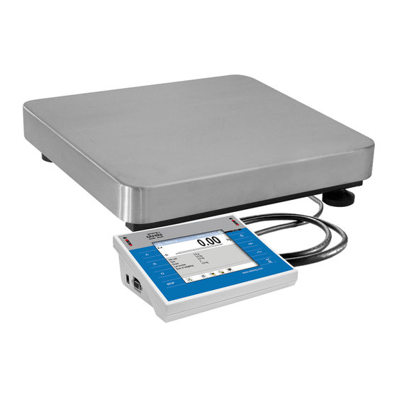
- Page 3 SERIES: Weighing pan Model dimensions WPY 0,6/D2 0.6kg 0.2g 195x195mm WPY 1,5/D2 1.5kg 0.5g 195x195mm WPY 1,5/F1 1.5kg 0.5g 300x300mm WPY 1,5/F1/K 1.5kg 0.5g 300x300mm WPY 1,5/F1/R 1.5kg 0.5g 300x300mm WPY 3/D2 195x195mm WPY 3/F1 300x300mm WPY 3/F1/K 300x300mm WPY 3/F1/R...
- Page 4 150kg 500x700mm WPY 150/C3/K 150kg 500x700mm WPY 300/C2 300kg 100g 400x500mm WPY 300/C2/K 300kg 100g 400x500mm WPY 300/C2/R 300kg 100g 400x500mm WPY 300/C3 300kg 100g 500x700mm WPY 300/C3/K 300kg 100g 500x700mm For detailed technical specifications refer to RADWAG website www.radwag.com.
- Page 5 PRECAUTIONS Prior to installation, use or maintenance activities, carefully read this user manual. Use the PUE 7.1 Indicator only as intended. Prior to the first use, carefully read this user manual. Use the device only as intended. Place loads in the centre of the weighing pan. Load the weighing pan with loads of gross weight which does not exceed the maximum capacity.
-
Page 6: Table Of Contents
6.5. Operation Panel............................13 7. INSTALLATION ..............................14 7.1. UNPACKING AND INSTALLATION......................14 7.1.1. WPY/D2 Series..........................14 7.1.2. WPY/F1, WPY/C2, WPY/C3 Series ....................14 7.2. Levelling..............................15 7.3. Start-Up ..............................15 8. HOME SCREEN ............................... 15 8.1. Top Bar ..............................16 8.2. -
Page 7: Intended Use
USB flash drive). 2. WARRANTY CONDITIONS A. RADWAG feels obliged to repair or exchange all elements that appear to be faulty by production or by construction. B. Defining defects of unclear origin and means of their elimination can only... -
Page 8: Cleaning Abs Components
In case of any sign of damage, it is necessary to disconnect the device form the mains immediately. The damaged component must be replaced or repaired by RADWAG service directly. In case of any problems with correct operation of the scale, contact the closest manufacturer's service point. -
Page 9: Recycling
5. RECYCLING WPY scales must be recycled, they are not to be treated as a regular household waste. Scales to be decommissioned must be decommissioned in accordance with valid legal regulations. -
Page 10: Dimensions
6.1. Dimensions Dimensions of WPY/D2 scale Dimensions of WPY/F1/R scale Dimensions of WPY/F1/K scale Dimensions of WPY/C2/R scale... -
Page 11: Connectors
Dimensions of WPY/C2/K scale Dimensions of WPY/C3/K scale 6.2. Connectors 1 – Ethernet RJ45 connector 1 – power supply socket 2 – RS232 (COM1) connector 2 – I/O, RS232 (COM2) connector 3 – USB connector 6.3. RS232 Connector RS232 - DB9/M connector (male), front:... -
Page 12: Inputs / Outputs
RS232 - DSUB15/F connector (female), front: Pin8 - TxD2 Pin9 - 5VDC Pin10 - GND Pin13 - RxD2 6.4. Inputs / Outputs Standard C32 scale is equipped with 4 optoisolated inputs and 4 semiconductor outputs (solid-state relays). The signals are fed through connector. -
Page 13: I/O Schematic Diagrams
6.4.2. I/O Schematic Diagrams 4 inputs 4 outputs 6.5. Operation Panel Keys Press to switch the scale ON/OFF. Press to zero the scale. Press to tare the scale. Press to send the weighing result to a printer or a computer. Press to enter the menu (function button). -
Page 14: Installation
C. Install the weighing pan and the indicator holder in accordance with the figure below: 7.1.2. WPY/F1, WPY/C2, WPY/C3 Series Take the device out of the packaging. Place the device on a flat and even surface. Keep it far away from any sources of heat. -
Page 15: Levelling
Mind to keep the key pressed for about 0.7 s. Operation system and RADWAG program are loaded, this is signalled with blinking of red ON/LOAD diode. Upon completed start-up, the home screen is displayed automatically. -
Page 16: Top Bar
Home screen layout: 8.1. Top Bar The top bar displays the following information: Working mode name and symbol. Log-in entry. Symbol informing that communication with a PC is on. ® Symbol informing that Wi-Fi connection is on. Symbol informing that communication with E2R SYSTEM is on. Device name. -
Page 17: Workspace
8.3. Workspace The workspace is to be found underneath the weighing result window. The workspace comprises 3 display templates. Graphics at the top inform which of the 3 templates is currently displayed. In order to switch to a different template drag the workspace screen to the left/right respectively. 8.4. -
Page 18: Return To Weighing
Press to search a particular database record by date. Press to search a particular database record by name. Press to search a particular database record by code. Press to print a database record. Press to export control and average tare reports for PGC and SQC modes. Press to export dosing and formulation reports. - Page 19 Load the weighing pan steadily, avoid applying mechanical shocks. Place the loads centrally on the weighing pan (eccentricity errors are specified by EN 45501 standard, point 3.6.2). In case of eccentric loading make sure that: a) mass of load placed close to one of the pan edges does not exceed ½...
-
Page 20: Diagrams Of Connection Cables
11. DIAGRAMS OF CONNECTION CABLES Scale - computer cable (RS232) Scale - printer cable (ZEBRA) Scale - printer cable (EPSON) -
Page 21: Error Messages
I/O cable „Scale-Ethernet” cable is a standard network cable terminated with RJ45 connectors on both ends. 12. ERROR MESSAGES...
Need help?
Do you have a question about the WPY and is the answer not in the manual?
Questions and answers