
Related Manuals for Network Technologies IPDU-Sx


Summary of Contents for Network Technologies IPDU-Sx
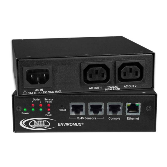
- Page 1 ® ENVIROMUX Series IPDU-Sx Secure Remote Power Reboot Switch Installation and Operation Manual Front and Rear View of IPDU-S2 Front and Rear View of IPDU-S8-P15 MAN119 Rev Date 4/22/14...
- Page 2 Network Technologies Inc, 1275 Danner Drive, Aurora, Ohio 44202. CHANGES The material in this guide is for information only and is subject to change without notice. Network Technologies Inc reserves the right to make changes in the product design without reservation and without notification to its users.
-
Page 3: Table Of Contents
TABLE OF CONTENTS IPDU-Sx................................... 1 Secure Remote Power Reboot Switch ........................1 Installation and Operation Manual..........................1 Introduction..................................1 Materials ..................................2 Supported Web Browsers ............................... 2 Features and Functions..............................3 Installation ..................................5 Connect AC Power Cables ............................5 Ethernet Connection .............................. - Page 4 Figure 6- LEDs on front of IPDU-S4/S8 ............................. 7 Figure 7- Cascade installation- RS485 Connection ........................... 8 Figure 8- Connect a GSM modem ..............................8 Figure 9- Secure rack mount ears to IPDU-Sx........................... 9 Figure 10- Secure IPDU-Sx to rack ..............................9 Figure 11- Device Discovery Tool..............................13...
- Page 5 Figure 13- Summary page ................................15 Figure 14- Summary page and the Monitoring menu........................16 Figure 15- Status page for a power outlet............................16 Figure 16- Power Outlet Configuration page............................ 17 Figure 17- More settings for Power Outlet Configuration ......................... 18 Figure 18- Line Monitor Categories ..............................
- Page 6 Figure 64- Text Menu Login screen ..............................58 Figure 65- Text Menu- Administrator Main Menu..........................59 Figure 66- Text Menu- Main Administrator Menu in IPDU-S4/-S8 ....................60 Figure 67- Text Menu- User Main Menu ............................60 Figure 68- Text Menu-Monitoring Menu............................61 Figure 69- Text Menu-Power Outlet Status............................
- Page 7 Figure 115- Text Menu-User Contact Settings..........................92 Figure 116- Text Menu-User Activity Schedule..........................93 Figure 117- Text Menu-Security Configuration ..........................94 Figure 118- Text Menu-Authentication Settings..........................94 Figure 119- Text Menu-IP Filtering ..............................95 Figure 120- Text Menu-Configure IP Filter rule..........................96 Figure 121- Text Menu-Event &...
-
Page 8: Ipdu-Sx
NTI Secure Remote Power Reboot Switch INTRODUCTION The ENVIROMUX® IPDU-Sx Secure Remote Power Reboot Switch allows you to remotely reboot and control power (ON/OFF) or to schedule periodic power cycles to servers or other powered devices from any location via secure web interface, RS232, SSH, or Telnet. -
Page 9: Materials
NTI Secure Remote Power Reboot Switch MATERIALS Materials supplied with this kit • NTI IPDU-Sx Secure Remote Power Reboot Switch • 1- IEC320-C13 Line cord, country specific (PS4162) (IPDU-S2 and IPDU-S4/8-P10 only) • 1- IEC320-C14 Output cord (PS4163) (IPDU-S2 and IPDU-S4/S8-P10 only) •... -
Page 10: Features And Functions
NTI Secure Remote Power Reboot Switch FEATURES AND FUNCTIONS IPDU-S2 1. LED Indicators • "POWER" (green) — indicates device is powered • "OUTLET" (green / red) — outlet is ON (green) or OFF (red) • "SENSOR FAULT" (red) — illuminates if a sensor goes out of range of a configurable threshold •... - Page 11 8. Circuit Breaker- 15A Circuit breaker for protection of the devices powered by the IPDU-Sx 9. Cascade- RJ45 Female- for cascading multiple IPDU-S4 and IPDU-S8 units 10. LED Display- for displaying the total AC current being supplied by the AC outlets on the IPDU-Sx...
-
Page 12: Installation
INSTALLATION Connect AC Power Cables The IPDU-Sx may be connected to a 100-240VAC power supply. A 120V power cord with NEMA 5-15 connector is provided for connection to a power supply. The AC outlets (“AC OUT 1” and “AC OUT 2”) are rated for up to 10A @ 120/240VAC and the combined maximum load cannot exceed 10A for IPDU-S2, IPDU-S4/S8-P10, or 15A for IPDU-S4/S8-P15. -
Page 13: Terminal Connection For Rs232
NTI Secure Remote Power Reboot Switch Terminal Connection for RS232 To make a direct serial connection to the IPDU-Sx from a terminal with HyperTerminal via RS232, an RJ45 female DCE port labeled "Console" is provided. Connect a CAT5 patch cable (supplied) between the port labeled “Console” and a PC with a terminal program (e.g. -
Page 14: Front Panel Leds Indicate Status
Front Panel LEDs Indicate Status With proper connections made, the IPDU-Sx is now ready to use. With the power cord attached and plugged into an AC outlet, the “Power” , “Outlet 1” and “Outlet 2” green LEDs should be illuminated on the front of the IPDU-S2. -
Page 15: Cascaded Installation Via Rs485 Connection
A GSM modem that has been tested and is confirmed to be compatible with the IPDU-S4/ -S8 is the iCON 452. To order this modem, contact NTI and ask for the ENVIROMUX-3GU. Figure 8- Connect a GSM modem Note: The modem connected to the IPDU-Sx will send SMS messages only. No access to the IPDU-Sx is possible through the modem. -
Page 16: Rack Mounting Instructions
Figure 9- Secure rack mount ears to IPDU-Sx Install 4 cage nuts to the rack in locations that line up with the holes in the mounting ears on the IPDU-Sx. Secure the IPDU-Sx to the rack using four #10-32x3/4” screws and cage nuts (provided). Be sure to tighten all mounting screws securely. -
Page 17: Overview
NTI Secure Remote Power Reboot Switch OVERVIEW Administration The IPDU-Sx can be administered in any one of the following ways: • Using a terminal program (e.g. HyperTerminal) via an RS232-Link, connected to Console Port. • Using Telnet or SSH protocol via the Ethernet Port. - Page 18 IP address status is considered to be “OK”’. The user will have the option to configure the IPDU-Sx to cycle power at the corresponding device’s outlet if no response is received, and an alert will be logged and sent.
-
Page 19: Security
IP Filtering The IPDU-Sx allows the administrator to block access to the device from certain IP addresses. The IPDU-Sx can accept or drop requests based on the IP filter settings. IP Filtering provides an additional mechanism for securing the IPDU-Sx. Access to the IPDU-Sx network services (SNMP, HTTP(S), SSH, Telnet) can be controlled by allowing or disallowing connections from various IP addresses, subnets, or networks. -
Page 20: Device Discovery Tool
To Refresh the list of devices, click on the Refresh button. To Blink the LEDs of the unit, click on the Blink LED button (This feature is not supported on the IPDU-Sx.) The Blink LED button will change to a “Blinking….” button. The LEDs of the unit will blink until the Blinking… button is clicked on, or the NTI Device Discovery Application is closed. -
Page 21: Operation Via Web Interface
OPERATION VIA WEB INTERFACE A user may monitor and configure the settings of the IPDU-Sx, the outlets, and any sensor connected to it using the Web Interface via any web browser (see page 2 for supported web browsers). To access the Web Interface, connect the IPDU-S2 to the Ethernet (page 5). -
Page 22: Monitoring
With a successful log in, the “Summary” page with a menu at left will appear on the screen: Figure 13- Summary page From this initial page, the user can use the menu to the left to manage all the functions of the IPDU-Sx. Function... -
Page 23: Figure 14- Summary Page And The Monitoring Menu
From the Summary page, the user can view the status of all power outlets, sensors, and the IP Devices being monitored by the IPDU-Sx. Each item listed has a link that when selected will open the status page for that item. -
Page 24: Configure A Power Outlet
NTI Secure Remote Power Reboot Switch Configure a Power Outlet The Power Outlet Configuration page allows the user to apply settings to control how or if alert messages are sent in the event the outlet changes state. The user can open the Power Outlet Configuration page by clicking on the Configure button at the bottom of the Power Outlet Status page (page 16) or by clicking on Edit from the Summary page. -
Page 25: Figure 17- More Settings For Power Outlet Configuration
NTI Secure Remote Power Reboot Switch This field only found in IPDU-S4 and IPDU-S8 Figure 17- More settings for Power Outlet Configuration... - Page 26 (if one event is configured to turn the outlet OFF, and another event to turn the outlet ON, this setting will decide the state of the outlet) Note: Alerts are also indicated by illuminated LEDs on the front of the IPDU-Sx (page 7). More about Groups Groups are used to create a common relationship between sensors, IP devices, power outlets, etc.
-
Page 27: Line Monitor
NTI Secure Remote Power Reboot Switch Line Monitor The Line Monitor on the Summary Page provides a quick way to view the amount of power that is being used by the IPDU-S4 or IPDU-S8. From the Summary Page the user will find displayed: •... -
Page 28: Figure 19- Configuration Categories
NTI Secure Remote Power Reboot Switch Each category of line monitoring is configurable much like sensors are configured. For more on configuration, see “Monitor and Configure Sensors” on next page. Figure 19- Configuration Categories... -
Page 29: Monitor And Configure Sensors
NTI Secure Remote Power Reboot Switch Monitor and Configure Sensors To view the graphic image showing the status of a sensor, click on the sensor description in the Summary page. From the sensor status page, the user can view a current reading, either dismiss or acknowledge an alert, or open the sensor configuration page (if the user has administrative privileges). -
Page 30: Figure 22- Sensor Configuration- Full View Of Settings
NTI Secure Remote Power Reboot Switch The Sensor Configuration page is broken into four sections; Sensor Settings, Alert Settings and Data Logging, and Power Outlet Association. To explode the window to see settings for a section, click on the section heading (Figure 21). This field only found in IPDU-S4 and IPDU-S8 Figure 22- Sensor Configuration- full view of settings... - Page 31 NTI Secure Remote Power Reboot Switch Sensor Settings Description Description The description of the sensor that will be viewed in the Summary page and in the body of alert messages Group Assign the sensor to either group 1 or 2 (see also page 45) Units This lets the operator choose between Celsius and Fahrenheit as the temperature measurement unit.
-
Page 32: Monitor Ip Devices
NTI Secure Remote Power Reboot Switch Monitor IP Devices IP devices such as servers, routers, cameras, etc. can be monitored to make sure network connections are open to them. In order to monitor an IP Device the devices must be added to the list of IP Devices being monitored. From the Monitoring section of the menu, click on IP Devices. -
Page 33: Figure 25- Ip Device Configuration Page
NTI Secure Remote Power Reboot Switch The IP Device Configuration page will immediately open. Here you can configure the IPDU-Sx to ping the IP Device as often as desired and to react to a lack of response by sending alert messages and/or power-cycling a power outlet. -
Page 34: Figure 26- Power Outlet Association For Ip Device
NTI Secure Remote Power Reboot Switch Figure 26- Power Outlet Association for IP Device With a couple of IP devices having been configured for monitoring, the IP Device list will provide links to them for viewing their status, editing their configuration, or deleting them from the list. Figure 27- IP Device list with new devices added To view the graphic image showing the status of an IP address, click on the IP Device description or click View. -
Page 35: Monitor Events
NTI Secure Remote Power Reboot Switch Monitor Events The IPDU (models IPDU-S4 and IPDU-S8 only) can be configure to respond to predefined events. Once the criteria is set for what constitutes an event, an alert can be sent and/or devices connected to outlets can be controlled. Up to 50 events can be configured. -
Page 36: Figure 32- List Of Configured Event
NTI Secure Remote Power Reboot Switch Once events are configured, they are listed and numbered for monitoring and easy adjustment. Up to 50 can be configured. Figure 32- List of Configured Event If an event is triggered, the Status will change from “Normal” to “Alarm”. Whatever reaction that has been configured as a result of this event will be activated. -
Page 37: Administration
Fields for assigning the unit name, address, contact person, the IPDU-S2 e-mail address, and phone number of a contact person Network Fields for providing all the network settings the IPDU-Sx including IP address, DNS, SMTP and SNMP settings Cascade Fields for configuring this IPDU to control multiple IPDUs or be controlled by... - Page 38 NTI Secure Remote Power Reboot Switch The Date and Time of the IPDU-Sx can be either manually setup to use an onboard clock or set to be synchronized with an NTP server. The configuration of the IPDU-Sx can also be easily backed up to a file on your PC and restored from that file as needed.
-
Page 39: Enterprise Configuration
The modem will work with a signal strength between -111dBm (weak) and -51dBm (strong). If a modem is not installed, the words “not available” will be displayed instead for the modem type. Note: It may take several minutes for the GSM modem to be detected by the IPDU-Sx. GSM modem is properly installed... -
Page 40: Network Configuration
DHCP server (default setting), or manually fill in the fields (use a static address). To view the Network Configuration page, click on Network from the Administration section of the menu. Note: When “DHCP” is selected, make sure a DHCP server is running on the network the IPDU-Sx is connected to. Note: The values shown here are for local (static) address configuration only. -
Page 41: Figure 37- Network Configuration- More Settings
NTI Secure Remote Power Reboot Switch The Network Configuration page is broken into seven sections; IP Settings, SMTP Settings, SNMP Settings, Server Settings, and IP Alias 1, 2,and 3 Settings. To explode the window to see settings for a section, click on the section heading. Common Port numbers: Default: 25 (Not secure) - Page 42 IPDU-Sx using SNMP network management software or a MIB browser and MIB file (MIB file version 1.01 or later). This name must be present in the IPDU-Sx AND in the proper field in the SNMP software. This name is case sensitive so be sure to enter it correctly in the IPDU-Sx as well as in the SNMP software.
-
Page 43: Figure 38- Ip Aliases
NTI Secure Remote Power Reboot Switch Figure 38- IP Aliases IP Aliases Only applicable to IPDU-S4/S8- Firmware version 1.4 or later Up to 3 IP aliases can be configured. This provides added flexibility when access from multiple networks is required. To use an alias, be sure to change the default Mode to “Enable”. -
Page 44: Figure 39- Setup Snmp To Control Output Relays
NTI Secure Remote Power Reboot Switch 1. Configure the IPDU (Network Settings) Note: enter same values from IPDU to the MIB browser (private) (public) 2. Configure the MIB browser 4. Identify which Output to 3. Expand the tree to view the change state (power On or relay output values (right click power Off), right click and... -
Page 45: Cascade Configuration
RS485 or Ethernet connection. When using the RS485 Connection method for cascading the IPDU-Sx will be connected as shown on page 8. If units will be controlled using the Ethernet Connection method, the IPDU-Sx will be connected to a network using the “ETHERNET” port. -
Page 46: Figure 41- Configure As Rs485 Slave
NTI Secure Remote Power Reboot Switch RS485 Slave If the type is RS485 Slave, an address number (1-255) must be entered to identify the unit to the master. Each slave on the system must have a unique address number. Figure 41- Configure as RS485 Slave Ethernet Slave If the type is Ethernet Slave, the Ethernet address entered on the Network Configuration page (page 33) will be used by the master to communicate with this slave. -
Page 47: Figure 43- Configure As Rs485 Master
NTI Secure Remote Power Reboot Switch RS485 Master If the type is RS485 Master, then the RS485 addresses for each slave (valid address range of 1-255) must be entered into the available blocks (up to 16) in order to communicate between the master and each slave. Once an RS485 address has been entered, and the RS485 slave has been properly configured to be cascaded as part of this system, place a checkmark in the “Enable Slave”... -
Page 48: Figure 44- Configure As Ethernet Master
NTI Secure Remote Power Reboot Switch Ethernet Master If the type is Ethernet Master, then the Slave IP Address Settings must be entered for each slave that will be controlled. The IP address will be used by the master to locate and communicate with the slave. Once an IP address has been entered, and the Ethernet slave has been properly configured to be cascaded as part of this system, place a checkmark in the “Enable Slave”... -
Page 49: Figure 45- Cascade Notification Settings
NTI Secure Remote Power Reboot Switch Cascade Notification In the event a slave goes offline from the system, the system can be set to notify those configured to receive messages from the master unit. In the Cascade menu under Administration, the “Cascade Notification Settings” menu provides a place to configure how frequent notifications will be repeated. -
Page 50: User Configuration
The Users page is a list of all configured users of the IPDU-Sx. A maximum of 15 users (other than root) can be configured. From this page the user can choose to add more users, go to the user configuration page to edit a user’s access to the IPDU-Sx, or delete a user from the list. -
Page 51: Figure 48- Configure User- More Options
Admin Place a checkmark here if this user should have administrative privileges Enabled Place a checkmark here to enable this user to access the IPDU-Sx Password Enter a password that a user must use to login to the system A password must be assigned for the user’s login to be valid Passwords must be at least 1 keyboard character. - Page 52 NTI Secure Remote Power Reboot Switch LDAP Account Settings “Common Name” assigned in the LDAP server account in an Active Directory. Often a name Common Name (for LDAP) assigned that is different than the Username. If this is the same as the Username in the “Account Settings”...
-
Page 53: Figure 49-Summary Page For User Without Admin Privileges
NTI Secure Remote Power Reboot Switch More about User Privileges The root user (or any user with administrator rights) can change the root password and configure how the root user will receive alert messages. Users with administrative rights can change all configuration settings except for the root user name. Users with user rights can only see the current readings of monitored items and change their own passwords. -
Page 54: Security
LDAP server. To view the Security Configuration page, select Security in the Administration section of the menu. Figure 50- Security Configuration page When in LDAP mode, usernames on the LDAP server must match those in the user settings of the IPDU-Sx or access will be denied. -
Page 55: Figure 51- Security Configuration-X509 Certificate And Login Alerts
X509 Certificate The IPDU-Sx is pre-loaded with a generic X509 Server Certificate. If you wish to provide your own X509 Server certificate, the Server certificate must be uploaded to the ENVIROMUX. The Server certificate and key must be combined in a single file (“PEM”... -
Page 56: Figure 52- Security Configuration- Ip Filtering Rules
Login Alert Settings The IPDU-Sx can be configured to send an alert to users in either group 1 or group 2 when a user logs in or when someone attempts to login but fails to enter a correct password. To disable this feature, just select “Disable Alerts”. -
Page 57: System Information
192.168.1.100, we need to configure and enable an ACCEPT rule at the top of the list: Then, to block all other IP addresses from connecting to the IPDU-Sx, we add a rule to drop all other connections. If the preceding “drop all connections” rule was placed in position one, no connections at all would be allowed to the unit. -
Page 58: Update Firmware
Update Firmware The Update Firmware page is used to change the firmware of the IPDU-Sx. Occasionally new features or changes to existing features will be introduced and new firmware with these changes will be made available on the NTI website (http://www.networktechinc.com/download/d-secure-power.html). -
Page 59: Reboot The System
The IPDU-Sx can be remotely rebooted by anyone with administrative privileges. To view the Reboot System page, select Reboot in the Administration section of the main menu. Click the Reboot Now button to cause the IPDU-Sx to reboot. This will disconnect any user and shut down all activity. -
Page 60: Log
View Event Log The Event Log provides the administrative user with a listing of many events that occur within the IPDU-Sx. The event log will record the date and time of: •... -
Page 61: View Data Log
View Data Log The Data Log provides the administrative user with a listing of all the readings taken by the IPDU-Sx pertaining to the sensors and IP Devices being monitored. The event log will record the date and time of each reading. -
Page 62: Figure 59- Log Settings Page
GSM modem for receiving SMS messages (page 8), and/or to make the log file portable by connecting a USB flash drive. The IPDU-S4 or IPDU-S8 will record event and data logs to a USB flash drive in addition to the internal IPDU-Sx memory when the feature is enabled. -
Page 63: Figure 61- Enable Usb Port
2. Place a checkmark in the “Enable Log to Flash drive” box found on the Log Settings page (Figure 61). Note: If the flash drive is not connected before enabling the feature, the IPDU-Sx will not recognize the flash drive. -
Page 64: Support
You must have Adobe Reader installed on your PC to open this. The Downloads link will take you to the Firmware Downloads page for the IPDU-Sx on the NTI website. All versions of firmware and MIB files for the IPDU-Sx will be found there, available for immediate download to your PC. -
Page 65: Operation Via Text Menu- Ipdu-Sx
The IPDU-Sx can be controlled using a terminal program (e.g. HyperTerminal) via an RS232-Link, connected to Console Port (page 6) or using Telnet or SSH protocol via the Ethernet Port. Either of these methods will work to access the IPDU-Sx text menu. -
Page 66: Connect To Ipdu-Sx From Command Line
NTI Secure Remote Power Reboot Switch Connect to IPDU-Sx from Command Line To connect directly to a serial port from the command line, the IPDU-Sx must first be connected to the Ethernet (page 5). Connect Via Telnet To open a telnet session to the IPDU-Sx, Issue the following command from the command line: telnet <IPDU-Sx hostname or IP address>... -
Page 67: Figure 66- Text Menu- Main Administrator Menu In Ipdu-S4/-S8
NTI Secure Remote Power Reboot Switch Then main menu in the IPDU-S4 and IPDU-S8 has an additional category of “Cascade Configuration. For more on Cascading, see page 85. Extra feature only in the IPDU-S4 and IPDU-S8 Figure 66- Text Menu- Main Administrator Menu in IPDU-S4/-S8 If you are a user with only user privileges (no administrative privileges), the text menu will have more limited options. -
Page 68: Using The Text Menu
Enables the user to reboot the IPDU-SX Monitoring The Monitoring menu lists choices for viewing the status of items monitored by the IPDU-Sx as well as for configuring how they are monitored and how or if alert messages will be sent. -
Page 69: Figure 69- Text Menu-Power Outlet Status
ON/OFF state. To change its state, select the outlet and press <Enter>. Use the <Tab> or <Arrow> keys to move between Cancel, Turn ON, Turn OFF, or Cycle to power cycle the IPDU-Sx. If Cycle is selected, the IPDU-Sx will power cycle the outlet based on the configuration settings found under Power Outlet Configuration. -
Page 70: Figure 71- Text Menu- Line Monitor Parameters
The View Line Monitor Parameters selection (IPDU-S4 and IPDU-S8 only) will show the present status of each characteristic of the power being provided by the IPDU-Sx to the outlets. In the image below, not only is the power through the master being monitored, but the power through each slave. -
Page 71: Figure 73- Text Menu-Configure Power Outlets
NTI Secure Remote Power Reboot Switch Configure Power Outlets The Configure Power Outlets menu lists the power outlets in the IPDU-Sx. Press <Enter> to open the configuration menu for the selected Power Outlet. Figure 73- Text Menu-Configure Power Outlets The configuration menu for the Power Outlet includes options to enter the Power Outlet Settings, Notification Settings, and Outlet Operation Settings. -
Page 72: Figure 75- Text Menu-Power Outlet Settings
NTI Secure Remote Power Reboot Switch Power Outlet Settings From the Power Outlet Settings menu enter the Description for the outlet and select which sensor group the outlet should belong to (1 or 2). Figure 75- Text Menu-Power Outlet Settings Power Outlet Notification Settings From the Notification Settings menu, the user can enable/disable alert messages to be sent when the power outlet state changes and configure if and how alert messages are sent. -
Page 73: Figure 77- Text Menu-Power Outlet Operation Settings
NTI Secure Remote Power Reboot Switch Alert Settings Disable alerts Change to “Yes” to prevent notifications from being sent when this outlet is in an alert state Enable Email Alerts Change to “Yes” to have alert notifications sent via Email Enable Syslog Alerts Change to “Yes”... -
Page 74: Figure 78- Text Menu-Configure Sensors List
Mode will change the operating mode to Manual Mode until the outlet is reconfigured. Configure Sensors The Configure Sensors menu lists the sensors connected to the IPDU-Sx. Press <Enter> to open the configuration menu for the selected sensor. Figure 78- Text Menu-Configure Sensors list... -
Page 75: Figure 79- Text Menu-Configuration Menu For Sensor
NTI Secure Remote Power Reboot Switch The configuration menu for the sensor includes options to enter the Sensor Settings, Alert Settings, and Data Logging, Power Outlet Association Settings. Figure 79- Text Menu-Configuration Menu for Sensor From the Sensor Settings menu enter the Description for the sensor and select which sensor group the sensor should belong to (1 or 2). -
Page 76: Figure 81- Text Menu-Sensor Alert Settings
NTI Secure Remote Power Reboot Switch Sensor Settings Description Description The description of the sensor that will be viewed in the Summary page and in the body of alert messages Group Assign the sensor to either group 1 or 2 (see also page 45) Units This lets the operator choose between Celsius and Fahrenheit as the temperature measurement unit. - Page 77 NTI Secure Remote Power Reboot Switch Alert Settings Disable alerts Change to “Yes” to prevent alerts from being sent when this sensor’s status changes Alert Delay The alert delay is an amount of time the sensor must be in an alert condition before an alert is sent.
-
Page 78: Figure 82- Text Menu-Sensor Data Logging
NTI Secure Remote Power Reboot Switch From the Data Logging menu for the sensor, the user can decide if the data sampled should be recorded in the Data Log and how frequently. Figure 82- Text Menu-Sensor Data Logging From the Power Outlet Association menu for the sensor, the user can configure the functionality of a power outlet associated with a sensor’s operation. -
Page 79: Figure 84- Configure Line Monitor Parameters
Configure Line Monitor Parameters Each of the line parameters for the power going through the outlets on the IPDU-Sx (IPDU-S4 and IPDU-S8 only) can be configured just as the sensors are configured (page 67) to send alerts, log data, and control power outlets. -
Page 80: Figure 86- Text Menu-Configure Ip Devices List
NTI Secure Remote Power Reboot Switch Configure IP Devices The Configure IP Devices menu lists the IP Devices monitored by the IPDU-SX. Press <Enter> to open the configuration menu for the selected IP Device. Figure 86- Text Menu-Configure IP Devices List The configuration menu for the IP Device includes options to enter the IP Device Settings, Alert Settings, and Data Logging, Power Outlet Association Settings. -
Page 81: Figure 88-Text Menu-Ip Device Settings
Under Power Outlet Association, if the IP device is connected to one of the power outlets on the IPDU- Sx, the IPDU-Sx can automatically cycle the power to the chosen outlet when the IP device is determined to be in a state of alarm. -
Page 82: Figure 89- Text Menu-Ip Device Alert Settings
NTI Secure Remote Power Reboot Switch From the Alert Settings menu, the user can enable/disable alert messages to be sent when the IP Device is not responding and configure when and how alert messages are sent. Figure 89- Text Menu-IP Device Alert Settings Alert Settings Disable alerts Change to “Yes”... -
Page 83: Figure 90- Text Menu-Ip Device Data Logging
From the Power Outlet Association menu for the IP Device, the user can configure which power outlet is associated with a IP Device’s operation. If the IP device is connected to one of the power outlets on the IPDU-Sx, the IPDU-Sx can automatically cycle the power to the chosen outlet when the IP device is determined to be in a state of alarm. -
Page 84: System Configuration
On the Time Settings menu, the user can designate what time zone the unit is associated with, set the date and time manually or configure the IPDU-Sx to get this information from an NTP server. Figure 93- Text Menu-Time Settings menu... -
Page 85: Figure 94- Text Menu-Restore Default Settings
Select this option to restore the IPDU-Sx to the configuration settings it had upon receipt from the factory. Be careful! This will erase all user configuration settings. Upon restoration, the IPDU-Sx will reboot. Allow 1 minute before trying to reconnect and log in again. -
Page 86: Enterprise Configuration
Under Enterprise Configuration (from the Main Menu), enter the unit name, location, the contact person emails should refer to and their phone number, and the email address of the IPDU-Sx to be used for outgoing alert messages. Figure 95- Text Menu-Enterprise Configuration... -
Page 87: Figure 97- Text Menu-Ip Settings Menu
NTI Secure Remote Power Reboot Switch IP Settings The IP Settings menu contains the network connection settings for the IPDU-Sx. Figure 97- Text Menu-IP Settings Menu IP Settings Description Mode Select between Static (manual) , or DHCP (automatic IP and DNS) settings... -
Page 88: Figure 98- Text Menu-Smtp Server Settings
Use Authentication Change to “Yes” if the SMTP server requires authentication to send email Username Enter a valid username to be used by the IPDU-SX to send emails Password Enter a valid password assigned to the IPDU-SX username Note: The SMTP server port number is shown in Figure 96 as "25". -
Page 89: Figure 99- Text Menu-Snmp Server Settings
The SNMP Read-Write community name enables a user to read information from the IPDU-Sx and to modify settings on the IPDU-Sx using the SNMP browser and MIB file. This name must be present in the IPDU and in the proper field in the SNMP... -
Page 90: Figure 100- Text Menu-Misc. Service Settings Menu
The administrator may assign a different HTTP Server Port than is used by most servers (80). Note: If the port number is changed and forgotten, to determine what it has been changed to connect the IPDU-Sx for RS232 control (page 6) and review these settings. -
Page 91: Figure 101- Text Menu- Ip Alias Settings
NTI Secure Remote Power Reboot Switch IP Aliases (Applicable only to IPDU-S4 and IPDU-S8 models.) Figure 101- Text Menu- IP Alias Settings Up to 3 IP aliases can be configured. This provides added flexibility when access from multiple networks is required. To use an alias, be sure to change the default Mode to “Enable”. -
Page 92: Cascade Configuration
Units can be cascaded using either RS485 or Ethernet connection. When using the RS485 Connection method for cascading the IPDU-Sx will be connected as shown on page 8. If units will be controlled using the Ethernet Connection method, the IPDU-Sx will be connected to a network using the “ETHERNET”... -
Page 93: Figure 103- Text Menu- Unit Rs485 Address
NTI Secure Remote Power Reboot Switch RS485 Slave If the type is RS485 Slave, an address number (1-255) must be entered to identify the unit to the master. Each slave on the system must have a unique address number. Figure 103- Text Menu- Unit RS485 Address Ethernet Slave If the type is Ethernet Slave, the Ethernet address entered on the Network Configuration page (page 33) will be used by the master to communicate with this slave. -
Page 94: Figure 105- Text Menu- Rs485 Master's Slave List
NTI Secure Remote Power Reboot Switch RS485 Master If the type is RS485 Master, then the RS485 addresses for each slave (valid address range of 1-255) must be entered into the available slots (up to 16) in order to communicate between the master and each slave. The RS485 unit address and Slave IP address settings will not apply to this configuration. -
Page 95: Figure 107- Text Menu- Ethernet Master's Slave List
NTI Secure Remote Power Reboot Switch Ethernet Master If the type is Ethernet Master, then the Slave IP Address Settings (item 2 in the Cascade Configuration menu) must be entered for each slave that will be controlled. RS485 address settings and the RS485 unit address will not apply. To configure a slave to be connected, select the desired slave number and press <Enter>... -
Page 96: Figure 109- Text Menu-Cascade Notification Settings
NTI Secure Remote Power Reboot Switch Cascade Notification In the event a slave goes offline from the system, the system can be set to notify those configured to receive messages from the master unit. Selecting 5 from the “Cascade Configuration” menu will open the “Cascade Notification” menu where you can specify how frequent notifications will be repeated. -
Page 97: User Configuration
NTI Secure Remote Power Reboot Switch User Configuration The User Configuration menu lists all configured user names of the IPDU-Sx. A maximum of 15 users (other than root) can be configured. From this screen the administrative user can add users, go to the user configuration page to edit a user’s access to the IPDU-Sx, or delete a user from the list. -
Page 98: Figure 113- Text Menu-Configuration List For User
NTI Secure Remote Power Reboot Switch Figure 113- Text Menu-Configuration List for User User Account Settings Select “Account Settings” from the list and press <Enter>. A menu with the account settings for that specific user will open where you can either leave the name as “userx”, or change it. With the name assigned, fill in the remaining information as needed. -
Page 99: Figure 115- Text Menu-User Contact Settings
NTI Secure Remote Power Reboot Switch Account Settings Description Enabled Change to “Yes” to enable this user to access the IPDU-Sx Admin Change to “Yes” if this user should have administrative privileges Title Enter information as applicable (optional) Department Enter information as applicable (optional) -
Page 100: Figure 116- Text Menu-User Activity Schedule
NTI Secure Remote Power Reboot Switch User Activity Schedule Select “Schedule” from the list and press <Enter>. A menu with the user activity settings for that specific user will open. Figure 116- Text Menu-User Activity Schedule Schedule Settings Schedule Type Always active- user will receive messages at all hours of each day Active during defined times- user will only receive alert messages during times as outlined below... -
Page 101: Security Configuration
Select “Authentication Settings” from the list and press <Enter>. A menu providing an option to either user Local authentication or LDAP mode. When in LDAP mode, usernames on the LDAP server must match those in the user settings of the IPDU-Sx or access will be denied. -
Page 102: Figure 119- Text Menu-Ip Filtering
IP addresses, subnets, or networks. Up to 16 IP Filtering rules can be defined to protect the IPDU-Sx from unwanted access from intruders. Each rule can be set as Enabled or Disabled. Rules can be set to explicitly drop attempts to connect, or to accept them. -
Page 103: Figure 120- Text Menu-Configure Ip Filter Rule
192.168.1.100, we need to configure and enable an ACCEPT rule at the top of the list: (Rule 1) Enabled: Yes Rule type: ACCEPT IP/mask: 192.168.1.100 Then, to block all other IP addresses from connecting to the IPDU-SX, we add a rule to drop all other connections. (Rule 16) Enabled: Yes Rule type: DROP IP/mask: 0.0.0.0/0 If the preceding “drop all connections”... -
Page 104: Event And Data Logs
NTI Secure Remote Power Reboot Switch Event and Data Logs Under the Event and Data Logs menu find 4 submenus for viewing a log record of the events monitored by the IPDU-Sx and configuring how the IPDU-Sx will handle reaching the capacity of those logs. -
Page 105: Figure 123- Text Menu-View Data Log
View Data Log The Data Log provides the administrative user with a listing of all the readings taken by the IPDU-Sx pertaining to the sensors and IP Devices being monitored. The data log will record the date and time of each reading. -
Page 106: Figure 124- Text Menu-Event Log Settings
NTI Secure Remote Power Reboot Switch Figure 124- Text Menu-Event Log Settings Figure 125-Text Menu-Data Log Settings... -
Page 107: System Information
Log to USB The USB Port found on the IPDU-S4 and IPDU-S8 enables the user to make the event and data log files portable. The IPDU-Sx will record event and data logs to a USB flash drive in addition to the internal IPDU-Sx memory when the feature is enabled. -
Page 108: Reboot
From the Main Menu the administrative user can initiate a reboot of the IPDU-Sx. By highlighting “Reboot” and pressing <Enter> (or <9> and <Enter>), you will be prompted to confirm that you want to reboot the IPDU-Sx. Press <Enter> to cancel, or press the <Tab>... -
Page 109: Text Menu For Non-Administrative Users
Users without administrative privileges are able to view sensors, IP Devices, and power outlets and edit their own account settings. Figure 129- Text Menu-User Main Menu Monitoring The Monitoring menu lists 3 options for viewing the status of the items monitored by the IPDU-Sx. Figure 130-Text Menu-User Monitoring Menu... -
Page 110: Figure 131- Text Menu-User Accessible Status Menus
NTI Secure Remote Power Reboot Switch Figure 131- Text Menu-User accessible status menus If a monitored item is in alert status, the non-administrative user can enter a response to it. By pressing the <Enter> key with the sensor selected, the user will have the option to either acknowledge the alert or dismiss it. If the user acknowledges the alert, no additional alert messages will be sent during that alert status cycle. -
Page 111: User Accessible Settings
NTI Secure Remote Power Reboot Switch User Accessible Settings The User without administrative privileges has access to setting for their own account. Figure 132- Text Menu-User Accessible Settings Account Settings Under Account Settings, the non-administrative user can edit their password, title, company, or department settings. Other settings are only accessible to the administrative user. -
Page 112: Figure 134- Text Menu-User Contact Settings
NTI Secure Remote Power Reboot Switch Contact Settings Under Contact Settings, the non-administrative user can decide which sensor group messages they will receive and how. Figure 134- Text Menu-User Contact Settings Contact Settings Group 1 Change to “Yes” to receive messages from sensors, IP devices and outlets in Group 1 Group 2 Change to “Yes”... -
Page 113: Figure 135- Text Menu-User Activity Schedule
NTI Secure Remote Power Reboot Switch Schedule Under Schedule, the non-administrative user can edit their activity schedule to control when messages should be sent to them. Figure 135- Text Menu-User Activity Schedule Schedule Settings Schedule Type Always active- user will receive messages at all hours of each day Active during defined times- user will only receive alert messages during times as outlined below Day of Week-From:... -
Page 114: Reset Button
A Reset push-button is on the front-panel and is recessed from the panel to prevent accidental use of the button. Pressing the Reset button will cause the IPDU-Sx to restart, just as if it were power-cycled. The Reset push-button has to be pressed and held for minimum of 7-10 seconds in order to activate the reset function. -
Page 115: Wiring Methods
PC-to IPDU-Sx Crossover Cable In order to make a direct connection between a PC and the ETHERNET connector of the IPDU-Sx (all models), a crossover cable must be used. The cable is made with CAT5 cable terminated with RJ45 connectors and wired according to the chart below. -
Page 116: Technical Specifications
NTI Secure Remote Power Reboot Switch TECHNICAL SPECIFICATIONS Sensor Inputs Two RJ45 modular jacks for connecting NTI temperature, humidity, temperature/humidity, and liquid detection sensors. Ethernet Port One female RJ45 connector with LEDs. 10 BaseT Ethernet interface. Console Port One female RJ45 connector. Supports 3-wire interface (Tx, Rx, and GND) AC Outlet connectors IEC 320-C13 10A @ 120/240VAC... -
Page 117: Troubleshooting
NTI Secure Remote Power Reboot Switch TROUBLESHOOTING Each and every piece of every product produced by Network Technologies Inc is 100% tested to exacting specifications. We make every effort to insure trouble-free installation and operation of our products. If problems are experienced while installing this product, please look over the troubleshooting chart below to see if perhaps we can answer any questions that arise. -
Page 118: Index
NTI Secure Remote Power Reboot Switch INDEX acknowledge, 16, 29, 62, 63, 103 monitoring-text menu, 61 Administration, 30, 53 monitoring-web interface, 15 Network configuration, 79 authentication, 94 cable connections, 5 Network Configuration, 33 cascade notification, 42, 89 operating modes, 19 cascaded installation, 8 overview, 10 cascading-text menu, 38, 85... -
Page 119: Warranty Information
NTI Secure Remote Power Reboot Switch WARRANTY INFORMATION The warranty period on this product (parts and labor) is two (2) years from the date of purchase. Please contact Network Technologies Inc at (800) 742-8324 (800-RGB-TECH) or (330) 562-7070 or visit our website at http://www.networktechinc.com for information regarding repairs and/or returns.
Need help?
Do you have a question about the IPDU-Sx and is the answer not in the manual?
Questions and answers