
Related Manuals for Intel S3210SHLX - Entry Server Board Motherboard


Summary of Contents for Intel S3210SHLX - Entry Server Board Motherboard
- Page 1 ® Intel Server Boards S3200SH/S3210SH Technical Product Specification Intel Order Number: E14960-004 Revision 1.3 April 2008 Enterprise Platforms and Services Division...
-
Page 2: Revision History
Revision History Intel® Server Boards S3200SH/S3210SH TPS Revision History Date Revision Modifications Number Sept. 2007 Initial release. Oct. 2007 Added new updates. Jan. 2008 Corrected some document errors. ® Apr. 2008 Added Intel Embedded Server RAID Technology. Revision 1.3... - Page 3 Intel disclaims any express or implied warranty, relating to sale and/or use of Intel products including liability or warranties relating to fitness for a particular purpose, merchantability, or infringement of any patent, copyright or other intellectual property right.
-
Page 4: Table Of Contents
Table of Contents Intel® Server Boards S3200SH/S3210SH TPS Table of Contents 1. Introduction .......................... 1 Chapter Outline......................1 Server Board Use Disclaimer .................. 1 2. Server Board Overview ......................2 Server Board Feature Set..................2 Server Board Layout....................10 2.2.1 Server Board Mechanical Drawings .............. - Page 5 Intel® Server Boards S3200SH/S3210SH TPS Table of Contents Logo / Diagnostic Window ..................44 BIOS Setup Utility ....................44 4.3.1 Operation ....................... 44 4.3.2 Server Platform Setup Screens ................47 Loading BIOS Defaults ..................74 Multiple Boot Blocks ....................74 Recovery Mode......................
- Page 6 Table of Contents Intel® Server Boards S3200SH/S3210SH TPS Fan Headers ......................91 Miscellaneous Headers and Connectors ............... 91 6.7.1 Back Panel I/O Connectors ................... 91 6.7.2 Chassis Intrusion Header ..................92 6.7.3 HDD Active LED Header ..................92 6.7.4 IPMB ........................92 6.7.5...
- Page 7 Intel® Server Boards S3200SH/S3210SH TPS Table of Contents Chassis Intrusion ....................110 Glossary........................... 111 Reference Documents ......................114 Revision 1.3...
- Page 8 List of Figures Intel® Server Boards S3200SH/S3210SH TPS List of Figures Figure 1. Intel ® Server Board S3210SHLX Diagram..............7 ® Figure 2. Intel Server Board S3210SHLC Diagram..............8 Figure 3. Intel ® Server Board S3200SH-L/S3200SH-V SKU Diagram.......... 9 ®...
- Page 9 ® Figure 37. Intel Server Board S3200SH Mechanical Drawing (TBD)........107 ® Figure 38. Pedestal Mount I/O Shield Mechanical Drawing for the Intel Server Board S3200SH- V ............................108 ® Figure 39. Pedestal Mount I/O Shield Mechanical Drawing for Intel Server Boards S3200SH-L / S3210SH-LX ........................
- Page 10 List of Tables Intel® Server Boards S3200SH/S3210SH TPS List of Tables Table 1. Intel ® Server Board S3210SHLX Board SKU Layout Reference ........7 Table 2. Intel ® Server Board S3210SHLC Layout Reference ............8 Table 3. Processor Support Matrix ..................... 17 Table 4.
- Page 11 Intel® Server Boards S3200SH/S3210SH TPS List of Tables Table 33. Setup Utility — Hard Disk Order Fields............... 67 Table 34. Setup Utility — CDROM Order Fields ................. 68 Table 35. Setup Utility — Floppy Order Fields................69 Table 36. Setup Utility — Network Device Order Fields ............. 69 Table 37.
- Page 12 List of Tables Intel® Server Boards S3200SH/S3210SH TPS Table 68. Output Voltage Timing ....................96 Table 69. Turn On/Off Timing ..................... 98 Table 70. Transient Load Requirements..................99 Table 71. AC Line Sag Transient Performance ................99 Table 72. AC Line Surge Transient Performance ..............100 Table 73.
- Page 13 Intel® Server Boards S3200SH/S3210SH TPS List of Tables < This page intentionally left blank. > xiii Revision 1.3...
-
Page 15: Introduction
It is the responsibility of the system integrator who chooses not to use Intel developed server building blocks to consult vendor datasheets and operating parameters to determine the amount of air flow required for their specific application and environmental conditions. -
Page 16: Server Board Overview
Server Boards S3210SHLX, S3200SHL, S3200SHV, and S3200SHLC are monolithic printed circuit boards with features that are designed to support the entry server market. Server Board Feature Set ® • All board SKUs are based on the Intel 3200/3210 Chipset • Supports processors in LGA775 package •... - Page 17 Quad-Core Intel Xeon processor 3300 series. ® − Supports Intel dual-core technology ® ® − Supports Intel Extended Memory System 64 Technology (Intel EM64T) ® • Intel 3200/3210 Chipset components ® − Intel 3200/3210 Memory Controller Hub (MCH) ® −...
- Page 18 Server Board Overview Intel® Server Boards S3200SH/S3210SH TPS • Video • ServerEngines* Integrated BMC • External 32MB (or greater) DDR2 533MHz memory • VGA Video external connector • Peripheral Interface (PCIe* and PCI) − Two different PCIe* configurations on single board, dependent on board SKU...
- Page 19 Intel® Server Boards S3200SH/S3210SH TPS Server Board Overview • System Management − Processor on die temperature monitoring through PECI interface − Board temperature measurement − Fan speed monitoring and control − Voltage monitoring − IPMI-based server management • Battery −...
- Page 20 Four 4-pin system fan headers: SYS FAN1, SYS FAN2 and SYS ® FAN3 for Intel high density applications to support Intel Server ® System SR1530SH; SYS FAN4 is for use in the Intel Entry Server Chassis SC5299-E • Diagnostic LEDs to display POST code indicators during boot •...
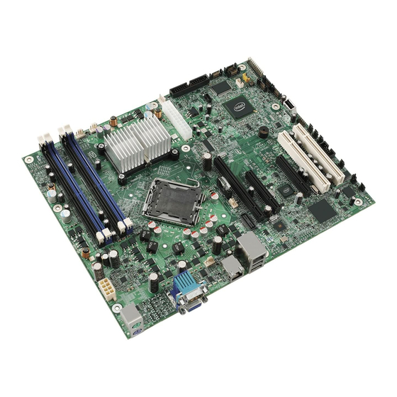
- Page 21 Intel® Server Boards S3200SH/S3210SH TPS Server Board Overview ® Figure 1. Intel Server Board S3210SHLX Diagram ® Table 1. Intel Server Board S3210SHLX Board SKU Layout Reference Description Description Description PCI-X (64bit/133MHz) Slot 1 Channel 2 DIMM Sockets SATA 1...
-
Page 22: Figure 1. Intel
Server Board Overview Intel® Server Boards S3200SH/S3210SH TPS The following figure shows the board layout of the LC board SKU. Each connector and major component is identified by letter (shown in Table 2). AF002304 ® Figure 2. Intel Server Board S3210SHLC Diagram ®... -
Page 23: Figure 2. Intel
Intel® Server Boards S3200SH/S3210SH TPS Server Board Overview The following figure shows the board layout of the Intel ® Server Boards S3200SHL/S3200SHV. Each connector and major component is identified by letter (shown in Table 3). AF002310 ® Figure 3. Intel Server Board S3200SH-L/S3200SH-V SKU Diagram ®... -
Page 24: Server Board Layout
Server Board Overview Intel® Server Boards S3200SH/S3210SH TPS Server Board Layout ® Figure 4. Intel Server Board S3210SHLC Revision 1.3... -
Page 25: Server Board Mechanical Drawings
Intel® Server Boards S3200SH/S3210SH TPS Server Board Overview 2.2.1 Server Board Mechanical Drawings ® Figure 5. Intel Server Board S3210SHLX – Hole and Component Positions Revision 1.3... -
Page 26: Figure 6. Intel ® Server Boards S3210Shlc/S3200Shl/S3200Shv - Hole And Component
Server Board Overview Intel® Server Boards S3200SH/S3210SH TPS ® Figure 6. Intel Server Boards S3210SHLC/S3200SHL/S3200SHV – Hole and Component Positions Revision 1.3... -
Page 27: Functional Architecture
Intel® Server Boards S3200SH/S3210SH TPS Functional Architecture Functional Architecture This chapter provides a high-level description of the functionality associated with the architectural blocks that make up the Intel ® Server Boards S3200SH/S3210SH. Revision 1.3... -
Page 28: Block Diagram
Functional Architecture Intel® Server Boards S3200SH/S3210SH TPS S3200SH/S3210SH LC/L/V SKU BLOCK DIAGRAM Intel® Xeon® Processors ITP/XDP 3000 sequence 1U Riser at Slot 6 PECI CK505 1333/1066/ Clock 800 FSB SYNTH DDR2 667/800 Intel® 3200/ 3210 MCH Thermal/ DDR2 667/800 X8 PCI-E... - Page 29 Intel® Server Boards S3200SH/S3210SH TPS Functional Architecture S3200SH/S3210SH SYSTEM LX SKU BLOCK DIAGRAM Intel® Xeon® Processors ITP/XDP 3000 Sequence 1U Riser at Slot 6 PECI CK505 1333/1066/ Clock 800 FSB SYNTH DDR2 667/800 Intel® 3200/ S3210 MCH Thermal/ DDR2 667/800...
-
Page 30: Processor Sub-System
3300 series The server board does not support the following processors: • All Intel 5XX series, 6XX series single core processors • All Intel 8XX series, 9XX series dual core processors The processors built on 65nm and 45nm process technology in the 775-land package utilize Flip-Chip Land Grid Array (FC-LGA4) package technology, and plug into a 775-land LGA ®... -
Page 31: Intel 3200/3210 Chipset
® Intel 3200/3210 Chipset ® The server board is designed around the Intel 3200/3210 Chipset. The chipset provides an integrated I/O bridge and memory controller, and a flexible I/O subsystem core (PCI Express*). The chipset consists of three primary components. - Page 32 An outbound request queue for subsequent forwarding to one of the PCI Express* or PCI buses ® The MCH also accepts inbound requests from the Intel ICH9R. The MCH is responsible for generating the appropriate controls to control data transfer to and from memory.
-
Page 33: Table 4. Segment F Connections
Intel® Server Boards S3200SH/S3210SH TPS Functional Architecture 3.2.1.1 Segment F PCIe* x8 The MCH PCIe* Lanes 0~7 provide a x8 PCIe* connection directly to the MCH. This resource can support x1, x4, and x 8 PCIe* add-in cards or cards through the I/O riser when using the riser slot for the L board SKU. -
Page 34: Pci-X* Hub (Pxh)
Functional Architecture Intel® Server Boards S3200SH/S3210SH TPS Please note the following memory population rules: • If dual channel operation is desired, channel A and channel B must be populated identically (i.e., same capacity) • Use DDR2 667/800 memory only •... -
Page 35: Intel ® Ich9R: I/O Controller Hub 9R
Intel® Server Boards S3200SH/S3210SH TPS Functional Architecture Table 6. Segment E Configuration IDs IDSEL Value Device PCI-X* Slot 1 (64bit/66-133MHz) (LX board SKU only) PCI-X* Slot 2 (64bit/66-133MHz) (LX board SKU only) 3.2.2.1.2 Segment E Arbitration PXH-V supports two PCI masters: two PCI-X* slots or one riser slot. All PCI masters must arbitrate for PCI access using resources supplied by the PXH-V. - Page 36 Functional Architecture Intel® Server Boards S3200SH/S3210SH TPS provides two modes of operation – a legacy mode using I/O space and an AHCI (Advanced Host Controller Interface) mode using memory space. 3.2.3.5 PCI Interface The ICH9 PCI interface provides a 33MHz, 3.3V, Revision 2.3 implementation. All PCI signals are 5V tolerant, except PME#.
- Page 37 QST. The Intel ® QST is controlled by the management engine (ME) residing in the MCH and requires SPI flash to host the Intel ® QST firmware. Additionally ICH9 integrates four fan speed TACH sensors and three fan speed controllers, PWMs.
-
Page 38: Table 8 Boot Bios Destination Selection
Functional Architecture Intel® Server Boards S3200SH/S3210SH TPS two SPI flash components using two separate chip select pins. Each component may be up to 16 MB and operate in SPI Fast Read Instructions and frequencies of 20 MHZ or 33 MHz. -
Page 39: Table 9: Spi Required Command Codes
JESD21-C, PRN03-NV1. The SPI Flash Memory device is the Atmel* AT26DF321 a 32-megabit, 2.7 to 3.6 volt serial interface FLASH memory, Intel part number D64145-001/D64145-002. The AT26DF321 supports the block erase command opcodes 20H and D8H providing respectively 4-Kbytes or 64-Kbytes block erase sizes. - Page 40 15 interrupts. It also supports processor system bus interrupts. 3.2.3.21 Advanced Programmable Interrupt Controller (APIC) ® Interrupt generation and notification to the processor is done by the APICs in the Intel ICH9R using messages on the front side bus. 3.2.3.22 Universal Serial Bus (USB) Controller ®...
-
Page 41: Memory Sub-System
3.2.3.23 Enhanced Power Management ® One of the embedded functions of the Intel ICH9R is a power management controller. This is used to implement ACPI-compliant power management features. The server board supports sleep states S1, S4, and S5. -
Page 42: Table 10. Memory Bank Labels And Dimm Population Order
Functional Architecture Intel® Server Boards S3200SH/S3210SH TPS The system is designed to populate any rank on either channel, including either degenerate single channel case. DIMM and memory configurations must adhere to the following: • DDR2 667/800, un-buffered, DDR2 DIMM modules •... -
Page 43: Figure 7. Memory Bank Label Definition
Intel® Server Boards S3200SH/S3210SH TPS Functional Architecture Figure 7. Memory Bank Label Definition Table 11. Characteristics of Dual/Single Channel Configuration with or without Dynamic Mode Throughput Level Configuration Characteristics Highest Dual channel with dynamic paging mode All DIMMs matched Dual channel without dynamic paging mode... -
Page 44: Memory Dimm Support
The board supports un-buffered (not registered) DDR2 667/800 ECC or non-ECC DIMMs operating at 667/800 MT/s. Only DIMMs tested and qualified by Intel or a designated memory test vendor are supported on this board. Note that all DIMMs are supported by design, but only fully qualified DIMMs will be supported on the board. -
Page 45: Table 13. Segment A Configuration Ids
ICH9R and one PCI bus master (NIC). All ® PCI masters must arbitrate for PCI access, using resources supplied by the Intel ICH9R. The host bridge PCI interface (ICH9R) arbitration lines REQx* and GNTx* are a special case in that they are internal to the host bridge. -
Page 46: Interrupt Routing
(INTA, INTB, INTC, INTD, INTE, INTF, INTG, INTH for ® PCI bus and PXIRQ0, PXIRQ1, PXIRQ2, PXIRQ3 for PCI-X bus) is connected. The Intel ICH9R I/O APIC exists on the I/O APIC bus with the processor. -
Page 47: Table 16. Interrupt Definitions
Functional Architecture 3.4.2.3 Legacy Interrupt Sources The table below recommends the logical interrupt mapping of interrupt sources on the board. ® The actual interrupt map is defined using configuration registers in the Intel ICH9R. Table 16. Interrupt Definitions ISA Interrupt Description INTR Processor interrupt. -
Page 48: Figure 8. Interrupt Routing Diagram
Functional Architecture Intel® Server Boards S3200SH/S3210SH TPS ICH9R IOAPIC 0 DMI INTERFACE IRQ0 IRQ1 IRQ2 IRQ3 IRQ4 IRQ5 IRQ6 IRQ7 IRQ8 IRQ9 ICH9R IRQ10 ICH9R IRQ11 8259PIC IRQ12 IRQ13 IRQ14 IRQ15 IRQ16 IRQ17 IRQ18 IRQ19 IRQ20 IRQ21 IRQ22 IRQ23 x8 PCIe* interface... -
Page 49: Figure 9. Intel Ich9R Interrupt Routing Diagram
Intel® Server Boards S3200SH/S3210SH TPS Functional Architecture Super I/O Timer Keyboard Cascade Serial Port2/ISA SERIRQ SERIRQ Serial Port1/ISA Floppy/ISA SCI/ISA Mouse/ISA Coprocessor Error P IDE/ISA Not Used PIRQA# PIRQB# ® Intel 82541PI NIC PIRQC# PIRQD# PIRQE# Slot 1 and 2 INTC... -
Page 50: Figure 10. Pxh-V Interrupt Routing Diagram
Functional Architecture Intel® Server Boards S3200SH/S3210SH TPS PCI-X* slot 6 INTD# PA IRQ0 PCI-X slot 6 INTA# PA IRQ1 PCI-X slot 6 INTC# PA IRQ2 PCI-X slot 6 INTB# PA IRQ3 PCI-X slot 5 INTD# PA IRQ4 PCI-X slot 5 INTA#... -
Page 51: Bmc Controller
Intel® Server Boards S3200SH/S3210SH TPS Functional Architecture BMC Controller The Integrated Baseboard Management Controller (Integrated BMC) is a highly integrated single-chip solution, integrating several devices typically found on servers. The Integrated BMC is mainly targeted at next generation servers, and provides a highly integrated server class product. -
Page 52: Pcie* To Pci-X* Bridge 6702Pxh (Pxh-V) (Lx Board Sku Only)
Graphics Subsystem PCIe* to PCI-X* Bridge 6702PXH (PXH-V) (LX Board SKU Only) The Intel 6702PXH 64-bit PCI Hub is a peripheral chip that performs PCI bridging functions between the PCI Express* interface and the PCI bus. The Intel 6702PXH 64-bit PCI Hub contains a single PCI bus interface that can be configured to operate in PCI (33 or 66 MHz) or PCI-X* Mode 1 (66, 100, or 133 MHz). -
Page 53: Clock Generator
Intel® Server Boards S3200SH/S3210SH TPS Functional Architecture The Intel 6702PXH 64-bit PCI Hub further support the new PCI Standard Hot-Plug Controller and Subsystem Specification, Revision 1.0. Each PCI interface contains an I/OxAPIC with 24 interrupts and a standard hot plug controller. -
Page 54: 3.10 Gige Phy
• IPMI support for server management 3.10 GigE PHY The Intel 82566 Gigabit Ethernet physical layer transceiver (PHY) is a single port device that supports the integrated ICH9 Media Access Controller (MAC) at 10 Mbps, 100 Mbps, or 1000 Mbps. -
Page 55: Table 17. Video Modes
Intel® Server Boards S3200SH/S3210SH TPS Functional Architecture 3.11.1.1 Video Modes Table 17. Video Modes 2D Mode Refresh Rate (Hz) 2D Video Mode Support 8 bpp 16 bpp 24 bpp 32 bpp 640x480 60, 72, 75, 90, 100 Supported Supported Supported... -
Page 56: 3.12 Replacing The Back-Up Battery
Functional Architecture Intel® Server Boards S3200SH/S3210SH TPS 3.12 Replacing the Back-Up Battery The lithium battery on the server board powers the RTC for up to ten years in the absence of power. When the battery starts to weaken, it loses voltage, and the server settings stored in CMOS RAM in the RTC (for example, the date and time) may be wrong. -
Page 57: System Bios
The string is formatted as follows: BoardFamilyID.OEMID.MajorRev.MinorRev.BuildID.BuildDateTime Where: • BoardFamilyID = String name for this board family. • OEMID = Three-character OEM ID. “86B” is used for Intel server boards. • MajorRev = Two decimal digits • MinorRev = Two decimal digits •... -
Page 58: Logo / Diagnostic Window
• BIOS ID. • Total memory detected (total size of all installed DIMMs) • Processor information (Intel branded string, speed, and number of physical processors identified) • Types of keyboards detected if plugged in (P/S2 and/or USB) • Types of mouse devices detected if plugged in (P/S 2 and/or USB) -
Page 59: Table 18. Bios Setup Page Layout
BIOS ID 4.3.1.2 Entering BIOS Setup BIOS Setup is started by pressing <F2> during boot time when the OEM or Intel logo is displayed. When Quiet Boot is disabled, there will be a message “press <F2> to enter setup” displayed on the diagnostics screen. -
Page 60: Table 19. Bios Setup: Keyboard Command Bar
Intel® Server Boards S3200SH/S3210SH TPS System BIOS The Keyboard Command Bar supports the following: Table 19. BIOS Setup: Keyboard Command Bar Option Description <Enter> Execute The <Enter> key is used to activate sub-menus when the selected feature is a sub-... -
Page 61: Server Platform Setup Screens
System BIOS Intel® Server Boards S3200SH/S3210SH TPS 4.3.1.4 Menu Selection Bar The Menu Selection Bar is located at the top of the screen. It displays the major menu selections available to the user. 4.3.2 Server Platform Setup Screens The sections below describe the screens available for the configuration of a server platform. In these sections, tables are used to describe the contents of each screen. -
Page 62: Figure 11. Setup Utility - Main Screen Display
Intel® Server Boards S3200SH/S3210SH TPS System BIOS Advance Main Security Server Management Boot Options Boot Manager Logged in as <Administrator or User> <Platform Identification String> Platform ID S3200X38.86B.xx.yy.zzzz BIOS Version <MM/DD/YYYY> Build Date Processor Intel® Xeon® CPU Core Frequency <Current Operating Frequency>... -
Page 63: Table 20. Setup Utility - Main Screen Fields
System BIOS Intel® Server Boards S3200SH/S3210SH TPS Table 20. Setup Utility — Main Screen Fields Setup Item Options Help Text Comments Logged in as Information only. Displays password level that setup is running in, Administrator or User. With no passwords set Administrator is the default mode. -
Page 64: Figure 12. Setup Utility - Advanced Screen Display
Intel® Server Boards S3200SH/S3210SH TPS System BIOS Setup Item Options Help Text Comments System Date [Day of week System Date has configurable MM/DD/YYYY] fields for Month, Day, and Year. Use [Enter] or [Tab] key to select the next field. Use [+] or [-] key to modify the selected field. -
Page 65: Table 21. Setup Utility - Advanced Screen Display Fields
System BIOS Intel® Server Boards S3200SH/S3210SH TPS Table 21. Setup Utility — Advanced Screen Display Fields Setup Item Options Help Text Comments View/Configure processor information and Processor Configuration settings. View/Configure memory information and Memory Configuration settings. View/Configure SATA Controller information SATA Controller Configuration and settings. -
Page 66: Figure 13. Setup Utility - Processor Configuration Screen Display
Intel® Server Boards S3200SH/S3210SH TPS System BIOS Advanced Processor Configuration Processor Family <String from Processor> Core Frequency <Current Processor Frequency> Maximum Frequency <Maximum Processor Speed Possible> System Bus Frequency <Current FSB Frequency> L2 Cache Size <Size of the cache> Processor Stepping <Stepping # of this processor>... - Page 67 System BIOS Intel® Server Boards S3200SH/S3210SH TPS Setup Item Options Help Text Comments Enhanced Intel® Enabled Enhanced Intel SpeedStep® Technology allows the system to dynamically adjust SpeedStep Technology Disabled processor voltage and core frequency, which can result in decreased average power consumption and decreased average heat production.
-
Page 68: Figure 14. Setup Utility - Memory Configuration Screen Display
Intel® Server Boards S3200SH/S3210SH TPS System BIOS Advanced Memory Configuration Total Memory <Total Physical Memory Installed in System> Effective Memory <Total Effective Memory> Current Configuration < Single Channel/Dual Channel > Current Memory Speed <Speed that installed memory is running at.>... -
Page 69: Figure 15. Setup Utility - Ata Controller Configuration Screen Display
System BIOS Intel® Server Boards S3200SH/S3210SH TPS Setup Item Options Help Text Comments Current Memory Information only. Displays speed the Speed memory is running at. DIMM_# Displays the state of each DIMM socket present on the board. Each DIMM socket... -
Page 70: Table 24. Setup Utility - Ata Controller Configuration Screen Fields
SATA drives When RAID is selected, no SATA [RAID] - SATA controller will be drive information is displayed. in RAID mode and the Intel® RAID for Serial ATA option ROM will execute. [IDE] – The SATA drives will be set to work as independent... -
Page 71: Figure 16. Setup Utility - Serial Port Configuration Screen Display
System BIOS Intel® Server Boards S3200SH/S3210SH TPS Advanced Serial Port Configuration Serial A Enable Enabled/Disabled Address 3F8h / 2F8h / 3E8h / 2E8h 3 or 4 Serial B Enable Enabled/Disabled Address 3F8h / 2F8h / 3E8h / 2E8h 3 or 4 Figure 16. -
Page 72: Figure 17. Setup Utility - Usb Controller Configuration Screen Display
Intel® Server Boards S3200SH/S3210SH TPS System BIOS Advanced USB Configuration Detected USB Devices <Total USB Devices in System> USB Controller Enabled / Disabled Legacy USB Support Enabled / Disabled / Auto USB Mass Storage Device Configuration Device Reset timeout 10 sec / 20 sec / 30 sec / 40 sec Storage Emulation <Mass storage devices one line/device>... -
Page 73: Table 26. Setup Utility - Usb Controller Configuration Screen Fields
System BIOS Intel® Server Boards S3200SH/S3210SH TPS Table 26. Setup Utility — USB Controller Configuration Screen Fields Setup Item Options Help Text Comments Detected USB Information only: shows number of Devices USB devices in system USB Controller [Enabled] - All onboard USB controllers will be turned on Enabled and accessible by the OS. -
Page 74: Figure 18. Setup Utility - Pci Configuration Screen Display
Intel® Server Boards S3200SH/S3210SH TPS System BIOS Advanced PCI Configuration Dual Monitor Video Enabled / Disabled Onboard NIC ROM Enabled / Disabled NIC 1 MAC Address <MAC #> NIC 2 MAC Address <MAC #> Figure 18. Setup Utility — PCI Configuration Screen Display Table 27. -
Page 75: Figure 19. Setup Utility - Security Configuration Screen Display
System BIOS Intel® Server Boards S3200SH/S3210SH TPS Main Advanced Security Server Management Boot Options Boot Manager Administrator Password Status <Installed/Not Installed> User Password Status <Installed/Not Installed> Set Administrator Password [1234abcd] Set User Password [1234abcd] Front Panel Lockout Enabled/Disabled Figure 19. Setup Utility — Security Configuration Screen Display Table 28. -
Page 76: Figure 20. Setup Utility - Server Management Configuration Screen Display
Intel® Server Boards S3200SH/S3210SH TPS System BIOS 4.3.2.4 Server Management Screen The Server Management screen provides fields to configure several server management features. It also provides an access point to the screens for configuring console redirection and displaying system information. - Page 77 Disabled before the timer expires, the BMC will reset the system and an error will be logged. Requires OS support or Intel Management Software. O/S Boot Watchdog If the OS watchdog timer is enabled, this is the system Power Off Timer Policy action taken if the watchdog timer expires.
-
Page 78: Figure 21. Setup Utility - Console Redirection Screen Display
Intel® Server Boards S3200SH/S3210SH TPS System BIOS Server Management Console Redirection Console Redirection Disabled / Serial A / Serial B Flow Control None / RTS/CTS Baud Rate 9.6k / 19.2k / 38.4k / 57.6k / 115.2k Terminal Type PC-ANSI / VT100 / VT100+ / VT-UTF8... -
Page 79: Figure 22. Setup Utility - Server Management System Information Screen Display
System BIOS Intel® Server Boards S3200SH/S3210SH TPS 4.3.2.5 Server Management System Information Screen The Server Management System Information screen provides a place to see part numbers, serial numbers, and firmware revisions. To access this screen from the Main screen, select Server Management. Select the System Information option from the Server Management screen. -
Page 80: Figure 23. Setup Utility - Boot Options Screen Display
Intel® Server Boards S3200SH/S3210SH TPS System BIOS 4.3.2.6 Boot Options Screen The Boot Options screen displays any bootable media encountered during POST, and allows the user to configure desired boot device. To access this screen from the Main screen, select Boot Options. -
Page 81: Figure 24. Setup Utility - Hard Disk Order Screen Display
System BIOS Intel® Server Boards S3200SH/S3210SH TPS Setup Item Options Help Text Comments Hard Disk Order Set hard disk boot order by selecting Appears when more than 1 the boot option for this position. hard disk drive is in the system. -
Page 82: Figure 25. Setup Utility - Cdrom Order Screen Display
Intel® Server Boards S3200SH/S3210SH TPS System BIOS 4.3.2.6.2 CDROM Order Screen The CDROM Order screen provides a way to control the CDROM devices. To access this screen from the Main screen, select Boot Options | CDROM Order. Boot Options CDROM <Available CDROM devices>... -
Page 83: Figure 27. Setup Utility - Network Device Order Screen Display
System BIOS Intel® Server Boards S3200SH/S3210SH TPS Table 35. Setup Utility — Floppy Order Fields Setup Item Options Help Text Comments Floppy Disk #1 Available floppy Set floppy disk boot order by selecting the disk boot option for this position. -
Page 84: Figure 28. Setup Utility - Bev Device Order Screen Display
Intel® Server Boards S3200SH/S3210SH TPS System BIOS 4.3.2.6.5 BEV Device Order Screen The BEV Device Order screen provides a way to control the BEV bootable devices. To access this screen from the Main screen, select Boot Options | BEV Device Order. -
Page 85: Figure 29. Setup Utility - Boot Manager Screen Display
System BIOS Intel® Server Boards S3200SH/S3210SH TPS 4.3.2.7 Boot Manager Screen The Boot Manager screen displays a list of devices available to boot from, and allows the user to select a boot device for this boot. To access this screen from the Main screen, select Boot Manager. -
Page 86: Figure 31. Setup Utility - Exit Screen Display
Intel® Server Boards S3200SH/S3210SH TPS System BIOS Table 39. Setup Utility — Error Manager Screen Fields Setup Item Options Help Text Comments Displays System Errors Information only. Displays errors that occurred during this POST. 4.3.2.9 Exit Screen The Exit screen allows the user to choose to save or discard the configuration changes made on the other screens. - Page 87 Intel will publish a third party chassis fan speed control white paper to guide customers on how to edit the master.cfg file to have fan speed control functions for the third party chassis. Without...
-
Page 88: Loading Bios Defaults
Intel® Server Boards S3200SH/S3210SH TPS System BIOS Loading BIOS Defaults Different mechanisms exist for resetting the system configuration to the default values. When a request to reset the system configuration is detected, the BIOS loads the default system configuration values during the next POST. The request to reset the system to the defaults can be sent in the following ways: •... -
Page 89: Intel ® Matrix Storage Manager
Intel Embedded Server RAID Technology II Support ® The onboard storage capability of this server board includes support for Intel Embedded Server RAID Technology, which provides three standard software RAID levels: data striping (RAID Level 0), data mirroring (RAID Level 1), and data striping with mirroring (RAID Level 10). -
Page 90: Error Reporting And Handling
Error Reporting and Handling Intel® Server Boards S3200SH/S3210SH TPS Error Reporting and Handling This chapter defines following error handling features: • Error Handling and Logging • Error Messages and Beep Codes Error Handling and Logging This section defines how errors are handled by the system BIOS. In addition, error-logging techniques are described and beep codes for errors are defined. -
Page 91: Error Logging Via Smi Handler
Intel® Server Boards S3200SH/S3210SH TPS Error Reporting and Handling Code. PCI PERR error PERR error happens on PCI bus POST / Runtime PCI SERR error SERR error happens on PCI bus POST / Runtime 5.1.2 Error Logging via SMI Handler The SMI handler is used to handle and log system level events. -
Page 92: Table 42. Smbios Type 15 Event Log Record Format
Error Reporting and Handling Intel® Server Boards S3200SH/S3210SH TPS Table 42. SMBIOS Type 15 Event Log record format Offset Name Length Description EventType Byte Specifies the “Type” of event noted in an event-log entry as defined in table. Length Byte Specifies the byte length of the event record, including the record’s Type and... -
Page 93: Error Messages And Error Codes
For information on the EFI_STATUS_CODE_TYPE and EFI_STATUS_CODE_VALUE definitions, please refer to “Intel Platform Innovation Framework for EFI Status Codes Specification”, version 0.92. The errors will also be displayed on the BIOS Setup screen in Server Management / View... -
Page 94: Post Code Checkpoints
Error Reporting and Handling Intel® Server Boards S3200SH/S3210SH TPS • Red bits = 1010b = Ah • Green bits = 1100b = Ch Since the red bits correspond to the upper nibble and the green bits correspond to the lower nibble, the two are concatenated to be ACh. - Page 95 Intel® Server Boards S3200SH/S3210SH TPS Error Reporting and Handling Diagnostic LED Decoder Description G=Green, R=Red, A=Amber Checkpoint 0x25h Configuring memory parameters in the memory controller 0x26h Optimizing memory controller settings 0x27h Initializing memory, such as ECC init 0x28h Testing memory...
- Page 96 Error Reporting and Handling Intel® Server Boards S3200SH/S3210SH TPS Diagnostic LED Decoder Description G=Green, R=Red, A=Amber Checkpoint Fixed Media 0xB0h Resetting fixed media device 0xB1h Disabling fixed media device 0xB2h Detecting presence of a fixed media device (IDE hard drive detection, etc.)
-
Page 97: Post Error Messages And Handling
Intel® Server Boards S3200SH/S3210SH TPS Error Reporting and Handling Diagnostic LED Decoder Description G=Green, R=Red, A=Amber Checkpoint 0xEAh Flash Update 0xEEh Calling Int 19; one beep unless silent boot is enabled. 0xEFh Reserved for DXE Drivers use Runtime Phase / EFI Operating System Boot... -
Page 98: Post Error Beep Codes
Error Reporting and Handling Intel® Server Boards S3200SH/S3210SH TPS Table 46. POST Error Messages and Handling Error Code Error Message Response Log Error CMOS date / time not set Pause Configuration cleared by jumper Pause Configuration default loaded Pause Password check failed... -
Page 99: Connectors And Jumper Blocks
Connectors and Jumper Blocks Intel® Server Boards S3200SH/S3210SH TPS Connectors and Jumper Blocks Power Connectors 6.1.1 Main Power Connector The following table defines the pin-out of the main power connector. Table 48. Power Connector Pin-out (J4G1) Signal 18 AWG Color... -
Page 100: Intel ® Riser Card For L Sku
Server Board S3200SH-L has a PCIe* x16 to PCIe* x16 riser card. ® This riser card is designed to be populated with PCIe* x16 slot on the Intel Server Board S3200SH-L. The physical layout to the PCIe* x16 slot on the riser card is PCIe* x8. -
Page 101: I/O Connectors
Connectors and Jumper Blocks Intel® Server Boards S3200SH/S3210SH TPS I/O Connectors 6.5.1 VGA Connector The following table details the pin-out of the VGA connector. This connector is stacked with the COM1 connector. Table 52. VGA Connector Pin-out (J8B1) Signal Name... -
Page 102: Sata Connectors
Intel® Server Boards S3200SH/S3210SH TPS Connectors and Jumper Blocks ® Table 54. NIC1- Intel 82566E (10/100/1000) Connector Pin-out (J6B1) Signal Name Signal Name P2V5_NIC1 P3V3_AUX NIC1_MDI0_DP NIC1_LINK_0_N NIC1_MDI0_DN NIC1_LINK_2_N NIC1_MDI1_DP NIC1_MDI1_DN NIC1_MDI2_DP NIC1_MDI2_DN NIC1_MDI3_DP NIC1_MDI3_DN NIC1_LINK_1_N 6.5.3 SATA Connectors The pin-out for the four SATA connectors is listed below. -
Page 103: Serial Port Connectors
Connectors and Jumper Blocks Intel® Server Boards S3200SH/S3210SH TPS Signal Name Signal Name FDR0# FDMTR1# Unused FDDIR FDSTEP# FDWDATA# FDWGATE# FDTRK0# Unused FLWP# FRDATA# FHDSEL# FDSKCHG# 6.5.5 Serial Port Connectors One serial port is provided on the server board. A standard, external DB9 serial connector is located on the back edge of the server board to supply a serial interface. -
Page 104: Keyboard And Mouse Connector
Intel® Server Boards S3200SH/S3210SH TPS Connectors and Jumper Blocks 6.5.6 Keyboard and Mouse Connector Two PS/2 ports are provided for use by a keyboard and a mouse. The following table details the pin-out of the PS/2 connectors. Table 58. Keyboard and Mouse PS/2 Connectors Pin-out (J9A1) -
Page 105: Fan Headers
Connectors and Jumper Blocks Intel® Server Boards S3200SH/S3210SH TPS A header on the server board provides an option to support two additional USB connectors. The pin-out of the header is detailed in the following table. Table 60. Optional USB Connection Header Pin-out (J1G1) -
Page 106: Chassis Intrusion Header
6.7.5 HSBP ® There is a 4-pin HSBP connector jumper. This jumper is reserved for connecting to the Intel Entry Server Chassis SC5299-E hot-swap backplane. 6.7.6 SATA SGPIO There is a 4-pin SATA SGPIO connector jumper. This jumper is reserved for connecting to the ®... -
Page 107: Jumper Blocks
Connectors and Jumper Blocks Intel® Server Boards S3200SH/S3210SH TPS Jumper Blocks This section describes the configuration jumper options on the server board. Locatio Locatio Name n on Function Definition n on LX LC/L/V Clear CMOS 1-2: Normal CMOS Clear J1E3... -
Page 108: Absolute Maximum Ratings
Intel® Server Boards S3200SH/S3210SH TPS Absolute Maximum Ratings Absolute Maximum Ratings Operating the server board at conditions beyond those shown in the following table may cause permanent damage to the system. The table is provided for stress testing purposes only. -
Page 109: Design And Environmental Specifications
Design and Environmental Specifications Intel® Server Boards S3200SH/S3210SH TPS Design and Environmental Specifications Power Budget The following table shows the power consumed on each supply line for the server board that is configured with one processor (128W max). This configuration includes four 1 GB DDR2 DIMMs stacked burst at 70% max. -
Page 110: Power Supply Specifications
Intel® Server Boards S3200SH/S3210SH TPS Design and Environmental Specifications Power Supply Specifications This section provides power supply design guidelines for the server board, including voltage and current specifications, and power supply on/off sequencing characteristics. Table 67. Server Board Power Supply Voltage Specification... -
Page 111: Figure 35. Output Voltage Timing
Design and Environmental Specifications Intel® Server Boards S3200SH/S3210SH TPS The 5VSB output voltage rise time will be from 1.0ms to 25.0ms Vout Vout Tvout_off Tvout_rise Tvout_on Figure 35. Output Voltage Timing Revision 1.3... -
Page 112: Figure 36. Turn On/Off Timing (Power Supply Signals)
Intel® Server Boards S3200SH/S3210SH TPS Design and Environmental Specifications Table 69. Turn On/Off Timing Item Description Units Tsb_on_delay Delay from AC being applied to 5VSB being within msec 1500 regulation. T ac_on_delay Delay from AC being applied to all output voltages being... -
Page 113: Dynamic Loading
Design and Environmental Specifications Intel® Server Boards S3200SH/S3210SH TPS 8.2.2 Dynamic Loading The output voltages shall remain within limits specified for the step loading and capacitive loading specified in the table below. The load transient repetition rate shall be tested between 50Hz and 5kHz at duty cycles ranging from 10%-90%. -
Page 114: Ac Line Fast Transient (Eft) Specification
Intel® Server Boards S3200SH/S3210SH TPS Design and Environmental Specifications Table 72. AC Line Surge Transient Performance AC Line Surge Duration Surge Operating AC Voltage Line Performance Criteria Frequency Continuous Nominal AC Voltages 50/60Hz No loss of function or performance. 0 to ½ AC... -
Page 115: Product Emc Compliance - Class A Compliance
Design and Environmental Specifications Intel® Server Boards S3200SH/S3210SH TPS 8.3.2 Product EMC Compliance – Class A Compliance Note: Legally the product is required to comply with Class A emission requirements as it is intended for a commercial type market place. -
Page 116: Rohs
8.3.4 RoHS Intel has a system in place to restrict the use of banned substances in accordance with the European Directive 2002/95/EC. Compliance is based on declaration that materials banned in the RoHS Directive are either (1) below all applicable substance threshold limits or (2) an approved/pending RoHS exemption applies. -
Page 117: Product Regulatory Compliance Markings
Design and Environmental Specifications Intel® Server Boards S3200SH/S3210SH TPS 8.3.5 Product Regulatory Compliance Markings This product is marked with the following Product Certification Markings: Table 73. Product Certification Markings Regulatory Compliance Region Marking UL Mark USA/Canada E139761 CE Mark Europe... -
Page 118: Electromagnetic Compatibility Notices
Intel® Server Boards S3200SH/S3210SH TPS Design and Environmental Specifications Electromagnetic Compatibility Notices 8.4.1 FCC (USA) This device complies with Part 15 of the FCC Rules. Operation is subject to the following two conditions: (1) this device may not cause harmful interference, and (2) this device must accept any interference received, including interference that may cause undesired operation. -
Page 119: Ices-003 (Canada)
Design and Environmental Specifications Intel® Server Boards S3200SH/S3210SH TPS 8.4.2 ICES-003 (Canada) Cet appareil numérique respecte les limites bruits radioélectriques applicables aux appareils numériques de Classe B prescrites dans la norme sur le matériel brouilleur: “Appareils Numériques”, NMB-003 édictée par le Ministre Canadian des Communications. -
Page 120: Korean Compliance (Rrl)
English translation of the notice above: Type of Equipment (Model Name): On License and Product Certification No.: On RRL certificate. Obtain certificate from local Intel representative Name of Certification Recipient: Intel Corporation Date of Manufacturer: Refer to date code on product... -
Page 121: Mechanical Specifications
Design and Environmental Specifications Intel® Server Boards S3200SH/S3210SH TPS Mechanical Specifications ® The following figure shows the Intel Server Board S3200SH mechanical drawing. This drawing will be updated in a future revision of this document. ® Figure 37. Intel Server Board S3200SH Mechanical Drawing (TBD) -
Page 122: Figure 38. Pedestal Mount I/O Shield Mechanical Drawing For The Intel ® Server Board S3200Sh- V
Server Board S3200SH-L and the Intel Server Board S3200SH-LX/LC share same I/O ® shield, and Intel Server Board S3200SH-V employs a separate I/O shield. ® Figure 38. Pedestal Mount I/O Shield Mechanical Drawing for the Intel Server Board S3200SH-V Revision 1.3... -
Page 123: Figure 39. Pedestal Mount I/O Shield Mechanical Drawing For Intel Server Boards S3200Sh-L
Design and Environmental Specifications Intel® Server Boards S3200SH/S3210SH TPS ® Figure 39. Pedestal Mount I/O Shield Mechanical Drawing for Intel Server Boards S3200SH-L / S3210SH-LX Revision 1.3... -
Page 124: Hardware Monitoring
Intel® Server Boards S3200SH/S3210SH TPS Hardware Monitoring Hardware Monitoring Chassis Intrusion The server board supports a chassis security feature that detects if the chassis cover is removed. For the chassis intrusion circuit to function, the chassis’ power supply must be connected to AC power. -
Page 125: Glossary
Intel® Server Boards S3200SH/S3210SH TPS Glossary Glossary This appendix contains important terms used in the preceding chapters. For ease of use, numeric entries are listed first (e.g., “82460GX”) with alpha entries following (e.g., “AGP 4x”). Acronyms are then entered in their respective place, with non-acronyms following. - Page 126 Intel® Server Boards S3200SH/S3210SH TPS Glossary Term Definition Least Significant Bit 1024 KB Multi-Bit Error milliseconds Most Significant Bit MTBF Mean Time Between Failures multiplexor Network Interface Card Non-maskable Interrupt Original equipment manufacturer Unit of electrical resistance PBGA Pin Ball Grid Array...
- Page 127 Intel® Server Boards S3200SH/S3210SH TPS Glossary Term Definition Video Graphic Adapter Voltage Identification Voltage Regulator Module Word 16-bit quantity Zero Channel RAID Revision 1.3...
-
Page 128: Reference Documents
Reference Documents Refer to the following documents for additional information: ® Intel S3200 Server Board Family Datasheet ® Intel 3200 Series Chipset Memory Controller Hub Datasheet. ® Intel ICH9 I/O Controller Hub Datasheet. Revision 1.3...
Need help?
Do you have a question about the S3210SHLX - Entry Server Board Motherboard and is the answer not in the manual?
Questions and answers