
Related Manuals for Intel S1200BTS


Summary of Contents for Intel S1200BTS
- Page 1 ® Intel Server Board S1200BT Technical Product Specification Intel order number G13326-003 Revision 1.0 March, 2011 Enterprise Platforms and Services Division...
-
Page 2: Revision History
Revision Number Modifications July 2010 Initial release. November 2010 Updated the hardware info and SE SKU. January 2011 Updated S1200BTS info and BIOS setup page. January 2011 Updated S1200BT video mode. March 2011 Corrected typos. Revision 1.0 Intel order number G13326-003... - Page 3 ® Information in this document is provided in connection with Intel products. No license, express or implied, by estoppel or otherwise, to any intellectual property rights is granted by this document. Except as provided in Intel‘s ® ® Terms and Conditions of Sale for such products, Intel...
-
Page 4: Table Of Contents
Table of Contents Intel® Server Board S1200BT TPS Table of Contents 1. Introduction ........................1 Chapter Outline ...................... 1 Server Board Use Disclaimer ................. 1 2. Overview ..........................2 ® Intel Server Board S1200BT Feature Set ............. 2 Server Board Layout ....................4 2.2.1... - Page 5 ® 3.7.1 Intel Server Board S1200BTL ................28 ® 3.7.2 Video for Intel Server Board S1200BTS ............. 29 Network Interface Controller (NIC) ............... 29 3.8.1 Gigabit Ethernet Controller 82574L ..............29 3.8.2 Gigabit Ethernet PHY 82579 ................29 3.8.3 MAC Address Definition ..................30 ®...
- Page 6 Table of Contents Intel® Server Board S1200BT TPS ® 5. Server Management Capability for Intel Server Board S1200BTS....... 46 Supper I/O......................46 5.1.1 Key Features of supper I/O .................. 46 6. BIOS User Interface ......................47 BIOS POST Initialization ..................47 6.1.1...
- Page 7 CMOS Clear and Password Reset Usage Procedure ......... 105 8.1.1 Clearing the CMOS .................... 106 8.1.2 Clearing the Password ..................106 ® Integrated BMC Force Update Procedure (Only for The Intel Server Board S1200BTL) .......................... 107 ME Force Update Jumper .................. 107 BIOS Recovery Jumper ..................108 ®...
- Page 8 Figure 28. System Information Screen (S1200BTL) ..............78 Figure 29.System Information Screen (S1200BTS) ..............79 Figure 30. BMC LAN Configuration Screen (S1200BTL)............80 Figure 31. Hardware Monitor Screen, Auto Fan Control (S1200BTS) ........81 Figure 32. Hardware Monitor Screen, Manual Fan Control (S1200BTS) ........81 viii Revision 1.0...
- Page 9 Figure 45. Exit Screen ......................89 Figure 46. Jumper Blocks (J4A2, J1F1, J1F3, J1F2, and J1E2) on S1200BTL ....... 104 Figure 47. Jumper Blocks (J2G1, J1G1, J1H3, and J2J1) on S1200BTS ....... 105 Figure 48. POST Code Diagnostic LED Location ..............110 Figure 49.
- Page 10 Table 6. UDIMM Maximum configuration .................. 20 Table 7. Optional RMM4 Advanced Management Board Features ..........27 Table 8. Serial B Header (J1B2 on S1200BTL or J8A1 on S1200BTS) Pin-out ......27 Table 9. Video Modes ....................... 28 Table 10. Dual Video Modes ..................... 29 Table 11.
- Page 11 Table 41. SSI 4-pin Fan Header Pin-out ................. 103 Table 42. Server Board Jumpers (J1F1, J1F2, J1F3, J1E2, and J4A2) on S1200BTL .... 104 Table 43. Server Board Jumpers (J2G1, J1G1, J1H3, and J2J1) on S1200BTS ....105 Table 44. Front Panel LED Behavior Summary ............... 109 Table 45.
-
Page 12: This Page Is Intentionally Left Blank
List of Tables Intel® Server Board S1200BT TPS <This page is intentionally left blank.> Revision 1.0 Intel order number G13326-003... -
Page 13: Introduction
Glossary Reference Documents Server Board Use Disclaimer Intel Corporation server boards contain a number of high-density VLSI and power delivery ® components that need adequate airflow to cool. Intel ensures through its own chassis ® development and testing that when Intel server building blocks are used together, the fully integrated system meets the intended thermal requirements of these components. -
Page 14: Overview
Overview Intel® Server Board S1200BT TPS Overview ® The Intel Server Board S1200BT is a monolithic printed circuit board (PCB) with features designed to support entry-level severs. It has two board SKUs, namely S1200BTL and S1200BTS. ® Intel Server Board S1200BT Feature Set ®... - Page 15 SATA connectors provides SATA and 10 and optional RAID 5 support RAID 0, 1, and 10 and optional RAID ® ® provided by the Intel RAID Activation 5 support provided by the Intel Key AXXRAKSW5 RAID Activation Key AXXRAKSW5. ® ® ...
-
Page 16: Server Board Layout
Overview Intel® Server Board S1200BT TPS Server Board Layout ® Figure 1. Intel Server Board S1200BTL Picture Revision 1.0 Intel order number G13326-003... -
Page 17: Server Board Connector And Component Layout
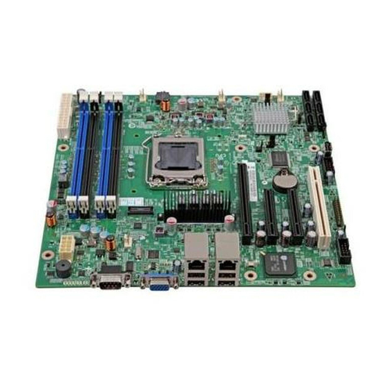
Intel® Server Board S1200BT TPS Overview ® Figure 2. Intel Server Board S1200BTS Picture 2.2.1 Server Board Connector and Component Layout The following figure shows the board layout of the server board. Each connector and major component is identified by a number or letter, and Table 2 provides the description. -
Page 18: Table 2. Major Board Components
Overview Intel® Server Board S1200BT TPS ® Figure 3. Intel Server Board S1200BTL Layout Table 2. Major Board Components Description Description Slot 1, 32 Mbit/33 MHz PCI System FAN2 and System FAN3 Connector CPU connector Slot 3/4, PCI Express* Gen2 x4 (x8 connector) -
Page 19: Figure 4. Intel Server Board S1200Bts Layout
Intel® Server Board S1200BT TPS Overview Description Description CPU Power Connector HDD LED SYS_FAN_4 Internal USB Connector RMM4 Dedicated NIC connector CMOS battery Four DIMM Slots Four 3Gb/s SATA ports P/S AUX Two 6Gb/s SATA ports MAIN POWER Smart module ®... -
Page 20: Intel ® Server Board S1200Btl Mechanical Drawings
Overview Intel® Server Board S1200BT TPS Description Description SATA_KEY CPU Fan connector Slot 7, PCI Express* Gen2 x8 (x16 connector) Chassis Intrusion Ethernet and Dual USB COMBO SATA_SGPIO Ethernet and Dual USB COMBO SYS_FAN_3 Video port Six 3Gb/s SATA ports... -
Page 21: Figure 5. Intel Server Board S1200Btl - Hole And Component Positions
Intel® Server Board S1200BT TPS Overview ® Server Board S1200BTL – Hole and Component Positions Figure 5. Intel Revision 1.0 Intel order number G13326-003... -
Page 22: Figure 6. Intel Server Board S1200Btl - Major Connector Pin Location (1 Of 2)
Overview Intel® Server Board S1200BT TPS ® Server Board S1200BTL – Major Connector Pin Location (1 of 2) Figure 6. Intel Revision 1.0 Intel order number G13326-003... -
Page 23: Figure 7. Intel Server Board S1200Btl - Major Connector Pin Location (2 Of 2)
Intel® Server Board S1200BT TPS Overview ® Server Board S1200BTL – Major Connector Pin Location (2 of 2) Figure 7. Intel Revision 1.0 Intel order number G13326-003... -
Page 24: Figure 8. Intel Server Board S1200Btl - Primary Side Keepout Zone
Overview Intel® Server Board S1200BT TPS ® Server Board S1200BTL – Primary Side Keepout Zone Figure 8. Intel Revision 1.0 Intel order number G13326-003... -
Page 25: Figure 9. Intel Server Board S1200Btl - Secondary Side Keepout Zone
Intel® Server Board S1200BT TPS Overview ® Server Board S1200BTL – Secondary Side Keepout Zone Figure 9. Intel Revision 1.0 Intel order number G13326-003... -
Page 26: Server Board Rear I/O Layout
Overview Intel® Server Board S1200BT TPS 2.2.3 Server Board Rear I/O Layout The following figure shows the layout of the rear I/O components for the server board. Serial Port A NIC Port 1 (1 Gb) and Dual USB Port Connector... -
Page 27: Functional Architecture
The architecture and design of the Intel Server Board S1200BT is based on the Intel C202 ® ® Chipset. The chipset is designed for systems based on the Intel Xeon processor in the FC- LGA 1155 socket package. ® ®... -
Page 28: Processor Sub-System
COM Port Internal USB Type-A Rear I/O USB Header x2 Header Ports x2 ® Figure 12. Intel Server Board S1200BTS Functional Block Diagram Processor Sub-System ® The Intel Server Board S1200BT supports the following processor: ® ® Intel Xeon Processor E3-1200 Series. -
Page 29: Intel ® Core™ Processor I3-2100 Series
Intel® Server Board S1200BT TPS Functional Architecture ® ® The server board does not support previous generations of the Intel Xeon processors. The list of supported processors may be found at http://serverconfigurator.intel.com. Note: The workstation processor is not supported in this platform. -
Page 30: Memory Supported
Functional Architecture Intel® Server Board S1200BT TPS The memory channels are named as ―Channel A‖ and ―Channel B‖. The memory slots are named as ―Slot1‖ and ―Slot2‖ on each channel. Slot1will be the farthest from the processor socket. -
Page 31: Memory Map And Population Rules
® o When both channels are populated, but with different numbers of DIMMs, Intel Flex Memory Technology divides the installed memory into two zones, using interleaved Dual Channel Symmetric mode as far as the highest address on the less-populated channel, then using uninterleaved Dual Channel Asymmetric mode for the remaining memory on the more-populated channel. -
Page 32: Table 4. Memory Configuration Table
Functional Architecture Intel® Server Board S1200BT TPS The maximum memory bandwidth is 10.6 GB/s in Single-Channel mode or 21 GB/s in Dual-Channel Symmetric mode, assuming DDR3 running at 1333 MT/s. 3.2.3.1 Memory Configuration Table Table 4. Memory Configuration Table... -
Page 33: Publishing System Memory
Xeon Processor E3-1200 series ® ® Core™ Processor i3-2100 in a UP server platform. The role of the PCH in the Intel or Intel Server Board S1200BT is to manage the flow of information between its eleven interfaces, described below: ... -
Page 34: I/O Sub-System
Functional Architecture Intel® Server Board S1200BT TPS USB host interface SMBus Host interface Serial Peripheral interface LAN interface ACPI interface I/O Sub-system ® Intel C200 Series PCH provides extensive I/O support. 3.4.1 Digital Media Interface (DMI) Direct Media Interface (DMI) is the chip-to-chip connection between the processor and C202 chipset. -
Page 35: Low Pin Count (Lpc) Interface
Two internal 2x5 headers (J1E1 and J1D1) are provided, each supporting two optional USB 2.0 ports. ® One port on internal smart module connector (J1J2) on Intel Server Board S1200BTL. 3.4.5.1 Native USB Support During the power-on self test (POST), the BIOS initializes and configures the USB subsystem. -
Page 36: Optional Intel Sas Raid Module
Integrated Baseboard Management Controller ® The Intel Server Board S1200BTL has the highly integrated single-chip baseboard ® management controller based on ServerEngines* Pilot III, but Intel Server Board S1200BTS does not have the integrated baseboard management control. ® This Intel Integrated BMC contains the following integrated subsystems and features. - Page 37 Intel® Server Board S1200BT TPS Functional Architecture JTAG Master Eight I2C interfaces with master-slave and SMBus timeout support. All interfaces are SMBus 2.0 compliant. Parallel general-purpose I/O Ports (16 direct, 32 shared) Serial general-purpose I/O Ports (80 in and 80 out) ...
-
Page 38: Integrated Bmc Embedded Lan Channel
Functional Architecture Intel® Server Board S1200BT TPS Figure 13. Integrated BMC Hardware 3.6.1 Integrated BMC Embedded LAN Channel The Integrated BMC hardware includes two dedicated 1000M network interfaces. Interface 1: This interface is available from either of the available NIC ports in system that can be shared with the host. -
Page 39: Optional Rmm4 Advanced Management Board
The Serial B port is an optional port accessed through a 9-pin internal DH-10 header (J1B1 on S1200BTL; J8A1 on S1200BTS). You can use a standard DH-10 to DB9 cable to direct serial A port to the rear of a chassis. The serial B interface follows the standard RS-232 pin-out as defined in the following table: Table 8. -
Page 40: Keyboard And Mouse Support
Functional Architecture Intel® Server Board S1200BT TPS 3.6.5 Keyboard and Mouse Support The server board does not support PS/2 interface keyboards and mouse. However, the system BIOS recognizes USB specification-compliant keyboard and mouse. 3.6.6 Wake-up Control The super I/O contains functionality that allows various events to power on and power off the system. -
Page 41: Video For Intel ® Server Board S1200Bts
Server Board S1200BT supports two network interfaces, One is provided from the ® ® onboard Intel 82574L GbE PCI Express network controller; the other is the onboard Intel 82579 Gigabit Network controller. 3.8.1 Gigabit Ethernet Controller 82574L The 82574 family (82574L and 82574IT) are single, compact, low-power components that offer a fully-integrated Gigabit Ethernet Media Access Control (MAC) and Physical Layer (PHY) port. -
Page 42: Mac Address Definition
Remote Management Module 4 dedicated NIC MAC address – Assigned the NIC Intel 1 MAC address +3 ® Each Intel Server Board S1200BTS has the following two MAC addresses assigned to it at the ® Intel factory: NIC 1 MAC address NIC 2 MAC address –... -
Page 43: Tpm (Trusted Platform Module)
Intel® Server Board S1200BT TPS Functional Architecture 3.11 TPM (Trusted Platform Module) There is one TPM module connector. The detail information is listed below: Embedded TPM 1.2 firmware 33-MHz Low Pin Count (LPC) interface V1.1 Compliant with TCG PC client specific TPM ... -
Page 44: Platform Management
Intel® Server Board S1200BT TPS Platform Management ® This chapter is only for The Intel Server Board S1200BTL. The platform management subsystem is based on the Integrated BMC features of the ServerEngines* Pilot III. The onboard platform management subsystem consists of communication buses, sensors, system BIOS, and server management firmware. -
Page 45: 4.1 Feature Support
Intel® Server Board S1200BT TPS Platform Management 4.1 Feature Support 4.1.1 IPMI 2.0 Features Baseboard management controller (BMC). IPMI Watchdog timer Messaging support, including command bridging and user/session support Chassis device functionality, including power/reset control and BIOS boot flags support ... -
Page 46: New Manageability Features
Platform Management Intel® Server Board S1200BT TPS Signal testing support: The BMC provides test commands for setting and getting platform signal states. The BMC generates diagnostic beep codes for fault conditions. System GUID storage and retrieval ... -
Page 47: Basic And Optional Advanced Management Features
Intelligent Power Node Manager Support*** SMASH CLP * Basic management features provided by Integrated BMC ® **Advanced management features available with optional Intel Remote Management Module 4 ® ***Intel Intelligent Power Node Manager Support requires PMBus-compliant power supply Revision 1.0... -
Page 48: Enabling Advanced Management Features
Basic and Advanced features. An optional add-in card Intel RMM4-lite is used as the activation ® mechanism. When the Integrated BMC firmware initializes, it attempts to access the Intel ® RMM4-lite. If the attempt to access Intel RMM4-lite is successful, then the Integrated BMC activates the advanced features. - Page 49 Intel® Server Board S1200BT TPS Platform Management The Remote Console window is a Java Applet that establishes TCP connections to the Integrated BMC. The protocol that is run over these connections is a unique KVM protocol and not HTTP or HTTPS. This protocol uses ports #7578 for KVM, #5120 for CDROM media redirection, and #5123 for Floppy/USB media redirection (both supporting encryption).
-
Page 50: Media Redirection
Platform Management Intel® Server Board S1200BT TPS 4.2.3 Media Redirection The embedded web server provides a Java applet to enable remote media redirection. This may be used in conjunction with the remote KVM feature, or as a standalone applet. The media redirection feature is intended to allow system administrators or users to mount a remote IDE or USB CD-ROM, floppy drive, or a USB flash disk as a remote device to the server. -
Page 51: Embedded Web Server
Intel® Server Board S1200BT TPS Platform Management 4.2.3.1 Availability The default inactivity timeout is 30 minutes and is not user-configurable. Media redirection sessions persist across system reset but not across an AC power loss or BMC reset. 4.2.3.2 Network Port Usage The KVM and media redirection features use the following ports: ... -
Page 52: Embedded Platform Debug
The files are compressed, encrypted, and password protected. The file is not meant ® to be viewable by the end user but rather to provide additional debugging capability to an Intel support engineer. Revision 1.0... -
Page 53: Data Center Management Interface (Dcmi)
Intel® Server Board S1200BT TPS Platform Management A list of data that may be captured using this feature includes but is not limited to: 1. Platform sensor readings – This includes all ―readable‖ sensors that can be accessed by the Integrated BMC firmware and have associated SDRs populated in the SDR repository. -
Page 54: Fan Speed Control
NVRAM on the server board. It ® allows the user to select which supported chassis (Intel or Non-Intel) and platform chassis configuration is used. Based on the input provided, the FRUSDR writes sensor data specific to the configuration to NVRAM for the BMC controller to read each time the system is powered on. -
Page 55: Features
Intel® Server Board S1200BT TPS Platform Management The NM feature is implemented by a complementary architecture utilizing the ME, Integrated BMC, BIOS, and an ACPI-compliant OS. The ME provides the NM policy engine and power control/limiting functions (referred to as Node Manager or NM) while the Integrated BMC provides the external LAN link by which external management software can interact with the feature. -
Page 56: Role Of Integrated Bmc In Nm
Platform Management Intel® Server Board S1200BT TPS Task Capabilities & Features and Thermal Policy Limit power upon power excursion (OS operational) Reduce power upon temperature excursion Limit power even when OS is not operational (OS failure) Reduce power consumption to prevent tripping DC circuit breaker Avoid Triggering Power supply optimization technologies (SmaRT &... - Page 57 Intel® Server Board S1200BT TPS Platform Management Alerts that signify fault conditions that should be recorded in the system SEL will be sent to the Integrated BMC by the ME using the IPMI Platform Event Message command. The Integrated BMC deposits such events into the SEL. The external software must configure the Integrated BMC‘s PEF and alerting features to then send that event out as an IPMI LAN alert, directed to...
-
Page 58: Server Management Capability For Intel Server Board S1200Bts
Server Management Capability for Intel® Server Board S1200BTS Intel® Server Board S1200BT TPS ® Server Management Capability for Intel Server Board S1200BTS Supper I/O 5.1.1 Key Features of supper I/O The W83627DHG-P is from the Nuvoton‘s Super I/O product line. This family features the LPC (Low Pin Count) interface. -
Page 59: Bios User Interface
Intel® Server Board S1200BT TPS BIOS User Interface BIOS User Interface BIOS POST Initialization 6.1.1 BIOS Revision Identification 6.1.1.1 BIOS ID String The BIOS Identification string is used to uniquely identify the revision of the BIOS being used on the server. The BIOS ID string is displayed on the Power On Self Test (POST) diagnostic screen and in Setup and System Management BIOS (SMBIOS) structures. -
Page 60: Hotkeys Supported During Post
OEM-specific edited version of the BIOS from a standard Intel version. This ® ―OEM Extension‖ will never be present in a standard BIOS supplied directly by Intel . This can only be done using a restricted-distribution BIOS utility available though Technical Marketing OEM support channels. -
Page 61: Post Logo Screen/Diagnostic Screen
If Quiet Boot is enabled in the BIOS setup, a ―splash screen‖ is displayed with a logo ® image, which is the standard Intel Logo Screen or a customized OEM Logo Screen. By default, Quiet Boot is enabled in the BIOS setup, so the Logo Screen will be the default POST display. -
Page 62: Bios Boot Pop-Up Menu
BIOS User Interface Intel® Server Board S1200BT TPS BIOS Boot Pop-up Menu The BIOS Boot Specification (BBS) provides a Boot Pop-up menu that can be invoked by pressing the <F6> key during POST. The BBS Pop-up menu displays all available boot devices. -
Page 63: Table 14. Bios Setup Page Layout
To enter the BIOS Setup using a keyboard (or emulated keyboard); press the <F2> function ® key during boot time when the OEM or Intel logo is displayed. The following message is displayed on the diagnostics screen and under the Quiet Boot logo screen: Press <F2>... -
Page 64: Table 15. Bios Setup: Keyboard Command Bar
BIOS User Interface Intel® Server Board S1200BT TPS Each Setup menu page contains a number of features. Each feature is associated with a value field, except those used for informative purposes. Each value field contains configurable parameters. Depending on the security option chosen and in effect by the password, a menu feature‘s value may or may not be changed. -
Page 65: Bios Setup Utility Screens
Intel® Server Board S1200BT TPS BIOS User Interface Option Description <F10> Save and Exit Pressing the <F10> key causes the following message to display: Save configuration and reset? If ―Yes‖ is highlighted and <Enter> is pressed, all changes are saved and the Setup is exited. -
Page 66: Table 16. Screen Map
BIOS User Interface Intel® Server Board S1200BT TPS Information enclosed in square brackets ([ ]) in the tables identifies areas where the user must type in text instead of selecting from a provided option. Whenever information is changed (except Date and Time), the systems requires a save and reboot to take place in order for the changes to take effect. - Page 67 Intel® Server Board S1200BT TPS BIOS User Interface Categories (Top Tabs) 2nd Level Screens 3rd Level Screens — Security Screen (Tab) — — Server Management Screen — (Tab) Console Redirection — System Information — [With BMC Only] BMC LAN Configuration —...
-
Page 68: Figure 15. Main Screen
BIOS User Interface Intel® Server Board S1200BT TPS 6.5.2.2 Main Screen (Tab) The Main Screen is the first screen that appears when the BIOS Setup configuration utility is entered, unless an error has occurred. If an error has occurred, the Error Manager Screen appears instead. - Page 69 Intel® Server Board S1200BT TPS BIOS User Interface Screen Field Descriptions: 1. Logged in as: Option Values: <Administrator / User> Help Text: <None> Comments: Information only. Displays password level that setup is running in: Administrator or User. With no passwords set, Administrator is the default mode.
- Page 70 BIOS User Interface Intel® Server Board S1200BT TPS [Enabled] – Display the logo screen during POST. [Disabled] – Display the diagnostic screen during POST. 7. POST Error Pause Option Values: Enabled Disabled Help Text: [Enabled] – Go to the Error Manager for critical POST errors.
-
Page 71: Figure 16. Advanced Screen
Intel® Server Board S1200BT TPS BIOS User Interface Main Advanced Security Server Management Boot Options Boot Manager ► Processor Configuration ► Memory Configuration ► Mass Storage Controller Configuration ► Serial Port Configuration ► USB Configuration ► PCI Configuration ► System Acoustic and Performance Configuration Figure 16. - Page 72 BIOS User Interface Intel® Server Board S1200BT TPS Screen Field Descriptions: 1. Processor Configuration Option Values: <None> Help Text: View/Configure processor information and settings. Comments: Selection only. Position to this line and press the <Enter> key to go to the Processor Configuration group of configuration settings.
- Page 73 Intel® Server Board S1200BT TPS BIOS User Interface Comments: Selection only. Position to this line and press the <Enter> key to go to the PCI Configuration group of configuration settings. 7. System Acoustic and Performance Configuration Option Values: <None> Help Text: View/Configure system acoustic and performance information and settings.
-
Page 74: Figure 17. Processor Configuration Screen
BIOS User Interface Intel® Server Board S1200BT TPS Advanced Processor Configuration Processor ID <CPUID> Frequency stepping Processor <Proc Freq> Microcode Revision <Rev data> L1 Cache RAM <L1 Cache Size> L2 Cache RAM <L2 Cache Size> L3 Cache RAM <L3 Cache Size>... - Page 75 Intel® Server Board S1200BT TPS BIOS User Interface Screen Field Descriptions: Processor ID Option Values: <CPUID> Help Text: <None> Comments: Information only. Displays the Processor Signature value (from the CPUID instruction) identifying the type of processor and the stepping Processor...
- Page 76 Comments: This option is only visible if all processors installed in the system support ® ® Intel Turbo Boost Technology. In order for this option to be available, Enhanced Intel ® SpeedStep Technology must be Enabled. ® ®...
- Page 77 Intel® Server Board S1200BT TPS BIOS User Interface Help Text: Enable/Disable Processor C3 (ACPI C2/C3) report to OS Comments: This is normally Disabled, but can be Enabled for improved performance on certain benchmarks and in certain situations. Processor C6 Option Values:...
- Page 78 BIOS User Interface Intel® Server Board S1200BT TPS ® Intel Virtualization Technology Option Values: Enabled Disabled Help Text: ® Intel Virtualization Technology allows a platform to run multiple operating systems and applications in independent partitions. Note: A change to this option requires the system to be powered off and then back on before the setting takes effect.
- Page 79 Disabled Help Text: ® ® Enable/Disable Intel Virtualization Technology for Directed I/O (Intel VT-d). Report the I/O device assignment to VMM through DMAR ACPI Tables. Comments: This option is only visible if all processors installed in the system support ®...
-
Page 80: Figure 18. Memory Configuration Screen
BIOS User Interface Intel® Server Board S1200BT TPS Note: Modifying this setting may affect system performance. Comments: System performance is usually best with Hardware Prefetcher Enabled. In certain unusual cases, disabling this may give improved results. Adjacent Cache Line Prefetch... - Page 81 Intel® Server Board S1200BT TPS BIOS User Interface Screen Field Descriptions: 1. Total Memory Option Values: <Total Physical Memory Installed in System> Help Text: <None> Comments: Information only. Displays the amount of memory available in the system in the form of installed DDR3 DIMMs, in units of GB.
- Page 82 DIMMs. ® ® Flex – DIMMs are configured according to Intel Intel Flex Memory Technology, where part of the memory is in Dual Channel Symmetric mode and part in Dual Channel Asymmetric mode. This is the configuration when both channels are populated, but with unequal amounts of memory.
-
Page 83: Figure 19. Mass Storage Controller Configuration Screen
The Mass Storage Configuration screen allows the user to configure the SATA or SAS ® controller when it is present on the server board, midplane or backplane of an Intel system. To access this screen from the Main screen, select Advanced > Mass Storage Controller Configuration. -
Page 84: Figure 20. Serial Port Configuration Screen
BIOS User Interface Intel® Server Board S1200BT TPS Advanced Serial Port Configuration Serial A Enable Enabled/Disabled 3F8h/2F8h/3E8h/2E8h Address 3 or 4 Serial B Enable Enabled/Disabled Address 3F8h/2F8h/3E8h/2E8h 3 or 4 Figure 20. Serial Port Configuration Screen 6.5.2.8 USB Configuration The USB Configuration screen allows the user to configure the USB controller options. -
Page 85: Figure 21. Usb Configuration Screen
Intel® Server Board S1200BT TPS BIOS User Interface Advanced USB Configuration Detected USB Devices <Total USB Devices in System> Enabled/Disabled USB Controller Legacy USB Support Enabled/Disabled/Auto Port 60/64 Emulation Enabled/Disabled Enabled/Disabled Make USB Devices Non-Bootable USB Mass Storage Device Configuration... -
Page 86: Figure 22. Pci Configuration Screen
BIOS User Interface Intel® Server Board S1200BT TPS Advanced PCI Configuration Maximize Memory below 4GB Enabled / Disabled Memory Mapped I/O above 4GB Enabled / Disabled Onboard Video Enabled / Disabled Dual Monitor Video Enabled / Disabled Wake on LAN (PME) -
Page 87: Figure 23. System Acoustic And Performance Configuration
Intel® Server Board S1200BT TPS BIOS User Interface To access this screen from the Main screen, select Advanced > System Acoustic and Performance Configuration. To move to another screen, press the <Esc> key to return to the Advanced screen, then select the desired screen. -
Page 88: Figure 25. Server Management Screen (S1200Btl)
BIOS User Interface Intel® Server Board S1200BT TPS 6.5.2.12 Server Management Screen (Tab) The Server Management screen allows the user to configure several server management features. This screen also provides an access point to the screens for configuring console redirection, displaying system information, and controlling the BMC LAN configuration. -
Page 89: Figure 26. Server Management Screen (S1200Bts)
5 minutes / 10 minutes / 15 minutes / 20 minutes ► Console Redirection ► System Information ► Hardware Monitor Figure 26. Server Management Screen (S1200BTS) 6.5.2.13 Console Redirection The Console Redirection screen allows the user to enable or disable console redirection and to configure the connection options for this feature. -
Page 90: Figure 28. System Information Screen (S1200Btl)
BIOS User Interface Intel® Server Board S1200BT TPS 6.5.2.14 System Information The System Information screen allows the user to view part numbers, serial numbers, and firmware revisions. To access this screen from the Main screen, select Server Management > System Information. -
Page 91: Figure 29.System Information Screen (S1200Bts)
ME Firmware Revision <ME FW Rev display> UUID <UUID display> Figure 29.System Information Screen (S1200BTS) 6.5.2.15 BMC LAN Configuration The BMC configuration screen allows the Setup user to configure the BMC Baseboard LAN channel and the RMM4 LAN channel, and to manage BMC User settings for up to five BMC Users. -
Page 92: Figure 30. Bmc Lan Configuration Screen (S1200Btl)
BIOS User Interface Intel® Server Board S1200BT TPS Server Management BMC LAN Configuration Baseboard LAN configuration IP Source Static/Dynamic IP Address [0.0.0.0 IP display/edit] Subnet Mask [0.0.0.0 IP display/edit] Gateway IP [0.0.0.0 IP display/edit] [0.0.0.0 IP display/edit] ® Intel RMM4 LAN configuration ®... -
Page 93: Figure 31. Hardware Monitor Screen, Auto Fan Control (S1200Bts)
► Real-time Temperature and Voltage Status Fan Controller Auto / Manual CPU Fan Altitude 300m/900m/1500m/3000m System Fan Altitude 300m/900m/1500m/3000m Figure 31. Hardware Monitor Screen, Auto Fan Control (S1200BTS) Server Management Hardware Monitor ► Real-time Temperature and Voltage Status Fan Controller Manual... -
Page 94: Figure 33. Realtime Teperature And Voltage Status Screen (S1200Bts)
+5.0V +1.5V +1.05V +3.3V(standby) Figure 33. Realtime Teperature and Voltage Status Screen (S1200BTS) 6.5.2.18 Boot Options Screen (Tab) The Boot Options screen displays any bootable media encountered during POST, and allows the user to configure the desired order in which boot devices are to be tried. The first boot device in the specified Boot Order which is present and bootable during POST will be used to boot the system any time the system is rebooted after that. -
Page 95: Figure 34. Boot Options Screen
Intel® Server Board S1200BT TPS BIOS User Interface Main Advanced Security Server Management Boot Options Boot Manager System Boot Timeout <0 - 65535> Boot Option #1 <Available Boot devices> Boot Option #2 <Available Boot devices> Boot Option #n <Available Boot devices>... -
Page 96: Figure 35. Hard Disk Order Screen
BIOS User Interface Intel® Server Board S1200BT TPS Boot Options Hard Disk Order Hard Disk #1 <Available Hard Disk devices> Hard Disk #2 <Available Hard Disk devices> Figure 35. Hard Disk Order Screen 6.5.2.20 CDROM Order The CDROM Order screen allows the user to control the order in which BIOS attempts to boot from the CDROM drives installed in the system. -
Page 97: Figure 37. Floppy Order Screen
Intel® Server Board S1200BT TPS BIOS User Interface Boot Options Floppy Order Floppy Disk #1 <Available Floppy Disk devices> Floppy Disk #2 <Available Floppy Disk devices> Figure 37. Floppy Order Screen 6.5.2.22 Network Device Order The Network Device Order screen allows the user to control the order in which BIOS attempts to boot from the network bootable devices installed in the system. -
Page 98: Figure 39. Bev Device Order Screen
BIOS User Interface Intel® Server Board S1200BT TPS Boot Options BEV Device Order BEV Device #1 <Available BEV devices> BEV Device #2 <Available BEV devices> Figure 39. BEV Device Order Screen 6.5.2.24 Add EFI Boot Option The Add EFI Boot Option screen allows the user to add an EFI boot option to the boot order. -
Page 99: Figure 41. Delete Efi Boot Option Screen
Intel® Server Board S1200BT TPS BIOS User Interface Boot Options Delete EFI Boot Option Delete Boot Option Select one to Delete/Internal EFI Shell Figure 41. Delete EFI Boot Option Screen 6.5.2.26 Boot Manager Screen (Tab) The Boot Manager screen allows the user to view a list of devices available for booting, and to select a boot device for immediately booting the system. -
Page 100: Figure 43. Error Manager Screen
S-BIT MEM ECC Error CPU0 Ch 0 Dimm0 10/15/09 15:11:25 PCIE UNCOR ERR Bus0 Dev 1C Fun0 10/15/09 15:08:36 MEM Parity Error CPU0 Ch 0 Dimm0 10/15/09 15:07:11 Thermal Trip Occurred. 10/15/09 15:05:05 Figure 44. System Event Log Screen (S1200BTS) Revision 1.0 Intel order number G13326-003... -
Page 101: Figure 45. Exit Screen
Intel® Server Board S1200BT TPS BIOS User Interface 6.5.2.29 Exit Screen (Tab) The Exit screen allows the user to choose whether to save or discard the configuration changes made on other Setup screens. It also allows the user to restore the BIOS settings to the factory defaults or to save or restore them to a set of user-defined default values. -
Page 102: Connector/Header Locations And Pin-Outs
Connector/Header Locations and Pin-outs Intel® Server Board S1200BT TPS Connector/Header Locations and Pin-outs Board Connector Information The following section provides detailed information regarding all connectors, headers, and jumpers on the server board. It lists all connector types available on the board and the corresponding reference designators printed on the silkscreen. -
Page 103: Power Connectors
Intel® Server Board S1200BT TPS Connector/Header Locations and Pin-outs Table 18. Board Connector Matrix on S1200BTS Connector Quantity Reference Designators Connector Type Pin Count Power supply J9G1, J9A1 Main power CPU power J5J1 CPU sockets 1155 Main memory J8H1, J8H2, J8H3, J9H1... -
Page 104: System Management Headers
® Intel Remote Management Module 4 lite. This server board does not support third-party management cards. ® ® Note: This connector is not compatible with the Intel Remote Management Module (Intel ® ® ® RMM), the Intel Remote Management Module 2 (Intel... -
Page 105: Lpc/Ipmb Header
Front Control Panel Connector ® The server board provides a 24-pin SSI front panel connector (J1C1) for use with Intel third-party chassis. The following table provides the pin-out for this connector. Table 26. Front Panel SSI Standard 24-pin Connector Pin-out (J1C1 on S1200BTL or J1C2 on S1200BTS) Revision 1.0... -
Page 106: Power Button
Note: Control panel features are also routed through the bridge board connector at location ® J1C1 as is implemented in Intel Server Systems configured using a bridge board and a hot- swap backplane. 7.4.1 Power Button The BIOS supports a front control panel power button. -
Page 107: Reset Button
Intel® Server Board S1200BT TPS Connector/Header Locations and Pin-outs 7.4.2 Reset Button The platform supports a front control panel reset button. Pressing the reset button initiates a request forwarded by the Integrated BMC to the chipset. The BIOS does not affect the behavior of the reset button. -
Page 108: I/O Connectors
Connector/Header Locations and Pin-outs Intel® Server Board S1200BT TPS I/O Connectors 7.5.1 VGA Connector The following table details the pin-out definition of the VGA connector (J7A1 on S1200BTL and J6A1 on S1200BTS): Table 28. VGA Connector Pin-out Signal Name Description... -
Page 109: Sata
Intel® Server Board S1200BT TPS Connector/Header Locations and Pin-outs Table 30. RJ-45 10/100/1000 NIC Connector Pin-out (J6A1) Signal Name Signal Name P5V_USB_PWR75 USB_PCH_11_FB_DN USB_PCH_11_FB_DP P5V_USB_PWR75 USB_PCH_10_FB_DN USB_PCH_10_FB_DP P1V8_PHY_VCT_R NIC1_MDIP<0> NIC1_MDIN<0> NIC1_MDIP<1> NIC1_MDIN<1> NIC2_MDIP<2> NIC1_MDIN<2> NIC2_MDIP<3> NIC1_MDIN<3> LED_NIC1_LINK_ACT_0_R P3V3_AUX LED_NIC1_2 LED_NIC1_LINK1000_1 7.5.3... -
Page 110: Serial Port Connectors
Connector/Header Locations and Pin-outs Intel® Server Board S1200BT TPS Table 33. SAS Connector Pin-out (J2H1) Signal Name Description Ground SATA/SAS_TX_P_C Positive side of transmit differential pair SATA/SAS_TX_N_C Negative side of transmit differential pair Ground SATA/SAS_RX_N_C Negative side of receive differential pair... -
Page 111: Usb Connector
Intel® Server Board S1200BT TPS Connector/Header Locations and Pin-outs 7.5.6 USB Connector There are four external USB ports on two NIC/USB combinations. Section 5.5.2 details the pin- out of the connector. Two 2x5 connector on the server board (J1D1, J1E1) provides an option to support an additional USB port, each connector supporting two USB ports. -
Page 112: Pci Express* Slot/Pci Slot/Riser Card Slot
Connector/Header Locations and Pin-outs Intel® Server Board S1200BT TPS PCI Express* Slot/PCI Slot/Riser Card Slot A PCI-E Riser card will enable a PCI-E add-on card to be accommodated in the 1U chassis. The following table shows the pin-out for this riser slot. - Page 113 Intel® Server Board S1200BT TPS Connector/Header Locations and Pin-outs Signal Description Signal Description PERP5 P2E_CPU_S6_RXN<2> PERN5 P2E_CPU_S6_RXP<2> P2E_CPU_C_S6_TXP<1> PETP6 P2E_CPU_C_S6_TXN<1> PETN6 PERP6 P2E_CPU_S6_RXN<1> PERN6 P2E_CPU_S6_RXP<1> P2E_CPU_C_S6_TXP<0> PETP7 P2E_CPU_C_S6_TXN<0> PETN7 PERP7 P2E_CPU_S6_RXN<0> PRSNT2_N PERN7 P2E_CPU_S6_RXP<0> End of x8 End of x8...
-
Page 114: Table 39. Three Pci Express* X8 Connectors (J2B2, J3B1 And J4B2)
Connector/Header Locations and Pin-outs Intel® Server Board S1200BT TPS Table 39. Three PCI Express* x8 connectors (J2B2, J3B1 and J4B2) Signal Signal Signal Signal PRSNT1# +12V HSIP[2] +12V +12V HSOP[3] +12V RESERVED HSON[3] HSIP[3] HSIN[3] JTAG2/TCk SMCLK RESERVED JTAG3/TDI SMDAT... -
Page 115: Fan Headers
One 4-pin fan headers are designated as processor cooling fans: o CPU fan (J5J1 on S1200BTL and J4J1 on S1200BTS) o SYS1 fan (J1J4 on S1200BTL and J7J1 on S1200BTS) o SYS2 fan (J5J2 on S1200BTL and J7B1 on S1200BTS) -
Page 116: Jumper Blocks
Jumper Blocks Intel® Server Board S1200BT TPS Jumper Blocks The server board has several 3-pin jumper blocks that can be used to configure, protect or recover specific features of the server board. Figure 46. Jumper Blocks (J4A2, J1F1, J1F3, J1F2, and J1E2) on S1200BTL Table 42. -
Page 117: Cmos Clear And Password Reset Usage Procedure
Intel® Server Board S1200BT TPS Jumper Blocks Figure 47. Jumper Blocks (J2G1, J1G1, J1H3, and J2J1) on S1200BTS Table 43. Server Board Jumpers (J2G1, J1G1, J1H3, and J2J1) on S1200BTS Jumper Name Pins System Results J1H3: CMOS These pins should have a jumper in place for normal system operation. (Default) -
Page 118: Clearing The Cmos
Jumper Blocks Intel® Server Board S1200BT TPS ® features has changed from previous generation Intel server boards. The following procedure outlines the new usage model. 8.1.1 Clearing the CMOS To clear the CMOS, perform the following steps: 1. Power down the server. Do not unplug the power cord. -
Page 119: Integrated Bmc Force Update Procedure (Only For The Intel Server Board S1200Btl)
Intel® Server Board S1200BT TPS Jumper Blocks ® Integrated BMC Force Update Procedure (Only for The Intel Server Board S1200BTL) When performing the standard Integrated BMC firmware update procedure, the update utility places the Integrated BMC into an update mode, allowing the firmware to load safely onto the flash device. -
Page 120: Bios Recovery Jumper
Jumper Blocks Intel® Server Board S1200BT TPS Power down and remove the AC power cord. Open the server chassis. For instructions, see your server chassis documentation. Move jumper from the default operating position (covering pins 1 and 2) to the enabled position (covering pins 2 and 3). -
Page 121: Intel Light Guided Diagnostics
Intel® Server Board S1200BT TPS Intel® Light Guided Diagnostics ® Intel Light Guided Diagnostics The server board has several on-board diagnostic LEDs to assist in troubleshooting board-level issues. This section shows where each LED is located on the server board and describes the function of each LED. -
Page 122: Figure 48. Post Code Diagnostic Led Location
Intel® Light Guided Diagnostics Intel® Server Board S1200BT TPS Figure 48. POST Code Diagnostic LED Location Status LED Diagnostic LED #4 ID LED Diagnostic LED #3 Diagnostic LED #7 (MSB LED) Diagnostic LED #2 Diagnostic LED #6 Diagnostic LED #1... -
Page 123: 10. Design And Environmental Specifications
Chassis design must provide proper airflow to avoid exceeding the Intel Xeon processor maximum case temperature. Disclaimer Note: Intel Corporation server boards contain a number of high-density VLSI and ® power delivery components that need adequate airflow to cool. Intel ensures through its own ®... -
Page 124: 10.3 Power Supply Output Requirements
This section specifies the ® ® power supply requirements Intel used to develop a power supply for the Intel Server System R1304BTLSHBN. The following tables define two power and current ratings for this 350-W power supply. The combined output power of all outputs should not exceed the rated output power. -
Page 125: Grounding
Intel® Server Board S1200BT TPS Design and Environmental Specifications 10.3.1 Grounding The grounds of the power supply output connector pins provide the power return path. The output connector ground pins are connected to the safety ground (power supply enclosure). This grounding is designed to ensure passing the maximum allowed common mode noise levels. -
Page 126: Capacitive Loading
Design and Environmental Specifications Intel® Server Board S1200BT TPS ∆ Step Load Size Output Load Slew Rate Test capacitive Load (See note 2) +5 VSB 0.5 A 0.25 A/µsec 20 µF Note: Step loads on each 12 V output may happen simultaneously and should be tested that way. -
Page 127: Figure 49. Output Voltage Timing
Intel® Server Board S1200BT TPS Design and Environmental Specifications The output voltages must rise from 10% to within regulation limits (T ) within 5 ms vout_rise to 70 ms, except for 5 VSB, in which case it is allowed to rise from 1.0 ms to 25 ms. -
Page 128: Figure 50. Turn On/Off Timing (Power Supply Signals)
Design and Environmental Specifications Intel® Server Board S1200BT TPS Table 53. Turn On/Off Timing Item Description Minimum Maximum Units _on_delay Delay from AC being applied to 5 VSB being Msec 1500 within regulation. _on_delay Delay from AC being applied to all output... -
Page 129: Residual Voltage Immunity In Standby Mode
Intel® Server Board S1200BT TPS Design and Environmental Specifications 10.3.11 Residual Voltage Immunity in Standby Mode The power supply is immune to any residual voltage placed on its outputs (typically, a leakage voltage through the system from standby output) up to 500 mV. There is no additional heat generated nor stressing of any internal components with this voltage applied to any individual output and all outputs simultaneously. - Page 130 Design and Environmental Specifications Intel® Server Board S1200BT TPS Output Voltage Minimum (V) Maximum (V) -12 V -13.3 -14.5 +5 VSB Revision 1.0 Intel order number G13326-003...
-
Page 131: Appendix A: Integration And Usage Tips
® with the Intel Remote Management Module (Product Order Code - AXXRMM), Intel ® Remote Management Module 2 (Product Order Code - AXXRMM2) or Intel Remote Management Module 3 (Product Order Code – AXXRMM3) Clear the CMOS with the AC power cord plugged in. Removing the AC power before... -
Page 132: Appendix B: Integrated Bmc Sensor Tables
Appendix B: Integrated BMC Sensor Tables Intel® Server Board S1200BT TPS Appendix B: Integrated BMC Sensor Tables ® Intel Server Board S1200BTL implements the below sensors: Sensor Type Codes Sensor table given below lists the sensor identification numbers and information regarding the sensor type, name, supported thresholds, assertion and de-assertion information, and a brief description of the sensor purpose. - Page 133 Intel® Server Board S1200BT TPS Appendix B: Integrated BMC Sensor Tables T: Threshold value Rearm Sensors The rearm is a request for the event status for a sensor to be rechecked and updated upon a transition between good and bad states. Rearming the sensors can be done manually or automatically.
-
Page 134: Table 56. Bmc Core Sensors
Appendix B: Integrated BMC Sensor Tables Intel® Server Board S1200BT TPS Table 56. BMC Core Sensors Full Sensor Name Sensor # Platform Sensor Type Event/Reading Type Event Offset Triggers Contrib. To System Assert/De- Readable Event Rearm Stand-by (Sensor name in SDR) - Page 135 Intel® Server Board S1200BT TPS Appendix B: Integrated BMC Sensor Tables Full Sensor Name Sensor # Platform Sensor Type Event/Reading Type Event Offset Triggers Contrib. To System Assert/De- Readable Event Rearm Stand-by (Sensor name in SDR) Applicability Status assert Data...
- Page 136 Appendix B: Integrated BMC Sensor Tables Intel® Server Board S1200BT TPS Full Sensor Name Sensor # Platform Sensor Type Event/Reading Type Event Offset Triggers Contrib. To System Assert/De- Readable Event Rearm Stand-by (Sensor name in SDR) Applicability Status assert Data...
- Page 137 Intel® Server Board S1200BT TPS Appendix B: Integrated BMC Sensor Tables Full Sensor Name Sensor # Platform Sensor Type Event/Reading Type Event Offset Triggers Contrib. To System Assert/De- Readable Event Rearm Stand-by (Sensor name in SDR) Applicability Status assert Data...
- Page 138 Appendix B: Integrated BMC Sensor Tables Intel® Server Board S1200BT TPS Full Sensor Name Sensor # Platform Sensor Type Event/Reading Type Event Offset Triggers Contrib. To System Assert/De- Readable Event Rearm Stand-by (Sensor name in SDR) Applicability Status assert Data...
- Page 139 Intel® Server Board S1200BT TPS Appendix B: Integrated BMC Sensor Tables Full Sensor Name Sensor # Platform Sensor Type Event/Reading Type Event Offset Triggers Contrib. To System Assert/De- Readable Event Rearm Stand-by (Sensor name in SDR) Applicability Status assert Data...
- Page 140 Appendix B: Integrated BMC Sensor Tables Intel® Server Board S1200BT TPS Full Sensor Name Sensor # Platform Sensor Type Event/Reading Type Event Offset Triggers Contrib. To System Assert/De- Readable Event Rearm Stand-by (Sensor name in SDR) Applicability Status assert Data...
-
Page 141: Appendix C: Post Code Diagnostic Led Decoder
Intel® Server Board S1200BT TPS Appendix C: POST Code Diagnostic LED Decoder Appendix C: POST Code Diagnostic LED Decoder During the system boot process, the BIOS executes a number of platform configuration processes, each of which is assigned a specific hex POST code number. As each configuration routine is started, the BIOS displays the POST code to the POST Code Diagnostic LEDs on the back edge of the server board. - Page 142 Appendix C: POST Code Diagnostic LED Decoder Intel® Server Board S1200BT TPS Diagnostic LED Decoder O = On, X=Off Progress Code Upper Nibble Lower Nibble Description MSB 8h 4h 2h 1h 8h 4h 2h 1h LSB #7 #6 #5 #4...
- Page 143 Intel® Server Board S1200BT TPS Appendix C: POST Code Diagnostic LED Decoder Diagnostic LED Decoder O = On, X=Off Progress Code Upper Nibble Lower Nibble Description MSB 8h 4h 2h 1h 8h 4h 2h 1h LSB #7 #6 #5 #4...
- Page 144 Appendix C: POST Code Diagnostic LED Decoder Intel® Server Board S1200BT TPS Diagnostic LED Decoder O = On, X=Off Progress Code Upper Nibble Lower Nibble Description MSB 8h 4h 2h 1h 8h 4h 2h 1h LSB #7 #6 #5 #4...
-
Page 145: Appendix D: Post Code Errors
Intel® Server Board S1200BT TPS Appendix D: POST Code Errors Appendix D: POST Code Errors The BIOS outputs the current boot progress codes on the video screen. Progress codes are 32- bit quantities plus optional data. The 32-bit numbers include class, subclass, and operation information. - Page 146 Appendix D: POST Code Errors Intel® Server Board S1200BT TPS Error Code Error Message Response 8180 Processor 01 microcode update not found Minor Watchdog timer failed on last boot Major 8190 OS boot watchdog timer failure Major 8198 Major 8300...
-
Page 147: Table 60. Post Error Beep Codes
Intel® Server Board S1200BT TPS Appendix D: POST Code Errors POST Error Beep Codes The following table lists POST error beep codes. Prior to system video initialization, the BIOS uses these beep codes to inform users on error conditions. The beep code is followed by a user-visible code on POST Progress LEDs. -
Page 148: Appendix E: Supported Intel Server Chassis
Appendix E: Supported Intel® Server Chassis Intel® Server Board S1200BT TPS ® Appendix E: Supported Intel Server Chassis ® ® The Intel Server Board S1200BT is supported in the following Intel server chassis: ® 1. Intel Server Chassis P4304XXSFCN ® 2. Intel Server Chassis P4304XXSHCN Revision 1.0... -
Page 149: Glossary
Intel® Server Board S1200BT TPS Glossary Glossary This appendix contains important terms used in this document. For ease of use, numeric entries are listed first (for example, ―82460GX‖) followed by alpha entries (for example, ―AGP 4x‖). Acronyms are followed by non-acronyms. - Page 150 Glossary Intel® Server Board S1200BT TPS Term Definition Hertz (1 cycle/second) Inter-Integrated Circuit Bus ® Intel Architecture Input Buffer I/O Controller Hub ICMB Intelligent Chassis Management Bus IERR Internal Error I/O and Firmware Bridge Independent Loading Mechanism Integrated Memory Controller...
- Page 151 Intel® Server Board S1200BT TPS Glossary Term Definition PECI Platform Environment Control Interface Platform Event Filtering Platform Event Paging Platform Information Area (This feature configures the firmware for the platform hardware) Programmable Logic Device Platform Management Interrupt POST Power-On Self Test...
- Page 152 Glossary Intel® Server Board S1200BT TPS Term Definition Zero Insertion Force Revision 1.0 Intel order number G13326-003...
-
Page 153: Reference Documents
Intel® Server Board S1200BT TPS Reference Documents Reference Documents Refer to the following documents for additional information: ® Intel Server Board S1200BT BIOS External Product Specification ® Intel Server Board S1200BT Common Core Integrated BMC External Product Specification Revision 1.0...
Need help?
Do you have a question about the S1200BTS and is the answer not in the manual?
Questions and answers