
Related Manuals for Intel S3420GPLC - Server Board Motherboard


Summary of Contents for Intel S3420GPLC - Server Board Motherboard
- Page 1 Intel® Server Board S3420GP Technical Product Specification Intel order number E65697-010 Revision 2.4 January, 2011 Enterprise Platforms and Services Division - Marketing...
-
Page 2: Revision History
Revision History Intel® Server Board S3420GP TPS Revision History Date Revision Modifications Number Feb. 2009 Initial release. May 2009 Update block diagram. July. 2009 Updated POST error code and diagram. Aug. 2009 Updated MTBF. Nov. 2009 Additional details for memory configuration. - Page 3 It is the responsibility of the system integrator that chooses not to use Intel developed server building blocks to consult vendor datasheets and operating parameters to determine the amount of airflow required for their specific application and environmental conditions.
-
Page 4: Table Of Contents
Table of Contents Intel® Server Board S3420GP TPS Table of Contents 1. Introduction ..........................1 1.1 Chapter Outline ......................1 1.2 Server Board Use Disclaimer ..................1 2. Overview ..........................2 ® 2.1 Intel Server Board S3420GP Feature Set ............... 2 ... - Page 5 Local Directory Authentication Protocol (LDAP) ............. 39 4.2.6 Embedded Webserver .................... 39 4.3 Management Engine (ME) ..................39 5. Server Management Capability for Intel® Server Board S3420GPV ......40 5.1 Super I/O ......................... 40 5.1.1 Key Features of Super I/O ..................40 ...
- Page 6 8.1.1 Clearing the CMOS ....................92 8.1.2 Clearing the Password .................... 92 ® 8.2 Integrated BMC Force Update Procedure (only for the Intel Server Board S3420GPLX and S3420GPLC) ....................93 8.3 ME Force Update Jumper ..................93 8.4 BIOS Recovery Jumper ..................94 ...
- Page 7 Intel® Server Board S3420GP TPS Table of Contents 10.4.10 Timing Requirements .................... 101 10.4.11 Residual Voltage Immunity in Standby Mode ............103 10.4.12 Protection Circuits ....................103 11. Regulatory and Certification Information ................ 105 11.1 Product Regulatory Compliance ................105 ...
-
Page 8: List Of Figures
List of Figures Intel® Server Board S3420GP TPS List of Figures ® Figure 1. Intel Server Board S3420GPLX Picture ................ 5 ® Figure 2. Intel Server Board S3420GP Layout ................6 ® Figure 3. Intel Server Board S3420GP – Key Connector and LED Indicator IDENTIFICATION 8 ... - Page 9 Intel® Server Board S3420GP TPS List of Figures Figure 40. Power Distribution Block Diagram ................98 Figure 41. Output Voltage Timing....................102 Figure 42. Turn On/Off Timing (Power Supply Signals) ............103 Figure 43. Diagnostic LED Placement Diagram ................ 119 ...
- Page 10 List of Tables Intel® Server Board S3420GP TPS List of Tables ® Table 1. Intel Server Board S3420GP Feature Set ..............2 Table 2. Major Board Components ....................7 Table 3. Standard Platform DIMM Nomenclature ................ 21 Table 4. Memory Configuration Table ..................22 ...
- Page 11 Table 54. Internal USB Connector Pin-out ( J1E1, J1D1) ............84 Table 55. Pin-out of Internal USB Connector for Floppy ( J1J2) ..........85 ® Table 56. Pin-out of Internal USB Connector for low-profile Intel Z-U130 Value Solid State Drive (J3F2) ..........................85 ...
-
Page 12: This Page Is Intentionally Left Blank
List of Tables Intel® Server Board S3420GP TPS <This page is intentionally left blank.> Revision 2.4 Intel order number E65697-010... -
Page 13: Introduction
Intel ensures through its own chassis development and testing that when Intel server building blocks are used together, the fully integrated system meets the intended thermal requirements of these components. It is the... -
Page 14: Overview
Intel Server Board S3420GPLX and S3420GPLC ® ® Up to 2 UDIMMs or 3 RDIMM (Intel Xeon Processor 3400 Series only) per channel 32 GB max with x8 ECC RDIMM (2 Gb DRAM) and 16 GB max with x8 ECC UDIMM (2 Gb DRAM) ®... - Page 15 RAID 0, 1, 10, and native SAS pass through mode ® Four ports full featured SAS/SATA hardware RAID through optional Intel Integrated RAID Module SROMBSASMR (AXXROMBSASMR) provides RAID 0, 1, 5, 6 and striping capability for spans 10, 50, 60. ...
- Page 16 Overview Intel® Server Board S3420GP TPS Feature Description ® Intel Server Board S3420GPLX/S3420GPLC: Server Management Onboard LLC Pilot II Controller (iBMC) Integrated Baseboard Management Controller (Integrated BMC), IPMI 2.0 compliant Integrated 2D video controller on PCI-E x1 ®...
-
Page 17: Server Board Layout
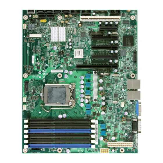
Intel® Server Board S3420GP TPS Overview Server Board Layout ® Figure 1. Intel Server Board S3420GPLX Picture Revision 2.4 Intel order number E65697-010... -
Page 18: Server Board Connector And Component Layout
Overview Intel® Server Board S3420GP TPS 2.2.1 Server Board Connector and Component Layout The following figure shows the board layout of the server board. Each connector and major component is identified by a number or letter, and Table 2 provides the description. -
Page 19: Table 2. Major Board Components
Server Board S3420GPV) External Serial port Front Panel Connector ® Main Power Connector Internal Serial Port (Intel Server Board S3420GPLX and S3420GPLC) CPU Power connector ® DIMM slots (4 slots on Intel Server Board S3420GPV) Revision 2.4 Intel order number E65697-010... -
Page 20: Intel Server Board S3420Gp Mechanical Drawings
Overview Intel® Server Board S3420GP TPS 2.2.2 Intel Server Board S3420GP Mechanical Drawings ® ® Figure 3. Intel Server Board S3420GP – Key Connector and LED Indicator IDENTIFICATION Revision 2.4 Intel order number E65697-010... -
Page 21: Figure 4. Intel ® Server Board S3420Gp - Hole And Component Positions
Intel® Server Board S3420GP TPS Overview ® Figure 4. Intel Server Board S3420GP – Hole and Component Positions Revision 2.4 Intel order number E65697-010... -
Page 22: Figure 5. Intel ® Server Board S3420Gp - Major Connector Pin Location (1 Of 2)
Overview Intel® Server Board S3420GP TPS ® Figure 5. Intel Server Board S3420GP – Major Connector Pin Location (1 of 2) Revision 2.4 Intel order number E65697-010... -
Page 23: Figure 6. Intel ® Server Board S3420Gp -Major Connector Pin Location (2 Of 2)
Intel® Server Board S3420GP TPS Overview ® Figure 6. Intel Server Board S3420GP –Major Connector Pin Location (2 of 2) Revision 2.4 Intel order number E65697-010... -
Page 24: Figure 7. Intel ® Server Board S3420Gp - Primary Side Keepout Zone
Overview Intel® Server Board S3420GP TPS ® Figure 7. Intel Server Board S3420GP – Primary Side Keepout Zone Revision 2.4 Intel order number E65697-010... -
Page 25: Figure 8. Intel ® Server Board S3420Gp - Secondary Side Keepout Zone
Intel® Server Board S3420GP TPS Overview ® Figure 8. Intel Server Board S3420GP – Secondary Side Keepout Zone Revision 2.4 Intel order number E65697-010... -
Page 26: Server Board Rear I/O Layout
Overview Intel® Server Board S3420GP TPS 2.2.3 Server Board Rear I/O Layout The following figure shows the layout of the rear I/O components for the server board. Serial Port A NIC Port 1 (1 Gb) and Dual USB Port Connector... -
Page 27: Functional Architecture
® ® The architecture and design of the Intel Server Board S3420GP is based on the Intel 3420 ® ® Chipset. The chipset is designed for systems based on the Intel Xeon Processor 3400 Series ® ® ® or Intel... -
Page 28: Figure 11. Intel ® Server Board S3420Gp Functional Block Diagram From S3420Gplc
Functional Architecture Intel® Server Board S3420GP TPS ® Figure 11. Intel Server Board S3420GP Functional Block Diagram From S3420GPLC Revision 2.4 Intel order number E65697-010... -
Page 29: Processor Sub-System
Up to 95 W Thermal Design Power (TDP); processors with higher TDP are not supported. ® ® The server board does not support previous generations of the Intel Xeon processors. 3.1.2 Intel Core Processor i3-500 Series and Intel... -
Page 30: Simultaneous Multithreading (Smt)
® Intel Core i3-500 Desktop Processor Series and Intel Pentium Processor G6950. ® RAS (Reliability, Availability, and Serviceability) is not supported on the Intel Server Board S3420GP. 3.2.1 Memory Sizing and Configuration ® The Intel Server Board S3420GP supports various memory module sizes and configurations. -
Page 31: Post Error Codes
Intel® Server Board S3420GP TPS Functional Architecture S3420GP supports: DIMM sizes of 1 GB, 2 GB, 4 GB, and 8 GB. DIMMs composed of DRAM using 2 Gb technology. DRAMs organized as single rank, dual rank, or quad rank DIMMS. -
Page 32: Publishing System Memory
When 4 GB or more of physical memory is installed (physical memory is the memory installed ® as DDR3 DIMMs), the reserved memory is lost. However, the Intel 3420 chipset provides a feature called high-memory reclaim, which allows the BIOS and operating system to remap the lost physical memory into system memory above 4 GB (the system memory is the memory the processor can see). -
Page 33: Memory Map And Population Rules
® 4. The Intel Xeon Processor 3400 Series on the Intel Server Board S3420GP is populated on the processor socket. It has an Integrated Memory Controller (IMC). The IMC provides two DDR3 channels and groups DIMMs on the board into an autonomous memory. -
Page 34: Table 4. Memory Configuration Table
The minimal memory set is {DIMMA1}. DDR3 DIMMs on adjacent slots on the same channel do not need to be identical. ® Each socket supports a maximum of six slots. Standard Intel server boards and systems that ® use the Intel 3420 chipset support three slots per DDR3 channel, two DDR3 channels per ®... -
Page 35: Table 5. Udimm Memory Configuration Rule
Intel® Server Board S3420GP TPS Functional Architecture Channel A Channel B UDIMM This table defines half of the valid memory configurations. You can exchange Channel A DIMMs with the DIMMs on Channel B to get another half. 3.2.4.5 UDIMM Configuration rules... -
Page 36: Intel ® 3420 Chipset Pch
3420 Chipset component is the Platform Controller Hub (PCH). The PCH is designed ® ® for use with Intel processor in a UP server platform. The role of the PCH in Intel Server Board S3420GP is to manage the flow of information between its eleven interfaces: DMI interface to Processor ... -
Page 37: I/O Sub-System
Intel® Server Board S3420GP TPS Functional Architecture PCI Express* Interface PCI Interface SATA Interface USB Host Interface SMBus Host Interface SPI Interface LPC interface to IBMC JTAG interface LAN interface ACPI interface ... -
Page 38: Serial Ata Support
The SATA controller contains two modes of operation – a legacy mode using I/O space and an AHCI mode using memory space. ® Software that uses legacy mode does not have AHCI capabilities. The Intel 3420 Chipset supports the Serial ATA Specification, Revision 1.0a. The Ibex Peak also supports several optional sections of the Serial ATA II: Extensions to Serial ATA 1.0 Specification, Revision 1.0... -
Page 39: Optional Intel Sas Entry Raid Module Axx4Sasmod
SAS Entry RAID Module AXX4SASMOD is detected, the x4 PCI Express* links from the ® PCI switches to the 50-pin PCI Express* connector. The optional Intel SAS Entry RAID Module AXX4SASMOD includes a SAS1064e controller that supports x4 PCI Express* link widths and is a single-function PCI Express* end-point device. - Page 40 Functional Architecture Intel® Server Board S3420GP TPS The ServerEngines* LLC Pilot II Integrated BMC is provided by an embedded ARM9 controller and associated peripheral functionality that is required for IPMI-based server management. Firmware usage of these hardware features is platform-dependant.
-
Page 41: Integrated Bmc Embedded Lan Channel
Intel® Server Board S3420GP TPS Functional Architecture Figure 13. Integrated BMC Hardware 3.6.1 Integrated BMC Embedded LAN Channel The Integrated BMC hardware includes two dedicated 10/100 network interfaces. Interface 1: This interface is available from either of the available NIC ports in system that can be shared with the host. -
Page 42: Serial Ports
Functional Architecture Intel® Server Board S3420GP TPS Give the customer the option to add a dedicated management 100 Mbit LAN interface to the product. Provide additional flash space, enabling the Advanced Management functions to support WS-MAN and CIMON. -
Page 43: Wake-Up Control
Intel® Server Board S3420GP TPS Functional Architecture 3.6.6 Wake-up Control The super I/O contains functionality that allows various events to power on and power off the system. Video Support 3.7.1 Intel Server Board S3420GPLX and Intel Server Board S3420GPLC ®... -
Page 44: Video For Intel Server Board S3420Gpv
Functional Architecture Intel® Server Board S3420GP TPS 2D Mode 2D Video Mode Support (Color Bit) Resolution 8 bpp 16 bpp 24 bpp 32 bpp (Hz) 1440x900 Supported Supported Supported Monitor Refresh Rate (Hz) 1600x1200 Supported Supported 60, 65, 70, 75,... -
Page 45: Network Interface Controller (Nic)
Network Interface Controller (NIC) ® The Intel Server Board S3420GPLX, S3420GPLC and S3420GPV support two network ® interfaces, One is provided from the onboard Intel 82574L GbE PCI Express network controller; ® the other is the onboard Intel 82578 Gigabit Network controller. -
Page 46: I/Oat2)
Intel Architecture Processor. Intel VT-d Technology enables multiple operating systems and applications to run in dependent partitions. A partition behaves like a virtual machine (VM) and provides isolation and protection across partitions. Each partition is allocated its own subset of host physical memory. -
Page 47: 4.1 Feature Support
Intel® Server Board S3420GP TPS Platform Management Platform Management ® ® This chapter is only for The Intel Server Board S3420GPLX and Intel Server Board S3420GPLC. The platform management subsystem is based on the Integrated BMC features of the ServerEngines* Pilot II. The onboard platform management subsystem consists of communication buses, sensors, system BIOS, and server management firmware. -
Page 48: Non-Ipmi Features
Platform Management Intel® Server Board S3420GP TPS Field replaceable unit (FRU) inventory device functionality: The Integrated BMC supports access to system FRU devices using IPMI FRU commands. System event log (SEL) device functionality: The Integrated BMC supports and provides access to a SEL. -
Page 49: Optional Advanced Management Feature Support
The Intel RMM3 provides the Integrated BMC with an additional dedicated network interface. ® The dedicated interface consumes its own LAN channel. Additionally, the Intel RMM3 provides additional flash storage for advanced features like Web Services for Management (WS-MAN). 4.2.2 Keyboard, Video, Mouse (KVM) Redirection The Integrated BMC firmware supports keyboard, video, and mouse redirection over LAN. -
Page 50: Media Redirection
Platform Management Intel® Server Board S3420GP TPS 4.2.2.3 Availability Up to two remote KVM sessions are supported. The default inactivity timeout is 30 minutes; however, this can be changed through the embedded web server. Remote KVM activation does not disable the local system keyboard, video, or mouse. Unless the feature is disabled locally, remote KVM is not deactivated by local system input. -
Page 51: Local Directory Authentication Protocol (Ldap)
The web server is available on all enabled LAN channels. See Appendix B for Integrated BMC core sensors. Management Engine (ME) Intel Management Engine is tied to essential platform functionality. This Management Engine firmware includes the following applications: Platform Clocks – Tune PCH clock silicon to the parameters of a specific board, configure clocks at run time, power management clocks. -
Page 52: Server Management Capability For Intel® Server Board S3420Gpv
Server Management Capability for Intel® Server Board S3420GPV Intel® Server Board S3420GP TPS Server Management Capability for Intel® Server Board S3420GPV Super I/O 5.1.1 Key Features of Super I/O The W83627DHG-P is from the Nuvoton's Super I/O product line. This family features the LPC (Low Pin Count) interface. -
Page 53: Figure 15. Setup Utility - Hardware Monitor Screen Display
Intel® Server Board S3420GP TPS Server Management Capability for Intel® Server Board S3420GPV Advance Boot Boot Main Security Server Management Options Manager Hardware monitor Real-time Temperature and Voltage Status Fan Controller Auto/Manual CPU Fan Altitude 300m/900m/1500m/3000m Board Fan Altitude 300m/900m/1500m/3000m Figure 15. -
Page 54: Fan Controller (Manual)
Server Management Capability for Intel® Server Board S3420GPV Intel® Server Board S3420GP TPS Note: The two options of Hysteresis and Default Fan PWM apply to all the four fans 5.1.3 Fan controller (Manual) Fan controller (Manual) allows the user to configure Fan speed control manually. To access this screen from the Main screen, choose Server Management >... -
Page 55: Figure 16. Setup Utility - Fan Controller (Manual) Display
Intel® Server Board S3420GP TPS Server Management Capability for Intel® Server Board S3420GPV Advanc Secu rit Server Boot Main Boot Manager Management Options Hardware monitor Real-time Temperature and Voltage Status Fan Controller Manual CPU Fan [2 Degree Celsius/3 Degree Celsius/4 Degree Celsius... -
Page 56: Voltage And Temperature Status Screen
Server Management Capability for Intel® Server Board S3420GPV Intel® Server Board S3420GP TPS Setup Item Options Help Text Comments CPU Fan Altitude 300m/900m/1500m/3000m Select CPU FAN default PWM according to altitude under Auto mode System Fan Altitude 300m/900m/1500m/3000m Select Board Fan default PWM... -
Page 57: Smbios
Server Board S3420GPLC with iBMC, the ® SMBIOS type 1, 2, 3 are from FRUSDR by BMC. But on Intel Server Board S3420GPV, SMBIOS type 1, 2, 3 are stored in BIOS flash during manufactory build, so it’s also non-volatile data storage. -
Page 58: Figure 18. Event Log Viewer
Server Management Capability for Intel® Server Board S3420GPV Intel® Server Board S3420GP TPS Error Manager Event Info Time M-BIT MEM ECC Error CPU0 Ch 0 Dimm0 10/15/09 15:12:23 S-BIT MEM ECC Error CPU0 Ch 0 Dimm0 10/15/09 15:11:25... -
Page 59: Bios User Interface
Platform name Total memory detected (Total size of all installed DDR3 DIMMs) Processor information (Intel branded string, speed, and number of physical processor identified) Keyboards detected (if plugged in) Mouse devices detected (if plugged in) -
Page 60: Operation
6.3.1.2 Entering BIOS Setup To enter the BIOS Setup, press the F2 function key during boot time when the OEM or Intel logo displays. The following message displays on the diagnostics screen and under the Quiet Boot logo screen: Press <F2>... -
Page 61: Table 17. Bios Setup: Keyboard Command Bar
Intel® Server Board S3420GP TPS BIOS User Interface feature’s value may or may not be changed. If a value cannot be changed, its field is made inaccessible and appears grayed out. Table 17. BIOS Setup: Keyboard Command Bar Option Description <Enter>... -
Page 62: Server Platform Setup Utility Screens
BIOS User Interface Intel® Server Board S3420GP TPS Option Description <F10> Save and Exit Pressing <F10> causes the following message to display: Save configuration and reset? If “Yes” is highlighted and <Enter> is pressed, all changes are saved and the Setup is exited. -
Page 63: Figure 19. Setup Utility - Main Screen Display
Intel® Server Board S3420GP TPS BIOS User Interface Advance Main Security Server Management Boot Options Boot Manager Logged in as <Administrator or User> <Platform Identification String> Platform ID System BIOS Version SXXXX.86B.xx.yy.zzzz Build Date <MM/DD/YYYY>... -
Page 64: Advanced Screen
BIOS User Interface Intel® Server Board S3420GP TPS Setup Item Options Help Text Comments Size Information only. Displays the total physical memory installed in the system, in MB or GB. The term physical memory indicates the total memory discovered in the form of installed DDR3 DIMMs. -
Page 65: Figure 20. Setup Utility - Advanced Screen Display
Intel® Server Board S3420GP TPS BIOS User Interface Advance Main Security Server Management Boot Options Boot Manager ► Processor Configuration ► Memory Configuration ► Mass Storage Controller Configuration ► Serial Port Configuration ► USB Configuration ► PCI Configuration ► System Acoustic and Performance Configuration ... -
Page 66: Figure 21. Setup Utility - Processor Configuration Screen Display
BIOS User Interface Intel® Server Board S3420GP TPS Advanced Processor Configuration Processor Socket CPU 1 Processor ID <CPUID> Processor Frequency <Proc Freq> Microcode Revision <Rev data> L1 Cache RAM Size of Cache L2 Cache RAM Size of Cache L3 Cache RAM... - Page 67 Intel® Server Board S3420GP TPS BIOS User Interface Setup Item Options Help Text Comments L2 Cache RAM Information only. Size of the Processor L2 Cache L3 Cache RAM Information only. Size of the Processor L3 Cache. Processor Version Information only. ID string from the Processor.
-
Page 68: Figure 22. Setup Utility - Memory Configuration Screen Display
BIOS User Interface Intel® Server Board S3420GP TPS Setup Item Options Help Text Comments Adjacent Cache Line Enabled [Enabled] - Cache lines are fetched in pairs Prefetch (even line + odd line). Disabled [Disabled] - Only the current cache line required is fetched. - Page 69 Mass Storage Controller Screen The Mass Storage screen allows the user to configure the SATA/SAS controller when it is present on the baseboard, midplane, or backplane of an Intel system. To access this screen from the Main menu, select Advanced > Mass Storage.
-
Page 70: Figure 23. Setup Utility - Mass Storage Controller Configuration Screen Display
Advanced Host Controller Interface. [Intel ESRT2] - Supports RAID ® 0/1/10 with Intel Embedded Software RAIDII Technology. [Matrix RAID] – Supports RAID ® levels 0/1/10 and 5 with Intel Matrix Storage RAID Technology. Revision 2.4 Intel order number E65697-010... -
Page 71: Figure 24. Setup Utility - Serial Port Configuration Screen Display
Intel® Server Board S3420GP TPS BIOS User Interface Setup Item Options Help Text Comments SATA Port 0 < Not Information only. This field is Installed/Drive unavailable when RAID Mode is information> enabled. SATA Port 1 < Not Information only. This field is... -
Page 72: Figure 25. Setup Utility - Usb Controller Configuration Screen Display
BIOS User Interface Intel® Server Board S3420GP TPS Setup Item Options Help Text Select Serial port A interrupt request (IRQ) line. Serial B Enabled Enable or Disable Serial port B. Enable Disabled Address 3F8h Select Serial port B base I/O address. -
Page 73: Table 24. Setup Utility - Usb Controller Configuration Screen Fields
Intel® Server Board S3420GP TPS BIOS User Interface Table 24. Setup Utility – USB Controller Configuration Screen Fields Setup Item Options Help Text Comments Detected USB Information only. Shows the number Devices of USB devices in the system. USB Controller... -
Page 74: Figure 26. Setup Utility - Pci Configuration Screen Display
BIOS User Interface Intel® Server Board S3420GP TPS Advanced PCI Configuration Maximize Memory below 4GB Enabled/Disabled Memory Mapped I/O above 4GB Enabled/Disabled Onboard Video Enabled/Disabled Dual Monitor Video Enabled/Disabled Onboard NIC1 ROM Enabled/Disabled Onboard NIC2 ROM Enabled/Disabled... -
Page 75: Figure 27. Setup Utility - System Acoustic And Performance Configuration Screen Display
Intel® Server Board S3420GP TPS BIOS User Interface Setup Item Options Help Text Comments Onboard NIC iSCSI Enabled If enabled. loads the embedded option ROM for This option is grayed out the onboard network controllers. and not accessible if either... -
Page 76: Figure 28. Setup Utility - Security Configuration Screen Display
The Security screen allows the user to enable and set the user and administrative password and to lock out the front panel buttons so they cannot be used. ® Trusted Platform Module (TPM) security is NOT supported on the Intel Server S3420GP board. To access this screen from the Main screen, select Security. - Page 77 Intel® Server Board S3420GP TPS BIOS User Interface Setup Item Options Help Text Comments User Password Status <Installed Information only. Indicates the status of the user Not Installed> password. Set Administrator [123aBcD] Administrator password is used to This option is only to control...
-
Page 78: Figure 29. Setup Utility - Server Management Configuraiton Screen Display
BIOS User Interface Intel® Server Board S3420GP TPS Advance Main Security Server Management Boot Options Boot Manager Assert NMI on SERR Enabled/Disabled Assert NMI on PERR Enabled/Disabled Resume on AC Power Loss Stay Off/Last state/Reset Clear System Event Log... -
Page 79: Figure 30. Setup Utility - Console Redirection Screen Display
Disabled complete booting before the timer expires, the BMC resets the system and an error is logged. Requires OS support or Intel Management Software. O/S Boot Watchdog Power Off If the OS boot watchdog timer is enabled, this is the... -
Page 80: Table 29. Setup Utility - Console Redirection Configuration Fields
BIOS User Interface Intel® Server Board S3420GP TPS Table 29. Setup Utility – Console Redirection Configuration Fields Setup Item Options Help Text Console Redirection Disabled Console redirection allows a serial port to be used for server management tasks. Serial Port A [Disabled] - No console redirection. -
Page 81: Figure 31. Setup Utility - Server Management System Information Screen Display
Intel® Server Board S3420GP TPS BIOS User Interface Server Management System Information Board Part Number Board Serial Number System Part Number System Serial Number Chassis Part Number Chassis Serial Number BMC Firmware Revision HSC Firmware Revision ME Firmware Revision... -
Page 82: Figure 32. Setup Utility - Boot Options Screen Display
BIOS User Interface Intel® Server Board S3420GP TPS Advance Main Security Server Management Boot Options Boot Manager System Boot Timeout <0 - 65535> Boot Option #1 <Available Boot devices> Boot Option #2 <Available Boot devices> Boot Option #x <Available Boot devices>... -
Page 83: Figure 33. Setup Utility - Delete Boot Option Screen Display
Intel® Server Board S3420GP TPS BIOS User Interface Setup Item Options Help Text Comments this group. these devices are available in the system. BEV Device Order Set the order of the legacy devices in Visible when one or more of this group. -
Page 84: Figure 34. Setup Utility - Hard Disk Order Screen Display
BIOS User Interface Intel® Server Board S3420GP TPS Table 32. Setup Utility – Delete Boot Option Fields Setup Item Options Help Text Delete Boot Option Select one to Delete Remove an EFI boot option from the boot order. Internal EFI Shell 6.3.2.6.2... -
Page 85: Figure 36. Setup Utility - Floppy Order Screen Display
Intel® Server Board S3420GP TPS BIOS User Interface Table 34. Setup Utility – CDROM Order Fields Setup Item Options Help Text CDROM #1 Available Set system boot order by selecting the boot Legacy devices option for this position. for this Device group. -
Page 86: Loading Bios Defaults
BIOS User Interface Intel® Server Board S3420GP TPS Table 36. Setup Utility – Network Device Order Fields Setup Item Options Help Text Network Device #1 Available Set system boot order by selecting the boot Legacy devices option for this position. - Page 87 Intel® Server Board S3420GP TPS BIOS User Interface IPMI command (set System Boot options command) Int15 AX=DA209 Choosing Load User Defaults from the Exit page of the BIOS Setup loads user set defaults instead of the BIOS factory defaults.
-
Page 88: Connector/Header Locations And Pin-Outs
Connector/Header Locations and Pin-outs Intel® Server Board S3420GP TPS Connector/Header Locations and Pin-outs Board Connector Information The following section provides detailed information regarding all connectors, headers, and jumpers on the server board. It lists all connector types available on the board and the corresponding reference designators printed on the silkscreen. -
Page 89: System Management Headers
Intel Remote Management Module 3. This server board does not support third-party management cards. ® ® Note: This connector is not compatible with the Intel Remote Management Module (Intel ® ® RMM) or the Intel Remote Management Module 2 (Intel RMM2). -
Page 90: Lcp/Ipmb Header
Connector/Header Locations and Pin-outs Intel® Server Board S3420GP TPS ® Table 41. Intel RMM3 Connector Pin-out (J2C1) Signal Name Signal Name P3V3_AUX RMII_IBMC_RMM3_MDIO P3V3_AUX RMII_IBMC_RMM3_MDC RMII_IBMC_RMM3_RXD1 RMII_IBMC_RMM3_RXD0 RMII_IBMC_RMM3_CRS_DV CLK_50M_RMM3 RMII_IBMC_RMM3_RX_ER RMII_IBMC_RMM3_TX_EN RMII_IBMC_RMM3_TXD0 RMII_IBMC_RMM3_TXD1 P3V3_AUX SPI_IBMC_BK_CS_N P3V3_AUX TP_RMM3_SPI_WE P3V3_AUX SPI_IBMC_BK_DO SPI_IBMC_BK_CLK... -
Page 91: Sgpio Header
Front Control Panel Connector ® The server board provides a 24-pin SSI front panel connector (J1C1) for use with Intel third-party chassis. The following table provides the pin-out for this connector. Table 45. Front Panel SSI Standard 24-pin Connector Pin-out (J1C1) -
Page 92: Power Button
® ® ® The Intel Server Board S3420GP that uses the Intel Xeon Processor 3400 Series has a system status indicator LED on the front panel. This indicator LED has specific states and corresponding interpretation as shown in the following table. -
Page 93: I/O Connectors
Intel® Server Board S3420GP TPS Connector/Header Locations and Pin-outs Color State Criticality Description Green ~1 Hz blink Degraded System degraded: Non-critical temperature threshold asserted. Non-critical voltage threshold asserted. Non-critical fan threshold asserted. Fan redundancy lost, sufficient system cooling maintained. -
Page 94: Rear Nic And Usb Connector
Connector/Header Locations and Pin-outs Intel® Server Board S3420GP TPS Signal Name Description V_IO_B_CONN Blue (analog color signal B) TP_VID_CONN_B4 No connection Ground Ground Ground Ground TP_VID_CONN_B9 No connection Ground TP_VID_CONN_B11 No connection V_IO_DDCDAT DDCDAT V_IO_HSYNC_CONN HSYNC (horizontal sync) V_IO_VSYNC_CONN VSYNC (vertical sync) -
Page 95: Sata
50-pin PCI Express* Connector ® ® The Intel Server Board S3420GPLX provides one 50-pin PCI Express* connector for Intel SAS Entry RAID Module AXX4SASMOD. The pin configuration is identical and defined in the following table. Table 51. 50-pin PCI Express* Connector Pin-out (J2H1) -
Page 96: Serial Port Connectors
Connector/Header Locations and Pin-outs Intel® Server Board S3420GP TPS Signal Name Signal Name P3V3 P3V3 P3V3 P3V3 P3V3 P3V3 7.5.5 Serial Port Connectors The server board provides one external DB9 Serial A port (J8A1) and one internal 9-pin serial B header (J1B2). -
Page 97: Pci Express* Slot/Pci Slot/Riser Card Slot
Signal Name USB_N USB_P ® One 2x5 connectors (J3F2) on the server board provides an option to support an Intel Z-U130 Value Solid State Drive. The following table defines the pin-out of the connector. ® Table 56. Pin-out of Internal USB Connector for low-profile Intel... - Page 98 Connector/Header Locations and Pin-outs Intel® Server Board S3420GP TPS Signal Description Signal Description SMCLK PU_S6_SMBCLK JTAG2 P3V3_RISER_A5 SMDATA PU_S6_SMBDAT JTAG3 JTAG_S6_TDI JTAG4 +3.3V P3V3 JTAG5 P3V3_RISER_A8 JTAG1 JTAG_S6_TRST_N +3_3V P3V3 +3.3VAUX P3V3_AUX +3_3V P3V3 WAKE_N FM_PE_WAKE_N PERST_N RST_PE_S236_N_R1 RSVD REFCLKP...
- Page 99 Intel® Server Board S3420GP TPS Connector/Header Locations and Pin-outs Signal Description Signal Description PRSNT2_N PERN7 P2E_CPU_S6_RXP<0> End of x8 End of x8 PETP8 RSVD PETN8 PERP8 PERN8 PETP9 PETN9 PERP9 PERN9 PETP10 PETN10 PERP10 PERN10 PExP11 PETN11 PERP11 PERN11 PETP12...
- Page 100 Connector/Header Locations and Pin-outs Intel® Server Board S3420GP TPS Signal Signal Signal Signal HSIN[3] JTAG2/TCk SMCLK RESERVED JTAG3/TDI SMDAT PRSNT2# JTAG4/TDO RESERVED JTAG5/TMS +3.3V RESERVED HSOP[4] +3.3V JTAG1/TRST# HSON[4] HSIP[4] +3.3V 3.3VAUX HSIN[4] PERST# WAKE# RESERVED HSOP[5] REFCLK+ HSON[5] HSIP[5]...
- Page 101 Intel® Server Board S3420GP TPS Connector/Header Locations and Pin-outs Pin# Signal Pin# Signal Pin# Signal Pin# Signal +3.3V JTAG1 PERP2 +3.3V 3.3VAUX PERN2 PERST_N WAKE_N PETP3 RSVD PETN3 REFCLK+ PERP3 REFCLK- PETP0 PERN3 RSVD PETN0 PRSNT2_N PERP0 RSVD One PCI X32 connector (J1B1)
-
Page 102: Fan Headers
Connector/Header Locations and Pin-outs Intel® Server Board S3420GP TPS Fan Headers The server board provides five SSI-compliant 4-pin fan headers to be used as the CPU and chassis. The pin configuration for each of the 4-pin fan headers is identical and defined in the following table. -
Page 103: Jumper Blocks
Intel® Server Board S3420GP TPS Jumper Blocks Jumper Blocks The server board has several 3-pin jumper blocks that can be used to configure, protect, or recover specific features of the server board. Figure 39. Jumper Blocks (J1A2, J1F1, J1F3, J1F2 and J1F5) Table 59. -
Page 104: Cmos Clear And Password Reset Usage Procedure
The CMOS Clear (J1F5) and Password Reset (J1F2) recovery features are designed such that the desired operation can be achieved with minimal system downtime. The usage procedure for these two features has changed from previous generation Intel server boards. The following procedure outlines the new usage model. -
Page 105: Integrated Bmc Force Update Procedure (Only For The Intel Server Board S3420Gplx And S3420Gplc)
Intel® Server Board S3420GP TPS Jumper Blocks Integrated BMC Force Update Procedure (only for the Intel Server Board ® S3420GPLX and S3420GPLC) When performing the standard Integrated BMC firmware update procedure, the update utility places the Integrated BMC into an update mode, allowing the firmware to load safely onto the flash device. -
Page 106: Bios Recovery Jumper
Jumper Blocks Intel® Server Board S3420GP TPS Move jumper from the default operating position (covering pins 1 and 2) to the enabled position (covering pins 2 and 3). Close the server chassis. Reconnect the AC cord and power up the server. -
Page 107: Intel Light Guided Diagnostics
The server board has several on-board diagnostic LEDs to assist in troubleshooting board-level issues. This section shows where each LED is located on the server board and describes the function of each LED. System Status LED (For the Intel Server Board S3420GPLX and ®... -
Page 108: Post Code Diagnostic Leds
Intel® Light Guided Diagnostics Intel® Server Board S3420GP TPS Post Code Diagnostic LEDs During the system boot process, the BIOS executes several platform configuration processes, each of which is assigned a specific hex POST code number. As each configuration routine is started, the BIOS displays the POST code on the POST code diagnostic LEDs found on the back edge of the server board. -
Page 109: 10. Design And Environmental Specifications
Disclaimer Note: Intel Corporation server boards contain a number of high-density VLSI and power delivery components that need adequate airflow to cool. Intel ensures through its own chassis development and testing that when Intel server building blocks are used together, the fully integrated system will meet the intended thermal requirements of these components. -
Page 110: 10.3 Server Board Power Requirements
Intel® Server Board S3420GP TPS 10.3 Server Board Power Requirements ® This section provides power supply design guidelines for a system using the Intel Server Board S3420GP, including voltage and current specifications, and power supply on/off sequencing characteristics. The following diagram shows the power distribution implemented on this server board. -
Page 111: 10.4 Power Supply Output Requirements
This section is for reference purposes only. The intent is to provide guidance to system designers to determine a power supply for use with this server board. This section specifies the ® power supply requirements Intel used to develop a power supply for the Intel Server System SR1630GP and SR1630HGP. -
Page 112: Voltage Regulation
Design and Environmental Specifications Intel® Server Board S3420GP TPS 10.4.4 Voltage Regulation The power supply output voltages must stay within the following voltage limits when operating at steady state and dynamic loading conditions. These limits include the peak-peak ripple/noise. All outputs are measured with reference to the return remote sense signal (ReturnS). -
Page 113: Common Mode Noise
Intel® Server Board S3420GP TPS Design and Environmental Specifications sensing through the submission of Bode plots. Closed-loop stability is ensured at the maximum and minimum loads as applicable. 10.4.8 Common Mode Noise The Common Mode noise on any output does not exceed 350 mV pk-pk over the frequency band of 10 Hz to 20 MHz. -
Page 114: Figure 41. Output Voltage Timing
Design and Environmental Specifications Intel® Server Board S3420GP TPS Note: The 5 VSB output voltage rise time should be from 1.0 ms to 25.0 ms. Figure 41. Output Voltage Timing Table 70. Turn On/Off Timing Item Description Minimum Maximum Units... -
Page 115: Residual Voltage Immunity In Standby Mode
Intel® Server Board S3420GP TPS Design and Environmental Specifications Item Description Minimum Maximum Units Duration for which the 5 VSB output voltage stays Msec 5VSB_holdup within regulation after loss of AC. Figure 42. Turn On/Off Timing (Power Supply Signals) 10.4.11... -
Page 116: Table 71. Over-Current Protection (Ocp)
Design and Environmental Specifications Intel® Server Board S3420GP TPS Table 71. Over-Current Protection (OCP) Voltage Over Current Limit +3.3V +12V -12V 0.625A 5VSB 10.4.12.2 Over-Voltage Protection (OVP) The power supply over-voltage protection is locally sensed. The power supply shuts down and latches off after an over-voltage condition occurs. -
Page 117: 11. Regulatory And Certification Information
UL 60950-1 Recognition (USA 11.1.2 Product EMC Compliance – Class A Compliance Note: This product requires complying with Class A EMC requirements. However, Intel targets a 10 db margin to support customer enablement. AS/NZS CISPR 22 Emissions (Australia/New Zealand) ... -
Page 118: 11.1.3 Certifications/Registrations/Declarations
11.1.4 Product Ecology Requirements Intel restricts the use of banned substances in accordance with world wide product ecology regulatory requirements. Suppliers Declarations of Conformity to the banned substances must be obtained from all suppliers; and a Material Declaration Data Sheet (MDDS) must be produced to illustrate compliance. -
Page 119: 11.2 Product Regulatory Compliance Markings
Intel® Server Board S3420GP TPS Regulatory and Certification Information 11.2 Product Regulatory Compliance Markings The server board is provided with the following regulatory marks. Regulatory Compliance Region Marking UL Mark USA/Canada CE Mark Europe EMC Marking (Class A) Canada CANADA ICES-003 CLASS A... - Page 120 Regulatory and Certification Information Intel® Server Board S3420GP TPS Regulatory Compliance Region Marking Other Recycling Package Other Recycling Package Marks Marking (Marked on packaging label) Other Recycling Package CA. Lithium Perchlorate Perchlorate Material – Special handling may insert apply. See Marking www.dtsc.ca.gov/hazardouswaste/perchlorate...
-
Page 121: 11.3 Electromagnetic Compatibility Notices
Intel® Server Board S3420GP TPS Regulatory and Certification Information 11.3 Electromagnetic Compatibility Notices 11.3.1 FCC Verification Statement (USA) This device complies with Part 15 of the FCC Rules. Operation is subject to two conditions: (1) This device may not cause harmful interference, and (2) this device must accept any interference received, including interference that may cause undesired operation. -
Page 122: Ices-003 (Canada)
Regulatory and Certification Information Intel® Server Board S3420GP TPS 11.3.2 ICES-003 (Canada) Cet appareil numérique respecte les limites bruits radioélectriques applicables aux appareils numériques de Classe B prescrites dans la norme sur le matériel brouilleur: “Appareils Numériques”, NMB-003 édictée par le Ministre Canadian des Communications. -
Page 123: Bsmi (Taiwan)
English translation of the notice above: 1. Type of Equipment (Model Name): On License and Product 2. Certification No.: On RRL certificate. Obtain certificate from local Intel representative 3. Name of Certification Recipient: Intel Corporation 4. Date of Manufacturer: Refer to date code on product 5. -
Page 124: Appendix A: Integration And Usage Tips
Processor 3400 Series with 95 W and less Thermal Design ® ® Power (TDP). Does not support previous generations of the Intel Xeon processor. On the back edge of the server board are diagnostic LEDs that display a sequence of ... -
Page 125: Appendix B: Integrated Bmc Sensor Tables
Intel® Server Board S3420GP TPS Appendix B: Integrated BMC Sensor Tables Appendix B: Integrated BMC Sensor Tables This appendix lists the sensor identification numbers and information about the sensor type, name, supported thresholds, assertion and de-assertion information, and a brief description of the sensor purpose. - Page 126 Appendix B: Integrated BMC Sensor Tables Intel® Server Board S3420GP TPS Rearm Sensors The rearm is a request for the event status for a sensor to be rechecked and updated upon a transition between good and bad states. Rearming the sensors can be done manually or automatically.
-
Page 127: Table 73. Integrated Bmc Core Sensors
Intel® Server Board S3420GP TPS Appendix B: Integrated BMC Sensor Tables Table 73. Integrated BMC Core Sensors Sensor Name Sensor # Platform Sensor Type Event / Event Offset Contrib. To Assert / Readable Event Rearm Stand- Applicability Reading Triggers System... - Page 128 Appendix B: Integrated BMC Sensor Tables Intel® Server Board S3420GP TPS Sensor Name Sensor # Platform Sensor Type Event / Event Offset Contrib. To Assert / Readable Event Rearm Stand- Applicability Reading Triggers System Value / Data Type Status assert...
- Page 129 Intel® Server Board S3420GP TPS Appendix B: Integrated BMC Sensor Tables Sensor Name Sensor # Platform Sensor Type Event / Event Offset Contrib. To Assert / Readable Event Rearm Stand- Applicability Reading Triggers System Value / Data Type Status assert...
- Page 130 Appendix B: Integrated BMC Sensor Tables Intel® Server Board S3420GP TPS Sensor Name Sensor # Platform Sensor Type Event / Event Offset Contrib. To Assert / Readable Event Rearm Stand- Applicability Reading Triggers System Value / Data Type Status assert...
-
Page 131: Appendix C: Post Code Diagnostic Led Decoder
Intel® Server Board S3420GP TPS Appendix C: POST Code Diagnostic LED Decoder Appendix C: POST Code Diagnostic LED Decoder During the system boot process, the BIOS executes a number of platform configuration processes, each of which is assigned a specific hex POST code number. As each configuration routine is started, the BIOS displays the POST code to the POST Code Diagnostic LEDs on the back edge of the server board. -
Page 132: Table 75. Diagnostic Led Post Code Decoder
Appendix C: POST Code Diagnostic LED Decoder Intel® Server Board S3420GP TPS Table 75. Diagnostic LED POST Code Decoder Diagnostic LED Decoder O = On, X=Off Checkpoint Upper Nibble Lower Nibble Description Host Processor Early processor initialization (flat32.asm) where system BSP is selected... - Page 133 Intel® Server Board S3420GP TPS Appendix C: POST Code Diagnostic LED Decoder Diagnostic LED Decoder O = On, X=Off Checkpoint Upper Nibble Lower Nibble Description 0x78h Resetting the console controller 0x79h Disabling the console controller 0x7Ah Enabling the console controller...
- Page 134 Appendix C: POST Code Diagnostic LED Decoder Intel® Server Board S3420GP TPS Diagnostic LED Decoder O = On, X=Off Checkpoint Upper Nibble Lower Nibble Description Started connecting drivers 0xE6h DXE Drivers 0xE7h Waiting for user input 0xE8h Checking password 0xE9h...
-
Page 135: Appendix D: Post Code Errors
Intel® Server Board S3420GP TPS Appendix D: POST Code Errors Appendix D: POST Code Errors Whenever possible, the BIOS outputs the current boot progress codes on the video screen. Progress codes are 32-bit quantities plus optional data. The 32-bit numbers include class, subclass, and operation information. - Page 136 Appendix D: POST Code Errors Intel® Server Board S3420GP TPS Error Code Error Message Response 8120 Processor 01 thermal trip error on last boot Pause 8121 Processor 02 thermal trip error on last boot Pause 8130 Processor 01 disabled Pause...
- Page 137 Intel® Server Board S3420GP TPS Appendix D: POST Code Errors Error Code Error Message Response 854B DIMM_C4 Disabled. Pause 854C DIMM_D1 Disabled. Pause 854D DIMM_D2 Disabled. Pause 854E DIMM_D3 Disabled. Pause 854F DIMM_D4 Disabled. Pause 8560 DIMM_A1 Component encountered a Serial Presence Detection (SPD) fail error.
- Page 138 Appendix D: POST Code Errors Intel® Server Board S3420GP TPS Error Code Error Message Response 85AA DIMM_C3 Uncorrectable ECC error encountered. Pause 85AB DIMM_C4 Uncorrectable ECC error encountered. Pause 85AC DIMM_D1 Uncorrectable ECC error encountered. Pause 85AD DIMM_D2 Uncorrectable ECC error encountered.
-
Page 139: Table 77. Post Error Beep Codes
Intel® Server Board S3420GP TPS Appendix D: POST Code Errors Error Code Error Message Response 0xA5A4 PCI Express* IBIST error. Pause 0xA6A0 DXE boot services driver Not enough memory available to shadow a legacy option ROM. No Pause POST Error Beep Codes The following table lists POST error beep codes. -
Page 140: Appendix E: Supported Intel® Server Chassis
Appendix E: Supported Intel® Server Chassis Intel® Server Board S3420GP TPS Appendix E: Supported Intel® Server Chassis ® The Intel Server Board S3420GP is supported in the following Intel server chassis. Please refer to the latest Configuration Guide for detailed information at http://www.intel.com/support/motherboards/server/s3420gp/sb/CS-030741.htm. ® Intel Server Chassis SR1630 ... -
Page 141: Glossary
Intel® Server Board S3420GP TPS Glossary Glossary This appendix contains important terms used in this document. For ease of use, numeric entries are listed first (for example, “82460GX”) followed by alpha entries (for example, “AGP 4x”). Acronyms are followed by non-acronyms. - Page 142 Glossary Intel® Server Board S3420GP TPS Term Definition I/O Controller Hub ICMB Intelligent Chassis Management Bus IERR Internal Error I/O and Firmware Bridge Independent Loading Mechanism Integrated Memory Controller INTR Interrupt I/OAT I/O Acceleration Technology I/O Hub Internet Protocol IPMB...
- Page 143 Intel® Server Board S3420GP TPS Glossary Term Definition Pulse-Width Modulation QuickPath Interconnect Random Access Memory RASUM Reliability, Availability, Serviceability, Usability, and Manageability RISC Reduced Instruction Set Computing RMII Reduced Media-Independent Interface Read Only Memory Real-Time Clock (Component of ICH peripheral chip on the server board)
-
Page 144: Reference Documents
Reference Documents Intel® Server Board S3420GP TPS Reference Documents Refer to the following documents for additional information: ® Intel Server Board S3420GP BIOS External Product Specification ® Intel Server Board S3420GP Common Core Integrated BMC External Product Specification Revision 2.4...
Need help?
Do you have a question about the S3420GPLC - Server Board Motherboard and is the answer not in the manual?
Questions and answers