Intel SE7520AF2 User Manual
User guide
Hide thumbs
Also See for SE7520AF2:
- Spares parts list & configuration manual (13 pages) ,
- Technical product specification (256 pages) ,
- Operating manual (34 pages)

Related Manuals for Intel SE7520AF2


Summary of Contents for Intel SE7520AF2
- Page 1 Intel® Server Board SE7520AF2 User Guide ® A Guide for Technically Qualified Assemblers of Intel Identified Subassemblies/Products Order Number: C63389-003...
- Page 2 Intel’s own chassis are designed and tested to meet the intended thermal requirements of these components when the fully integrated system is used together. It is the responsibility of the system integrator that chooses not to use Intel developed server building blocks to consult vendor datasheets and operating parameters to determine the amount of airflow required for their specific application and environmental conditions.
- Page 3 Manual Organization Chapter 1 provides a brief overview of the Server Board SE7520AF2. In this chapter, you will find a list of the server board features, photos of the product, and product diagrams to help you identify components and their locations.
-
Page 4: Additional Information And Software
Preface For information about which accessories, memory, processors, and third-party hardware have been tested and can be used with your board, and for ordering information for Intel products, see http://support.intel.com/support/motherboards/server/SE7520AF2/. Additional Information and Software If you need more information about this product or information about the accessories that can be used with this server board, use the following resources. -
Page 5: Safety Information
Before computer integration, make sure that the chassis, power supply, and other modules have passed EMC testing using a server board with a microprocessor from the same family (or higher) and operating at the same (or higher) speed as the microprocessor used on this server board. Intel® Server Board SE7520AF2 User Guide... - Page 6 Take care to grip with, but not squeeze, the pliers or other tool you use to remove a jumper, or you may bend or break the stake pins on the board. Intel® Server Board SE7520AF2 User Guide...
-
Page 7: Safety Cautions
Safety Cautions Read all caution and safety statements in this document before performing any of the instructions. See also Intel Server Boards and Server Chassis Safety Information on the Resource CD and/or at http://support.intel.com/support/motherboards/server/safecert.htm. SAFETY STEPS: Whenever you remove the chassis covers to access the inside of the system, follow these steps: Turn off all peripheral devices connected to the system. - Page 8 Lisez attention toutes les consignes de sécurité et les mises en garde indiquées dans ce document avant de suivre toute instruction. Consultez Intel Server Boards and Server Chassis Safety Information sur le CD Resource CD ou bien rendez-vous sur le site http://support.intel.com/support/motherboards/server/safecert.htm.
- Page 9 Instrucciones de seguridad importantes Lea todas las declaraciones de seguridad y precaución de este documento antes de realizar cualquiera de las instrucciones. Vea Intel Server Boards and Server Chassis Safety Information en el CD Resource y/o en http://support.intel.com/support/motherboards/server/safecert.htm. INSTRUCCIONES DE SEGURIDAD: Cuando extraiga la tapa del chasis para acceder al interior del sistema, siga las siguientes instrucciones: Apague todos los dispositivos periféricos conectados al sistema.
-
Page 10: Table Of Contents
Power Light Does Not Light ..................36 No Characters Appear on Screen ................37 Characters Are Distorted or Incorrect..............38 System Cooling Fans Do Not Rotate Properly ............38 Diskette Drive Activity Light Does Not Light ............38 Intel® Server Board SE7520AF2 User Guide... - Page 11 FCC Verification Statement (USA) ................47 ICES-003 (Canada) ..................... 48 Europe (CE Declaration of Conformity) ..............48 VCCI (Japan) ....................... 48 BSMI (Taiwan)......................49 RRL (Korea) ........................ 49 CNCA (CCC-China)..................... 49 ® Intel Server Issue Report Form............... 53 Intel® Server Board SE7520AF2 User Guide...
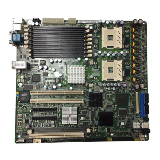
- Page 12 Contents Figures Figure 1. Intel ® Server Board SE7520AF2.................. 1 Figure 2. Server Board Connector and Header Locations............4 Figure 3. Configuration Jumper Location..................5 Figure 4. Back Panel Connectors ....................6 Figure 5. Four DIMM Memory Mirroring..................8 Figure 6. Six DIMM Memory Mirroring ..................8 Figure 7.
-
Page 13: Server Board Features
PCI cards from the system without removing the system AC power supply. The hot plug option may not be available in your geography, contact your Intel representative for more details. The other version does not provide PCI hot plug features. This document describes features of both versions of the server board. -
Page 14: Table 1. Server Board Features
Table 1. Server Board Features Feature Description Processors Up to two Intel® Xeon processors with an 800 MHz Front Side Bus (FSB). DDR2-400 MHz compliant registered ECC DIMMs for up to 16 GB of system Memory memory in a dual-channel architecture... - Page 15 Intel® Light Guided Diagnostics on critical FRU devices, such as processors, memory, and power Front panel LCD connectors for use with the Intel® Local Control Panel Flexible management controller to support Standard and Advanced Management modules SSI-EEB3.5 compliant form factor...
-
Page 16: Connector And Header Locations
DIMM Sockets (left to right: GG Battery Serial B Header DIMM4A, DIMM4B, DIMM3A, DIMM3B, DIMM2A, DIMM2B, DIMM1A, DIMM1B) CPU1 Fault LED HH HSBP B Header ICMB Header Figure 2. Server Board Connector and Header Locations Intel® Server Board SE7520AF2 User Guide... -
Page 17: Configuration Jumpers
BIOS by loading the BIOS code into the flash device from a bootable recovery device. This jumper is typically used when the BIOS has become corrupted. These pins should not be jumpered for normal operation. Intel® Server Board SE7520AF2 User Guide... -
Page 18: Back Panel Connectors
1000 Mbps connection NOTE Hot-plug SKU only: If the PCI Hot-plug board and the Intel® Server Chassis SC5300 PCI Hot Plug Upgrade kit are installed, the LEDs in the I/O port area provide attention information for PCI slots 1, 3, 4, and 5. -
Page 19: Hardware Requirements
Processor Up to two Intel® Xeon™ processors can be used. These must have frequencies starting at 2.8 GHz using the 90 nanometer technology and utilizing an 800 MHz front side bus. Previous generations of the Intel®... -
Page 20: Figure 5. Four Dimm Memory Mirroring
If the DIMM in socket 3A fails, the DIMM in socket 4B takes over. Empty Empty Mirror Primary Mirror Primary Mirror Primary Figure 5. Four DIMM Memory Figure 7. Eight DIMM Memory Figure 6. Six DIMM Memory Mirroring Mirroring Mirroring Intel® Server Board SE7520AF2 User Guide... -
Page 21: Power Supply
DIMM in that channel. Power Supply A power supply with a minimum rating of 600 Watts is recommended. Your power supply must provide a minimum of 2A of 5V standby current or the board will not boot. Intel® Server Board SE7520AF2 User Guide... -
Page 22: Hardware Installations And Upgrades
DIMM3B, DIMM3A, DIMM4B, DIMM4A, starting from the edge of the board. DIMM4A is the socket closest to the center of the board. See “System Memory” for a discussion of the memory requirements and options, and Tested Memory List for a list of tested DIMMs. Intel® Server Board SE7520AF2 User Guide... -
Page 23: Installing Dimms
9. When the DIMM is inserted, push straight down on the top edge of the DIMM until the retaining clips snap into place. Make sure the clips are firmly in place. 10. Replace the server’s cover and reconnect the AC power cord. Intel® Server Board SE7520AF2 User Guide... -
Page 24: Removing Dimms
Keep part of your body in contact with the metal chassis to dissipate the static charge while handling the processor. (2) Avoid moving around unnecessarily. Intel® Server Board SE7520AF2 User Guide... -
Page 25: Installing The Processor
6. Align the pins of the processor with the socket, and insert the processor into the socket. ✏ NOTE Make sure the alignment triangle mark and the alignment triangle cutout align correctly. TP00727 Figure 10. Inserting Processor Intel® Server Board SE7520AF2 User Guide... -
Page 26: Figure 11. Closing Socket Lever
Hardware Installations and Upgrades 7. Lower the socket lever completely. TP00728 Figure 11. Closing Socket Lever Intel® Server Board SE7520AF2 User Guide... -
Page 27: Removing A Processor
Doing so could damage the processor. 9. Lift the processor lever. 10. Remove the processor. 11. Close the processor lever. 12. If installing a replacement processor, see “Installing the Processor.” Otherwise, reinstall the chassis cover. Intel® Server Board SE7520AF2 User Guide... -
Page 28: Installing Or Removing A Pci Card
PCI card and / or to your server board. 3. Remove the PCI air duct from its position over the PCI slots and cards. TP00858 Figure 13. Removing the PCI Air Duct Intel® Server Board SE7520AF2 User Guide... -
Page 29: Figure 14. Pci Hot-Plug Leds At Rear Of Chassis
Figure 14. PCI Hot-plug LEDs at Rear of Chassis 5. If removing or inserting a full-length card from or into the Intel® Server Chassis SC5300, remove the PCI add-in card retainer at the front of the chassis. See letter A in Figure 15. See your server chassis documentation for additional instructions. -
Page 30: Figure 15. Installing A Pci Card
(green). The amber LED should be off, to indicate normal operation. 15. Install the PCI air duct over the PCI slots and cards. See your server chassis documentation for instructions. 16. Install the chassis cover. See your server chassis documentation for instructions. Intel® Server Board SE7520AF2 User Guide... -
Page 31: Replacing The Backup Battery
3. Disconnect the AC power cord from the server. 4. Remove the server cover and locate the battery. 5. Push the metal lever over the top of the battery to the side to disengage it from the battery. Intel® Server Board SE7520AF2 User Guide... -
Page 32: Figure 16. Replacing The Backup Battery
The negative side of the battery (indicated by the “-“) must face the edge of the server board. 9. Close the chassis. 10. Run Setup to restore the configuration settings to the RTC Intel® Server Board SE7520AF2 User Guide... -
Page 33: Server Utilities
This section describes the BIOS Setup Utility, which is used to change server configuration settings. You can run BIOS Setup with or without an operating system being present. See the Intel® Server Board SE7520AF2 Technical Product Specification for details about specific BIOS setup screens. -
Page 34: Table 4. Keyboard Commands
If “Yes” is selected and the Enter key is pressed, all changes are saved and Setup is exited. If “No” is selected and the Enter key is pressed, or the ESC key is pressed, the user is returned to where they were before F10 was pressed without affecting any existing values. Intel® Server Board SE7520AF2 User Guide... -
Page 35: Upgrading The Bios
Review the instructions and release notes that are provided in the Readme file distributed with the BIOS image file before attempting a BIOS upgrade. The release notes contain critical information regarding jumper settings, specific fixes, or other information to complete the upgrade. Intel® Server Board SE7520AF2 User Guide... -
Page 36: Upgrading The Bios
3. Move the jumper from pins 5 and 6 to the Erase position, covering pins 6 and 7 as indicated in the following diagram. J1D1 CMOS CLEAR BMC Control Force Erase PASSWORD CLEAR Protect Erase RECOVERY BOOT Normal Boot Recovery Boot TP00817 Figure 17. Password Clear Jumper Intel® Server Board SE7520AF2 User Guide... -
Page 37: Clearing The Cmos
5. When the system begins beeping, power it down and disconnect the AC power. 6. Return the CMOS Clear jumper to cover pins 1 and 2. 7. Close the server chassis, reconnect the AC power and power up the system. Intel® Server Board SE7520AF2 User Guide... -
Page 38: Troubleshooting
In addition to the server firmware and files, also update any drivers used for components you have installed in your system, such as video drivers, network drivers, and SCSI drivers. Intel provides a package called the Platform Confidence Test that may help with your diagnostics. -
Page 39: Hardware Diagnostic Testing
5. If the power LED does light, attempt to boot from a floppy diskette or from a CD-ROM disk. 6. Turn on the system. If the power LED does not light, see “Power Light Does Not Light.” Intel® Server Board SE7520AF2 User Guide... -
Page 40: Verifying Proper Operation Of Key System Lights
Troubleshooting Verifying Proper Operation of Key System Lights As POST determines the system configuration, it tests for the presence of each mass storage device installed in the system. As each device is checked, its activity light should turn on briefly. Check for the following: Does the diskette drive activity light turn on briefly? If not, see “Diskette Drive Activity Light... -
Page 41: No Characters Appear On Screen
5. If you do not receive a beep code and characters do not appear, the video display monitor or video controller may have failed. Contact your service representative or authorized dealer for help. Intel® Server Board SE7520AF2 User Guide... -
Page 42: Characters Are Distorted Or Incorrect
Troubleshooting Characters Are Distorted or Incorrect Check the following: Are the brightness and contrast controls properly adjusted on the video monitor? See the manufacturer’s documentation. Are the video monitor’s signal and power cables properly installed? Does this video monitor work correctly if plugged into a different system? System Cooling Fans Do Not Rotate Properly If the system cooling fans are not operating properly, it is an indication of possible system component failure. -
Page 43: Cd-Rom Drive Or Dvd-Rom Drive Activity Light Does Not Light
The add-in adapter stopped working without apparent cause. Try reseating the adapter first; then try a different slot if necessary. The network driver files may be corrupt or deleted. Delete and then reinstall the drivers. Intel® Server Board SE7520AF2 User Guide... -
Page 44: System Boots When Installing Pci Card
Troubleshooting Run the diagnostics. System Boots when Installing PCI Card System Server Management features require full-time “standby” power. This means some parts of the system have power going to them whenever the power cord is plugged in, even if you have turned the system power off with the power button on the front panel. -
Page 45: Devices Are Not Recognized Under Device Manager
Devices are not Recognized under Device Manager (Windows* Operating System) The Windows* operating systems do not include all of the drivers for the Intel® chipsets, onboard NICs, and other components. See “Additional Information and Software”... -
Page 46: Led Information
Troubleshooting LED Information ® The Intel Server Board SE7520AF2 includes LEDs that can aid in troubleshooting your system. Table 6. LED Descriptions LED Name Function Location Color Description Aid in server Front panel and Blue On = Server identification identification from the... -
Page 47: Bios Post Beep Codes
Flash Erase error Flash Program error ‘AMIBOOT.ROM’ file size error BIOS ROM image mismatch (file layout does not match image present in flash device) 1 long beep Insert diskette with AMIBOOT.001 File for Multi-Disk Recovery Intel® Server Board SE7520AF2 User Guide... -
Page 48: Post Error Beep Codes
In the case of a Bootblock update, where video is not available for text messages to be displayed, speaker beeps are necessary to inform the user of errors. For beep codes associated with a Bootblock update refer to the Intel® Server Board SE7520AF2 Technical Product Specification. -
Page 49: Regulatory And Certification Information
EMC compliance testing. For more information please contact your local Intel Representative. This is an FCC Class A device. Integration of it into a Class B chassis does not result in a Class B device. -
Page 50: Certifications / Registrations / Declarations
C-Tick Declaration of Conformity (Australia) MED Declaration of Conformity (New Zealand) BSMI Certification (Taiwan) GOST – Listed on one System License (Russia) Belarus – Listed on one System License (Belarus) RRL Certification (Korea) Ecology Declaration (International) Intel® Server Board SE7520AF2 User Guide... -
Page 51: Product Regulatory Compliance Markings
Regulatory and Certification Information Product Regulatory Compliance Markings The Intel Server Baseboard bears the following regulatory marks. Regulatory Compliance Country Marking UL Mark USA/Canada CE Mark Europe EMC Marking (Class A) Canada CANADA ICES-003 CLASS A CANADA NMB-003 CLASSE A... -
Page 52: Ices-003 (Canada)
This product has been tested in accordance too, and complies with the Low Voltage Directive (73/23/EEC) and EMC Directive (89/336/EEC). The product has been marked with the CE Mark to illustrate its compliance. VCCI (Japan) Intel® Server Board SE7520AF2 User Guide... -
Page 53: Bsmi (Taiwan)
English translation of the notice above: 1. Type of Equipment (Model Name): On License and Product 2. Certification No.: On RRL certificate. Obtain certificate from local Intel representative 3. Name of Certification Recipient: Intel Corporation 4. Date of Manufacturer: Refer to date code on product 5. -
Page 54: Getting Help
Telephone All calls are billed US $25.00 per incident, levied in local currency at the applicable credit card exchange rate plus applicable taxes. (Intel reserves the right to change the pricing for telephone support at any time without notice). Before calling, fill out an “Intel®... - Page 55 001 916 377 0114 800 843 4481 Chile (Mainland and Juan) Contact AT&T USA at 800 225 288. Uruguay 001 916 377 0114 Once connected, dial 800 843 4481 For an updated support contact list, see http://www.intel.com/support/9089.htm/ Intel® Server Board SE7520AF2 User Guide...
-
Page 56: Intel Server Issue Report Form
Intel® Server Issue Report Form ® Intel Server Issue Report Form NOTE An on-line / automatic submission version of this form is available at http://support.intel.com/support/motherboards/server/SE7520AF2 For the fastest service, please submit your form via the Internet. Date Submitted: Company Name:... - Page 57 Intel® Server Issue Report Form Operating System Information Operating System Version Service Pack Peripheral Information Check each box below that is used, and provide the requested information Peripheral Card or Peripheral Description Driver IRQ # I/O Base FW Rev# Revision...
- Page 58 Intel® Server Issue Report Form Complete Problem Description In the space below, provide a complete description of the steps used to reproduce the problem or a complete description of where the problem can be found. Please also include any details on...
Need help?
Do you have a question about the SE7520AF2 and is the answer not in the manual?
Questions and answers