Table of Contents
Advertisement
Quick Links
Advertisement
Table of Contents

Related Manuals for Excel KP-200


Summary of Contents for Excel KP-200
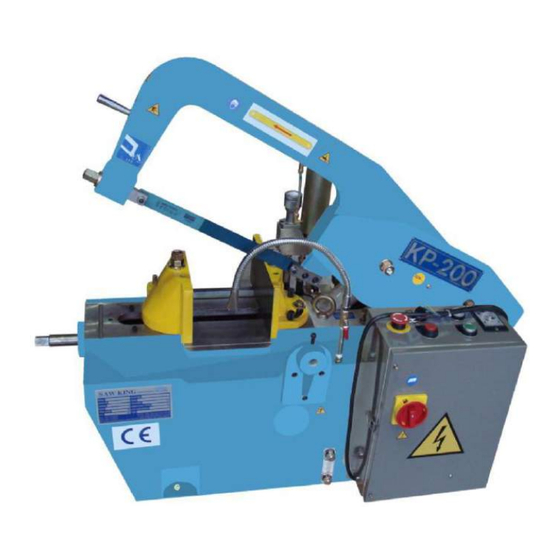
- Page 1 HYDRAULIC POWER HACK SAW MODEL : KP-200 OPERATION & MAINTENANCE MANUAL...
-
Page 2: Table Of Contents
1-3. Marking of Oil Replenishing Point................... 3-4 Chapter 2. Structure and Appearance of Machine 2-1. Performance and Function...................... 5-6 2-2. KP-200 Layout Drawing ......................7-8 2-3. Layout of Operator ........................9 2-4. Hazardous Location ......................10-11 2-5. Protective Device ........................ 12-13 Chapter 3. - Page 3 5-4. Balance Bar/Pressure Bar ......................26 5-5. Installation of Saw Blade ......................27 5-6. Precautions of POWER ON and POWER OFF ..............28-29 5-7. Controlling Units ......................... 30-31 Chapter 6. Adjustment of Instructions 6-1. Adjustment of Pressure ......................32 6-2. Adjustment of Vice Jaw (Front and Rear) ................33 6-3.
- Page 4 Chapter 10. Maintenance Table, daily, weekly, monthly, quarterly, and biyearly 10-1. Daily Check ..........................51 10-2. Weekly Check ......................... 51 10-3. Monthly Check ........................51 10-4. Quarterly Check ........................51 10-5. Biyearly Check ........................52 Chapter 11. Disposal of Waste, Fire Fighting 11-1.
- Page 5 Chapter 14. Circuit 14-1. Model: KP-200, Circuit ...................... 69-70 Chapter 15. Parts Dismantling Drawing 15-1. Model: KP-200, Machine Body Assembly ................. 71-73 15-2. Model: KP-200, Vise Assembly ..................74-75 15-3. Model: KP-200, Saw Frame Assembly ................76-78 15-4. Model: KP-200, Cyclinder Assembly ................. 79-81 15-5.
-
Page 6: Operation Preface
Operation Preface This manual is for speedy hydraulic sawing machine, which should be kept in place with easy reach of operators, and which covers safety instruction, delivery, installation, operation, etc., please read this manual carefully before operation and procedure so as to achieve the purposes of safety, promptness, and efficiency. -
Page 7: Chapter 1. Safety Instruction
Chapter 1. Safety Instruction This instruction must be carefully read and abided by installation undertakers, operators, and maintenance technicians. All hazardous locations of the machine are labeled with precaution marks, which shall not be removed in any event to ensure the safety of operator and normal running of machine. There are three sorts of caution marks as followings: Hazardous to the life or may cause severe injury of operator Medium injury such as cut or hit to operator... -
Page 8: Safety Instruction During Operating
1-2. Safety Instruction during Operating 1. When activating the machine, the saw blade must be placed around 20mm above the treated object to avoid breaking of saw blade. 2. When activating the machine, hands or any objects shall not be placed on any moving units of machine. 3. -
Page 9: Marking Of Oil Replenishing Point
1-3. Marking of Oil Replenishing Point KP-200:... - Page 10 KP-200 Oiling point/method/period ITEM REPLENISHING POINT OILING OILING METHOD PERIOD Bearings inside the chin Check Injecting lubrication oil by pushing injecting gun by 5 Everyday times, avoid spilling and clean it if any Between main gear and Check Injecting lubrication oil by pushing injecting gun by 7...
-
Page 11: Chapter 2. Structure And Appearance Of Machine
Chapter 2. Structure and Appearance of Machine 2-1. Performance and Function 2-1-1. Specification MODEL UNIT KP-200 CUTTING CAPACITY ● CUTTING CAPACITY ▀(H*W) 190*190 MAX. CUTTING DEGREE/DIA. N。/mm 45。/90 DISTANCE OF STROKE STROKES PER. MIN. times 105 . 125 BLADE SIZE 350*32*1.6*8.3... - Page 12 2-1-2. KP-200 Dimensions 1. Dimensions of various sections (scale: mm) 640 840 65 535 330 80 415 1200 355 380 995 995 425 565 440 300 350 2. Dimensions of Material Rack (scale: mm) 300 380 320 265 370 290...
-
Page 13: Kp-200 Layout Drawing
2-2. KP-200 Layout Drawing... - Page 14 ITEM NAME ITEM NAME Saw Frame Safety Switch Handle of Saw Frame Electric Box Handle of Vice Jaw Protection Cover of Side Belt Wheel Right Side Cover Slider Left Side Cover Timer of Saw Frame Height Protection Cover of Belt Wheel Saw Blade Lift Ring Measuring Bar of Sawing Length...
-
Page 15: Layout Of Operator
2-3. Layout of Operator KP-200 Scale: mm... -
Page 16: Hazardous Location
2-4. Hazardous Location 2-4-1. KP-200 Layout of Hazardous Location... - Page 17 2-4-2. Hazardous Solution KP-200: ITEM Hazardous Location Dangers Solution Handle in front of saw Hit on worker With caution mark frame Passage not allowed Saw blade Cutting With caution mark Clip handle With caution mark Running belt/wheel Clothes, hair drawn in...
-
Page 18: Protective Device
2-5. Protective device 2-5-1. Instruction of Danger Release as Hydraulic System Clipping Persons/Power Breaking Because this machine adopts passive mechanical hydraulic system, hence, when clipping, promptly turn the adjusting knob on the above to “0” to discharge the pressure, then the clipped person can be released, as following illustration: Protective cover (shield) of big belt wheel... - Page 19 Instruction of protective cover (shield) of big belt wheel: Item Application When to dismantle Auxiliary inner shield To prevent hands injury of person Do not dismantle Inner shield To prevent hands/hair/clothes from Do not dismantle pulling in Fixing screw of inner shield To fix the inner shield Do not dismantle Support screw of main...
-
Page 20: Chapter 3. Lift And Transportation Of Machine
Chapter 3. Lift and Transportation of Machine The following conditions must be read carefully before machine transporting: a. Operators of crane or fork lift must be qualified with licenses. b. The hook must be placed on the gravity center of machine. c. - Page 21 3-1-2. Fork Lift and Delivery Fork lift capacity must be >1 ton (2200 lbs). a. There must not be any obstacles/barriers along the moving path, speed must be slow, ensure no unstable or sliding situations. b. Worker must keep away from the machine at least 2 meters. c.
-
Page 22: Wooden Package For Exporting
3-2. Wooden Package for Exporting Notices of Unpacking: a. Check the appearance of wooden crate carefully. b. Carefully unpack the wooden crate without damaging parts and machine. c. Pay attention to nail, which must be disposed of properly to avoid environmental pollution. d. - Page 23 4-1-2. Installation Base and Parts A firm and stable base must require the following approaches and conditions a. Base area must comply with the base dimension of machine. b. Only qualified architecture can ensure the construction of firm base. c. Base must not locate on damping, oiling, and water-leaking area. d.
- Page 24 (Scale : mm) ITEM MODEL KP-200 100 450 645 25 280 330 M16*2.0 4-1-4. Power Supply(Power , Grounding and Requirement of Power Supply at the User’s End) a. AC Voltage : 3 phase AC220V or 380V or 400V or 415V ±10 % (Use transformer if necessary) b.
- Page 25 l. Frequency 0,99 to 1,01 of nominal frequency continuously;0,98 to 1,02 short time. m. Harmonics Harmonic distortion not exceeding 10 % of the total r.m.s. voltage between live conductors for the sum of the 2 through to the 5 harmonic. n.
- Page 26 4-1-5. Level Adjustment of Machine Using 4 sets of M16*20 bolts and nuts, plus 4 pieces of hard material underneath the machine base to adjust level. a. Level instrument shall be placed according to following drawing: b. Required tool and cautions as follows: 1.
-
Page 27: Maximum Space For Installation
4-2. Maximum Space for Installation Scale: mm The separation distance shall be determined by the length of treated objects. -
Page 28: Testing Procedure
Cutting liquid shall lie between the maximum and minimum levels, shown as following figure: MODEL Oil Volume (L) KP-200 g. In the case of using cooling water, the ratio of oil against waster shall be 1:20. h. Ensure all safety devices on right location, all switches must be “off”. - Page 29 4-3-2. Testing Confine 1. Test of Main Motor Turn on the power, power lamp lighting, press “START” button, ensure the rotation being the same direction with the above figure, turn off the power and change the two power cables mutually, otherwise. 2.
-
Page 30: Chapter 5. Operating Instructions
4. STOP/UP: STOP : a. To press this button to stop the main motor (stop the sawing action). b . Pressing “STOP” button of KP-200 will stop the lift the saw frame (inching lift) 5. TIMER: a. Timer is designed to control the lifting height of saw bar after sawing, scale: second. -
Page 31: Sawing Speed (Stroke/Min)
SAFETY SWITCH ON: a. When turning right to 90 degree, the machine is powered. b. When turning to ON, the manual must be read carefully. c. When turning to ON, the electric box cannot be opened. 7. EMERGENCY: a. This is for emergency button, when pressed, the power supply will be completely shut off. -
Page 32: Balance Bar/Pressure Bar
5-4. Balance Bar/Pressure Bar The function of balance bar is for short objects (I.E. the length of sawed object is shorter than half of vise jaw) shown as (B) in below figure, fix the balance bar to the back of front vise jaw, adjust the round head screw of rear vise jaw, make front and back vise jaw parallel to the sawed object. -
Page 33: Installation Of Saw Blade
5-5. Installation of Saw Blade The installation of saw blade will concern the machine precision, the operator’s safety and the life of machine. The operator has to study and follow the following indication in order to use this machine efficiently, safely. The saw blade needs to be replaced under following conditions: a. -
Page 34: Precautions Of Power On And Power Off
5-6. Precautions of POWER ON and POWER OFF 5-6-1. Inspection before POWER ON Only qualified workers can open electric box for operation or maintenance of parts, motor, or transformer. Other unauthorized persons are not allowed to open to avoid electric shock. Precaution before Powering Checking sections Key items... - Page 35 5-6-2. Checking Points after Power On Checking point Checking item Method Main motor abnormal noise overheating hand touch Water pumping motor 1. abnormal noise obstacle drawn in Hydraulic motor abnormal noise overheating hand touch Hydraulic pipe oil leaking damage of pipe 5-6-3.
-
Page 36: Controlling Units
3. Turn OFF to stop the power supply. 1. Stop the main motor under normal operation (stop sawing). 2. STOP BUTTON of KP-200 has stopping and lifting function (lifting is done by inching). 1. Start the main motor (start sawing). - Page 37 1. The lamp is on to indicate power alive. 2. The lamp is off to indicate power not alive. 1. Press this button to stop all power and operation. 2. For emergency use only. 3. Press this button to ensure safety after job finishing. 1.
-
Page 38: Chapter 6. Adjustment Of Instructions
Chapter 6. Adjustment of Instructions 6-1. Adjustment of Pressure The adjustment of pressure is determined as following drawing plus the table above: a. The pressure value must be set to “0” after work, to avoid incorrect pressure for next job, incorrect pressure may cause danger. -
Page 39: Adjustment Of Vice Jaw (Front And Rear)
6-2. Adjustment of Vice Jaw (Front and Rear) For wider sectional use of saw blade, the vice jaw can be adjusted to move to proper locations for such applications as following illustrations” Usage for back part of blade: Use the jaw locating pin to fix the back part of vise jaw to the table, then use the vise handle to fix sawed objects, shown as the following drawing: ①Take up the locating pin from the front vice jaw ②Insert the locating pin into the rear vice jaw... -
Page 40: Adjustment Of Sawing Angle
ITEM NAME ITEM NAME Auxiliary Fixed Bolt Adjusting Nut Locating Pin Rear Fixed Vice Jaw Fixed Nut Saw Blade Maximum Sawing Diameter under Angle 45 MODEL Max. Dia.(mm) KP-200... -
Page 41: Tension Adjustment And Selection Of Saw Blade
MODEL TENSION VALUE KP-200 1.8 T/cm² Commonly, rare plants have a tension meter, just use #21 wrench to turn the blade tension adjusting nut with 1 or 1&1/2 rotation counter-clockwise to meet the required tension values. - Page 42 6-4-2. Blade Reference for Sawing on L, H, Pipe Shapes The teeth of blade will affect the machine life, precision, damage of blade, efficiency, please refer to the following instruction: a. Sawing on metal of H shape b. Sawing on metal of L shape c.
- Page 43 6-4-3. Sawing Time Has Relationship with Material Features and Diameters of Sawed Object. The following figure is the relationship illustration: Economic sawing velocity Profile Diameter Sawing time (Minute)
-
Page 44: Chapter 7. Troubleshooting Guide
Chapter 7. Troubleshooting Guide 7-1. Inspection Standard of Machine SAW KING INDUSTRIAL CO., LTD. INSPECTION STANDARD Item Inspection item Inspection method Illustration Permissible Reading error (mm) (mm) Flatness A front and Place precision level on 0.20/m of the rear the table, at least three table direction points such as the... - Page 45 SAW KING INDUSTRIAL CO., LTD. INSPECTION STANDARD Item Inspection item Inspection method Illustration Permissible Reading error (mm) (mm) The perpendicularity Test indicator be put on Each 100 between the the test plate(2) which is 0.10 clamping surface mounted on the bow (fixing surface) of frame, and be contacted work clamp and the...
-
Page 46: Guidelines Of Common Solutions
7-2. Guidelines of Common Solutions Problems Root Causes Solutions Sawing not straight 1. attrition of saw blade 1. replace new blade 2. insufficient blade tension 2. adjust to required tension 3. too loose saw frame against 3. adjust to the gap to 0.03mm between saw slider frame against slider 4. -
Page 47: Chapter 8. Safety Instruction
Chapter 8. Safety Instruction 8-1. Safety Instruction before Maintenance WARNING : Isolating the main power to machine before main maintenance Before maintenance, this instruction manual must be read carefully and fully understood. The caution stand/mark must be placed before the working site. -
Page 48: Chapter 9. Lubrication Oil Maintenance
Chapter 9. Lubrication Oil Maintenance Preventing fluids (hydraulic oil/metalfluid) spillage onto the surrounding area and thus creating slipping hazard. 9-1. Maintenance of Saw Frame and Chin Head As drawing: ○ The bearing inside the chin head, ○ Contact section between big gear and saw frame, ○ Contact section between saw frame and outer slider(the safety switch must be turned off for safety) Following table displays maintenance methods and cycles: ITEM Maintenance Section... -
Page 49: Replenishment And Replacement Of Hydraulic Oil
(3 months) to avoid damage to the machine and parts; specification oil is MOBIL DTE Light 32 Reference Table: Model Replacing Cycle Oil Specification Volume (L) KP-200 Every 3 months MOBIL DTE Light 32 1.4 L... - Page 50 Right Side Protection Cover Table (1) Table (2) ITEM NAME Model KP-200 Stopper Waste oil tank 1.8L Waste oil tank 1. Firstly prepare a proper waste oil tank, reference as table (2) ○ 2. Release the stopper with proper wrench , before removing the stopper, put a container below to avoid ○...
- Page 51 Use a clean oil tank with proper capacity, refer to following table: 1. Models and Volume Model Tank Volume KP-200 1.8 L 2. Specification of oil: MOBIL DTE Light 32 ○ 3. As following drawing (1), press the saw frame to the bottom and adjust the pressure between scale○...
-
Page 52: Maintenance Of Vice Jaw
5. Pouring in the clean hydraulic oil into oil tank 6. Never replenish in excess of the high position of oil 7. Life the saw frame between angles from 20 to 30 , then repeated the actions of pushing down and lifting up till the oil level reaches the low position of oil, again to replenish the oil up to the high position of oil 8. - Page 53 9-3-2. Maintenance of Fixed Screw of Vice Fixed Nut Adjusting Nut Adjusting Nut Moving Vice Inserting Pin Spread grease once per 6 months Fixed Vice Maintenance Cycle: 6 months, Oil Specification - MOBILITH AW3 1. As friction of the section, apply oil to lubricate at regular interval 2.
-
Page 54: Maintenance Of Adjusting Screw Of Saw Blade Tension
9-4. Maintenance of Adjusting Screw of Saw Blade Tension ○ Saw Blade Saw Frame ⑤ ⑥ ○ Adjusting Screw of Saw Blade ⑦ Tension ○ Adjusting Nut ⑧ ② Washer Tension adjustment of saw blade will affect the sawing precision, please maintain the parts according to following steps: a. -
Page 55: Replacement Of Cutting Liquid
9-5. Replacement of Cutting Liquid Cutting liquid may affect the precision, lift of blade, which must be replaced periodically as following steps: a. Turn off safety switch and place a caution mark to avoid danger before maintenance ○ b. Remove protection covers , and put them in a clear place, remove dirt and dust thereof, as following illustration ○... - Page 56 Use a cross driver to restore the cable, fix the isolation chip, to avoid damping m. Put on the right and left protection covers and tighten them up, replenish in proper volume of cutting liquid as following table: Model KP-200 Volume 17 L Mixing ratio of cutting liquid (Mobilcut 102) against water 1:20 n.
-
Page 57: Chapter 10. Maintenance Table, Daily, Weekly, Monthly, Quarterly, And Biyearly
Chapter 10. Maintenance Table, daily, weekly, monthly, quarterly, and biyearly 10-1. Daily Check ITEM Checked Section Key Point Blade tension Adjust to proper tension of blade (refer to manual) Oil tank Replenish MOBIL DTE Light 32# hydraulic oil properly Level of cutting liquid Avoid insufficient level (may affect sawing) Avoid successive level (may cause slipping and falling) Platform... -
Page 58: Biyearly Check
10-5. Biyearly Check ITEM Checked Section Key Point Vice Jaw Distortion, wear and tear Platform Distortion, wear and tear a. Bearing of chin a. Loose, wear and tear b. Bearing of roller b. Loose, wear and tear c. Roller and sliding trough c. -
Page 59: Dismantling And Scrapping
11-3. Dismantling and Scrapping WARNING: Before dismantling the machine, disconnect all energy sources carefully. (1) Dismantling of Electrical Systems Before disconnect the cables from the power cabinet, please confirm first that all switches have been closed. The removing of power cabinet and every connecting cable. (2) Dismantling of Mechanical Components Before dismantling the mechanical body, please clean the whole structure in order to dismantle conveniently. -
Page 60: Chapter 12. Maintenance And Repair Instructions
Chapter 12. Maintenance and Repair Instructions Warning: “Turn off power or push E-STOP button before maintenance” While using machines, the operational manual must be read carefully and thoroughly. Machine must be maintained properly periodically. In the event of malfunction, abnormality, please refer to following table for trouble shooting. - Page 61 ITEM 1 b 1 Malfunction Insufficient Sawing Pressure Cause b. Parts malfunctions inside the cylinder Trouble b 1 Bad sliding as illustration shooting Sliding Section 1 Small Piston Axel 2 Big Piston Bar 3 Spring Head of Tube Fixed Screw of Big Pressed Spring of 6 Spring Tube Piston Bar...
-
Page 62: Noise In Chin Head
ITEM 1 c Malfunction Insufficient Sawing Pressure Cause c. Fatigue spring of pressure adjustment Trouble shooting Pressure Adjusting 2 Scale 3 Pressure Adjusting Spring Knob Pressure Adjusting Steel Ball Ring of Pressure Adjusting Screw Washer Spring Steel Ball/Sphere 8 Steel Ball 9 High Pressure Hose Contact ○... - Page 63 ITEM 2 d Malfunction Noise in Chin Head Cause d. Excessive gaps between saw frame and slider, or saw frame and chin head Trouble shooting d. Use a #23 fixed wrench and a #23 hex wrench to micro-adjust the gap, around 0.03mm, as the illustration below: Gap around 0.03mm Gap around 0.03mm...
-
Page 64: Insufficient Lifting Height Of Saw Frame After Sawing Job
12-3. Insufficient Lifting Height of Saw Frame after Sawing Job ITEM 3 a Malfunction Insufficient lifting height of saw frame after sawing job Cause a. Fatigue spring of cylinder Trouble shooting a. 1. Refer to ITEM 1 b 1 to replace the fatigue spring 2. -
Page 65: Tilt Under Proper Pressure
Damaged or deteriorated O ring on the top or bottom of cylinder Trouble shooting c. Check the O rings on top or bottom covers, replace the ring, type: (KP-200) G105, ensure the O ring placed into the trough without outstanding part Remark... - Page 66 3 C Clasp RTW-43 4 Dust Seal 36*28*6 5 O Ring P-22A 6 Oil Seal UPH 28*43*10 7 O Ring KP-200 /G105 Remark d. Repaired by qualified technician, dismantled parts must be placed in clean place. Replenish oil after replacement, refer the manual instruction...
- Page 67 ITEM 5 e Malfunction Oil level of pressure adjusting value decreases abnormally Cause e. Magnetic valve or O ring between which and cylinder deteriorated or damaged Trouble shooting e. Replace O ring as following illustration: 1 Spring Tube of 2 Base of 3 Fixing Bolt of Magnetic Valve Magnetic Valve...
-
Page 68: Chapter 13. Maintenance/Repair Instructions For Electric Apparatus
Chapter 13. Maintenance/Repair Instructions for Electric Apparatus Warning: “Turn off power or push E-STOP button before maintenance” The electric parts and apparatus inside the saw machine are with CE standard and approval, and certified safety and quality. Using frequency, history, operation, and plant environment may affect the precision and life span of such machines, please refer to following notices and instructions for proper maintenance. -
Page 69: Not Start While Pressing "Start" Button
13-2. Not Start while Pressing “START” Button ITEM 2 Malfunction Not start while pressing “START” button Cause a. Damaged “START” button b. Damaged fuse on main motor c. Lack of phase on motor, bad connection on either cable among three phases d. -
Page 70: Motor Not Stops After Sawing Completion
13-4. Motor Not Stops after Sawing Completion ITEM 4 Malfunction Motor not stops after sawing completion Cause a. Damaged prompt switch b. Any dirt/dust, object in the prompt switch, or its connection spot moved Trouble shooting Check prompt switch, or replace it if necessary Notice the proper connection and location, ensure to adjust the lifting height of saw frame properly, as illustration: Adjusting spot of prompt... -
Page 71: Saw Frame Not Rises Rapidly After Sawing Completion
13-5. Saw Frame Not Rises Rapidly after Sawing Completion ITEM 5 Malfunction Saw frame not rises rapidly after sawing completion Cause Damaged coil inside the magnetic valve Damaged timer Trouble shooting a. Check if there is any vibration or magnetic noise while touching the cylinder coil and pressing “STOP UP”... -
Page 72: Cooling Water Or Cutting Liquid Not Supplied
13-6. Cooling Water or Cutting Liquid Not Supplied ITEM 6 Malfunction Cooling water or cutting liquid not supplied Cause a. Malfunction of cooling water motor b. Adverse rotation of cooling water motor c. Failure or bad connections of cables Trouble shooting a. -
Page 73: Electricity Not Supplied
13-8. Electricity Not Supplied ITEM 8 Malfunction Electricity not supplied Cause Damaged fuse Malfunction of Safety Switch Damaged prompt switch of belt wheel cover, or bad connection of cover Damaged control switch Trouble a. Check fuse and replace it if necessary, notice the current and voltage shooting b. -
Page 74: No Sawing Pressure, Saw Frame Lifting
13-11. No Sawing Pressure, Saw Frame Lifting ITEM 11 Malfunction No sawing pressure, saw frame lifting Cause a. Damaged timer activates the magnetic valve to “on” b. STOP/UP button damaged Trouble a. Replace new timer with normal function shooting b. Check the normality of STOP/UP switch, or replace it if necessary Remark 1. -
Page 77: Chapter 15. Parts Dismantling Drawing
Chapter 15. Parts Dismantling Drawing The following drawings are for prompt identifications on spare parts and maintenance/repair reference without confusion and misunderstanding, which include item, part no., name, specification, kindly contact local dealer/producer for prompt service. - Page 78 Model: KP-200 Title: MACHINE BODY ASSEMBLY Drawing No: M-092001 ITEM PART NO. DESCRIPTION SPECIFICATION Q’TY N-10-04 M6*1.0 P-25137 PULLEY SIDE COVER N-10-02 M4*0.5 P-25119 MICRO SWITCH HOLDER LM-18-02 MICRO SWITCH TM1703 W-20-04 WASHER Ø 6*12*0.6 S-04-03 HEX HEAD CAP SCREW M6*1.0*12...
- Page 79 P-20133-2 COVER S-09-01 HEX HEAD CAP SCREW M16*2.0*45 P-11-01 TWO-HEAD PIPE 1/4”PT*1/4”PT*30 J-15-01 WIRE MESH 220*120 HC-40-01 FIXED RING Ø 19mm...
-
Page 80: Model: Kp-200, Vise Assembly
15-2 Model: KP-200 Title: Vise Assembly Drawing No.: M-092002 8-2:... - Page 81 Model: KP-200 Title: VISE ASSEMBLY Drawing No.: M-092002 ITEM PART NO. DESCRIPTION SPECIFICATION Q’TY P-25130-2 TURN HANDLE P-25130-1 TURN HANDLE SCREW S-08-01 HEX HEAD CAP SCREW M14*2.0*70 W-20-08 WASHER Ø 14.5 P-25127 S-07-01 HEX SOCKET CAP SCREW M12*1.75*45 P-25135 WASHER Ø...
- Page 83 Model: KP-200 Title: SAW FRAME ASSEMBLY Drawing No.: M-092003 ITEM PART NO. DESCRIPTION SPECIFICATION Q’TY P-20211 GEAR SHAFT BR-29-32 ROLLER BEARING RNA-6904 BR-29-24 BALL BEARING 6010Z GR-70-01 GREASE NIPPLE GR-K 1/8”PT P-20202 SAW FRAME HEAD BR-29-23 BALL BEARING 6009ZZ BR-29-07...
- Page 84 P-20214 ECCENTRIC SHAFT BEARING BR-29-16 BALL BEARING 6207NR P-20208 GEAR ROLLER SHAFT P-20210 GEAR P-20209 ROLLER SHAFT BR-29-02 BALL BEARING 6203 P-20206-2 BEARING SPACER P-25136-2 BLADE SCREW P-25205-3 BLADE WASHER HC-22-01 SAW BLADE 350*32*1.6*8.1 P-20204-1 BLADE ADJUST PLATE NR-11-05 STAINLESS STEEL NUT M8*1.25 S-05-11 HEX SOCKET CAP SCREW...
- Page 86 Model: KP-200 Title: CYCLINDER ASSEMBLY Drawing No.: M-092004 ITEM PART NO. DESCRIPTION SPECIFICATIO Q’TY P-20327 SMALL PISTON TOUCH SHAFT S-0404 HEX SOCKET CAP SCREW M6*1.0*20 S-10-01 HEX SOCKET CAP SCREW M6*1.0*10 P-20312 SLEEVE P-20311 SPRING S-04-05 HEX SOCKET CAP SCREW M6*1.0*25...
- Page 87 AD-21-04 M8*1.25 W-20-05 WASHER Ø 8.5 AD-21-03 BRAND AD-8C-V-GEI-24V AD-21-02 INDUCTION COIL AD-8C-V-GEI-24V ASSEBBLY OF HIG PRRESSURE OIL PIPE CONNECTING PARTS SPECIFICATION OF OIL PIPE PIPE LENGTH (mm) CONNECTION OF ITEM 24 AND OUTSIDE OF PUMP BASE 3/8”HT CONNECTION OF ITEM 33 AND INSIDE OF PUMP BASE 3/8”HT...
-
Page 88: Model: Kp-200, Pressure Adjustable Assembly
15-5 Model: KP-200 Title: Pressure Adjustable Assembly Drawing No.: M-092005... - Page 89 Model: KP-200 Title: PRESSURE ADJUSTABLE ASSEMBLY Drawing No: M-092005 ITEM PART NO. DESCRIPTION SPECIFICATIO Q’TY OH-06-01 OIL HOSE 6*4.6*108 OB-60-01 “L” SQUARE ELBOW 1/8”PT*5.5 P-25318 OIL TANK OC-62-01 FLUG 1/2”HT*32*6 OH-06-02 OIL HOSE 6*4.6*110 S-04-04 HEX SOCKET CAP SCREW M6*1.2*2.0...
-
Page 90: Model: Kp-200, Roller Stand Assembly
15-6 Model: KP-200 Title: Materials Rack Assembly Drawing No.: M-092006 Model: KP-200 Title: MATERIALS RACK ASSEMBLY Drawing No.: M-092006 ITEM PART NO. DESCRIPTION SPECIFICATIO Q’TY S-05-07 HEX HEAD CAP SCREW M8*1.25*40 SW-30-05 SPRING WASHER Ø 8.5 P-20407 MATERIALS RACK P-25406-2... -
Page 91: Model: Kp-200, Measure Bar Assembly
15-7 Model: KP-200 Title: Measure Bar Assembly Drawing No.: M-092007 Model: KP-200 Title: MEASURE BAR ASSEMBLY Drawing No.: M-092007 ITEM PART NO. DESCRIPTION SPECIFICATIO Q’TY P-20404 W-20-08 WASHER Ø 14.5 P-20405 LENGH FIXED ROD N-10-05 M8*1.25 S-05-05 HEX HEAD CAP SCREW M8*1.25*30... - Page 92 EC Declaration of Conformity The supplier (responsible party), Excel Machine Tools Ltd, declares that the product described, Hydraulic Power Hacksaw Model Serial Number Conforms to the following Directives: Machinery Directive 2006/42/EC. Electromagnetic Compatibility Directive 2004/108/EC Low voltage Directive 2006/95/EC. Using the following Standards:...
Need help?
Do you have a question about the KP-200 and is the answer not in the manual?
Questions and answers