uAvionix AV-30-E Installation Manual
Hide thumbs
Also See for AV-30-E:
- Pilot's manual (101 pages) ,
- Installation manual (54 pages) ,
- Service bulletin (37 pages)
Table of Contents
Advertisement
Quick Links
Advertisement
Table of Contents

Subscribe to Our Youtube Channel
Related Manuals for uAvionix AV-30-E


Summary of Contents for uAvionix AV-30-E
- Page 1 AV-30-E Installation Manual UAV-1004234-001 Rev H...
- Page 2 retained.
-
Page 3: Revision History
Revised AV-Mag installation procedure to eliminate earth magnetic field and simplification for AV-Mag hardware that can measure its own 2/28/2023 installation angle. Updated AV-Link for latest version (0.3.0) and new IP (192.168.5.1). UAV-1004234-001, AV-30-E Installation Manual Rev H... - Page 4 Updated 13.1.6 to indicate units match IAS UNITS. Updated 13.1.7 to indicate IAS UNITS applies to IAS V-Speeds, IAS TRIM, displayed GS, and displayed IAS. Clarified parallel tailBeaconX behavior in section 11.2 Update 11.6 to describe screw depth gauge UAV-1004234-001, AV-30-E Installation Manual Rev H...
-
Page 5: Warnings / Disclaimers
Warnings / Disclaimers All device operational procedures must be learned on the ground. uAvionix is not liable for damages arising from the use or misuse of this product. This equipment is classified by the United States Department of Commerce's Bureau of Industry and Security (BIS) as Export Control Classification Number (ECCN) 7A994. -
Page 6: Limited Warranty
Limited Warranty uAvionix products are warranted to be free from defects in material and workmanship for two years from the installation of AV-30-E on the aircraft. For the duration of the warranty period, uAvionix, at its sole option, will repair or replace any product which fails in normal use. Such... -
Page 7: Table Of Contents
Transponder Control (Optional) ........29 9.2.3 AV-Link Interface (Optional) ......... 29 9.2.4 Autopilot Interfaces (Optional) ........29 9.3 Internal Battery Operation ............30 9.3.1 General ................ 30 10 Equipment Installation ..............31 10.1 Overview ................31 UAV-1004234-001, AV-30-E Installation Manual Rev H... - Page 8 11.2.1 Transponder Control ............ 54 11.2.2 Transponder Testing with AV-30 ........54 11.3 AV-Mag External Magnetometer ........... 54 11.3.1 Magnetometer Overview ..........54 11.3.2 System Function ............55 11.3.3 AV-Mag Specifications ..........56 11.3.4 AV-Mag Software ............57 UAV-1004234-001, AV-30-E Installation Manual Rev H...
- Page 9 11.4.2 AV-APA Specifications ..........70 11.4.3 AV-APA Installation Overview ........73 11.4.4 AV-APA Installation Materials and Tools ...... 73 11.4.5 Configure the AV-30-E for the AV-APA ......74 11.4.6 AV-APA Wiring and Autopilot Configuration ....76 11.4.7 Ground Checkout ............78 11.5 Digital Autopilots ..............
- Page 10 13.2.11 AV-APA Checkout ............. 125 13.2.12 EMC Checkout ............126 14 Troubleshooting ................ 128 15 Serial Interface Specification ............ 130 16 Field Update Capability ............. 131 17 Appendix A: Example Wiring Schematics ......... 132 UAV-1004234-001, AV-30-E Installation Manual Rev H...
-
Page 11: Introduction
Minimum steady flight velocity while still controllable. The bottom end of the ASI green arc. Maximum flap extended velocity. The top end of the ASI white arc. Maximum normal operating velocity. The top end of the ASI green arc. UAV-1004234-001, AV-30-E Installation Manual Rev H... - Page 12 Maximum velocity in smooth air (never exceed). The red line at the top end of the ASI yellow arc. Minimum control airspeed with the critical engine inoperative Speed for best rate of climb OEI (single engine) UAV-1004234-001, AV-30-E Installation Manual Rev H...
-
Page 13: System Information
AV-30 multi-mode instrument. 6.1 System Description The uAvionix AV-30 is a fully digital multi-mode instrument that mounts in the legacy 3-1/8” round instrument panel. It can be field configured as either an Attitude Indicator (AI), a Directional Gyro (DG) indicator or Multi-Function Display (MFD). -
Page 14: System Functions
An internal, rechargeable battery allows for operation for a nominal 1 hour in the event of aircraft power loss in flight and 30 minutes minimum under all temperature conditions. See UAV-1004233-001, AV-30-E, Pilot’s Guide for additional details. 6.2 System Functions Primary Functions:... - Page 15 Audio and Visual Alerting Functions: - AoA Alerting - G Limit Alerting - Excessive Roll Alerting - Set Altitude Alerting - Carbon Monoxide Alert with AV-Link and Sentry Misc. Functions: - Internal Battery Operation UAV-1004234-001, AV-30-E Installation Manual Rev H...
- Page 16 Altitude 25,000 Feet (maximum) Optical Characteristics 3” Circular Diagonal Size Contrast Ratio (Typical) Brightness (Typical) 1000 cd/m Viewing Angle Left/Right 60° Viewing Angle Up 45° Viewing Angle Down 10° Backlight Lifetime (Typical) 50,000 Hours UAV-1004234-001, AV-30-E Installation Manual Rev H...
- Page 17 UAV-1004234-001, AV-30-E Installation Manual Rev H...
-
Page 18: Design Standards
For aircraft capable of acrobatic flight, the AoA indication may become unreliable for operation in inverted flight and maneuvers exceeding ±8 G. For panels with more than 15 degrees of panel tilt, the AoA indication may not indicate correctly. UAV-1004234-001, AV-30-E Installation Manual Rev H... -
Page 19: Applicable Performance Standards
Direction instrument, Magnetic (Gyroscopically Stabilized) ASTM F3011-13 Standard Specification for Performance of Angle of Attack System RTCA DO-347 Certification Test Guidance for Small and Medium Size Medium Sized Rechargeable Lithium Batteries and Battery Systems UAV-1004234-001, AV-30-E Installation Manual Rev H... -
Page 20: Installation Locations & Operating Modes
• Unit locked as a dedicated Direction Indicator (DG Mode); can be toggled between DG and MFD mode by the pilot. • Unit unlocked; can be toggled between AI, DG, and MFD mode by the pilot. UAV-1004234-001, AV-30-E Installation Manual Rev H... - Page 21 If the functionality is not locked, pressing and holding the rotary knob will toggle between AI, DG, and MFD modes. UAV-1004234-001, AV-30-E Installation Manual Rev H...
-
Page 22: Functionality And Required Interfaces
Various interfaces are optional as indicated in the following diagrams. Do not plug the pitot and static lines. Figure 3 – AV-30 Aircraft Systems Interfaces – AI Mode UAV-1004234-001, AV-30-E Installation Manual Rev H... -
Page 23: Feature Matrix
Pitot / Static ✓ Direction Arc (GPS) GPS Navigator ✓ Direction HSI (DG) Pitot / Static ✓ Direction HSI (GPS) GPS Navigator Supplemental Data Overlays – Pilot Configurable (Textual or Graphical) UAV-1004234-001, AV-30-E Installation Manual Rev H... -
Page 24: Power Input (Required)
This architecture allows the unit to continue operation if external power fluctuates or is completely lost. Input range is compatible with both 12V and 24V aircraft. UAV-1004234-001, AV-30-E Installation Manual Rev H... -
Page 25: Pitot And Static Interfaces (Required)
This port connection is compatible with the Davtron P/N C307PS (not supplied). This is a differential two-wire current source based on the Analog Devices AD590KH component and supplies a current that corresponds to the ambient temperature. UAV-1004234-001, AV-30-E Installation Manual Rev H... -
Page 26: Audio Output (Optional)
9.2.5 Navigation Interface (Optional) The Navigation Interface is an optional RS-232 serial interface that can be connected to one of the following: • “Aviation” output provided by most panel mounted GPS units UAV-1004234-001, AV-30-E Installation Manual Rev H... - Page 27 Aviation and NMEA GPS may be connected in parallel between multiple AV-30 units and is supported in both AI and DG modes. The supported protocols are contained in Section 15 - Serial Interface Specification. UAV-1004234-001, AV-30-E Installation Manual Rev H...
-
Page 28: Internal Magnetometer (Optional)
The installation of the AV-Mag magnetometer is sensitive to orientation and tilt so the installation instructions and measurements must be followed carefully. The magnetometer also requires calibration before use. The AV-Mag receives power from the AV-30-E and will run UAV-1004234-001, AV-30-E Installation Manual Rev H... -
Page 29: Transponder Control (Optional)
Transponder operations will be unavailable during a power loss. 9.2.3 AV-Link Interface (Optional) The AV-30-E has the option of being a traffic display using AV-Link as an integrated Wi-Fi bridge that allows for communication between AV- 30-E and Wi-Fi capable ADS-B receivers. The AV-30-E will display a separate MFD page with traffic when appropriate configured and connected to a supported receiver. -
Page 30: Internal Battery Operation
1. While AV-30-E is aligning, the unit will continue in battery mode if power is lost. Once aligned it will shut down. 2. If any button is pressed after power is lost, the AV-30-E will stay in battery mode. 3. If the AV-30-E senses airspeed or GPS groundspeed, it will stay in battery mode. -
Page 31: Equipment Installation
AV-Link Wi-Fi Bridge AV-Mag External (Optional) AV-Mag-E UAV-1006321-001 Magnetometer AV-APA Analog Port (Optional) AV-APA UAV-1006839-001 Adapter AV-HSI ARINC 429 (Optional) AV-HSI UAV-1007412-001 Adapter The AV-30-E Installation Kit includes the following: • 6-32 mounting screws UAV-1004234-001, AV-30-E Installation Manual Rev H... - Page 32 If your kit includes machined pins, a Daniels AFM8 crimp tool using a K13-1 positioner or equivalent M22520/2-01 tool should be used. If your installation kit includes the original stamped pins, a NorComp 180-701-170-000 hand crimper or equivalent should be used. UAV-1004234-001, AV-30-E Installation Manual Rev H...
-
Page 33: Non-Supplied Components
Entry should include instrument(s) being replaced (AI, DG, or both), or if the installation is being performed as a non-required instrument. Entry should also include a description of any optional connections made. Entry should include AV-Mag installation location, orientation, and attitude angles. UAV-1004234-001, AV-30-E Installation Manual Rev H... -
Page 34: Mechanical Drawing
The AV-30 is fastened to the instrument panel with four Stainless Steel 6-32 screws. The unit mounts from the rear of the instrument panel, with the screws being inserted from the front of the panel. UAV-1004234-001, AV-30-E Installation Manual Rev H... - Page 35 Using screws that are too short could lead to stripped mounting holes. Always use caution when tightening the mounting screws, if the screw feels like it is bottoming out, STOP, and correct the screw thread engagement. UAV-1004234-001, AV-30-E Installation Manual Rev H...
- Page 36 Place a mounting screw through the panel and feel the back surface of the tool where the screw should be. The screw can be flush with the tool surface or up to 0.5mm (0.020in) below UAV-1004234-001, AV-30-E Installation Manual Rev H...
- Page 37 Thread engagement = 6.35 – 2.29 = 4.06mm i. This screw may be used in the Bottom Mounting holes since 4.06mm < 4.2mm, but NOT in the top mounting holes as it is too long. UAV-1004234-001, AV-30-E Installation Manual Rev H...
- Page 38 Insert your reducing washer and screw and repeat the process from 1c above. Use caution when tightening the screw. Figure 9 - Bridging using back side of tool when working with enlarged holes and reducing washers. UAV-1004234-001, AV-30-E Installation Manual Rev H...
-
Page 39: Wiring Diagrams
Additional details on installation of accessories can be found in Section 11 Optional Equipment Installation. Use 22 or 24 AWG MIL-C-27500 or equivalent shielded wire unless other is specified in the installation drawings. AC 43.13-1B should be used for additional guidance where needed. UAV-1004234-001, AV-30-E Installation Manual Rev H... - Page 40 Figure 10 - Wiring Diagram – Required Connections UAV-1004234-001, AV-30-E Installation Manual Rev H...
- Page 41 Figure 11 - Wiring Diagram – Optional Connections 1 of 2 UAV-1004234-001, AV-30-E Installation Manual Rev H...
-
Page 42: Bonding Requirements
Figure 12 - Wiring Diagram – Optional Connections 2 of 2 10.8 Bonding Requirements The following figure shows the grounding requirements for the electrical connections. The two D-Sub screws are to be utilized for shield and ground strap connections. UAV-1004234-001, AV-30-E Installation Manual Rev H... - Page 43 The bond between the unit (measured at the D-sub screws) to the aircraft frame must be 2.5 milli-Ohms or less. D-SUB BACK-SHELL GROUND STRAP < 8” AIRCRAFT GROUND CABLE SHIELD DRAIN < 2.5” Figure 15 - Cable Shields and Ground Strap UAV-1004234-001, AV-30-E Installation Manual Rev H...
-
Page 44: Unit Pinout
Audio Alerts hi Audio L Output Audio Panel lo Aux Power Out Power AV-Mag / Auxiliary Power OAT Return Input White / Blue Probe Wire Software Update Harness or Serial 3 Output Third Party EFIS UAV-1004234-001, AV-30-E Installation Manual Rev H... -
Page 45: Optional Equipment Installation
AV-Link and AV-30, when paired with an ADS-B receiver, can display traffic information. This information is supplemental and for advisory use only. It cannot replace required equipment. 11.1.2 FCC ID Table 11-1 - FCC ID Model FCC ID AV-Link Contains 2AC7Z-ESPWROOM02U UAV-1004234-001, AV-30-E Installation Manual Rev H... -
Page 46: Av-Link Specifications
Operating temperature range -45°C to +70°C Maximum pressure altitude 35,000 ft Input voltage range 9 to 30.3 VDC 0.02A idle 14V current 0.025A typical 0.05A maximum 0.01A idle 28V current 0.0125A typical 0.025A maximum UAV-1004234-001, AV-30-E Installation Manual Rev H... -
Page 47: Av-Link Software
• Flat Screwdriver • 3/16” Nut Driver 11.1.6 Additional Required Equipment AV-Link is designed to interface with an existing AV-30 display. To take advantage of AV-Link the following equipment is required: • AV-30 3-1/8” Display UAV-1004234-001, AV-30-E Installation Manual Rev H... -
Page 48: Mounting
Do not attempt to remove the two [2] captive Jack Screws from the AV- Link housing. Attach AV-Link to the back of the AV-30 by inserting the unit into the DB-15 connector on the back of the AV-30. UAV-1004234-001, AV-30-E Installation Manual Rev H... - Page 49 Using a 3/16” nut driver, tighten the two [2] Jack Screws to 5 in-lbs. maximum. Do Not Overtighten! Reattach the original AV-30 Backshell Connector. Using a flat screwdriver, tighten the two [2] screws to 5 in-lbs. maximum. UAV-1004234-001, AV-30-E Installation Manual Rev H...
-
Page 50: Reinstallation In Instrument Panel
As shipped from the factory, the AV-Link will function in default mode and should not need customization. If it is necessary to change AV-Link settings or apply firmware updates, the AV-Link may be accessed through a web browser. UAV-1004234-001, AV-30-E Installation Manual Rev H... -
Page 51: Wi-Fi Firmware Update Page
The AV-Link can be returned to factory settings from the AV-30 installation menu. For example, if the WiFi password was set but forgotten, the factory reset will delete the password. AV-Link software version 0.2.39 or later is required to support factory reset. UAV-1004234-001, AV-30-E Installation Manual Rev H... - Page 52 To execute factory reset, go to the AV-30 installation menu item named “RESET AVLINK”, select YES, then press and hold the right button until “COMPLETE” appears. UAV-1004234-001, AV-30-E Installation Manual Rev H...
-
Page 53: Transponder (Tailbeaconx)
AV-30s according to Figure 21. Note that the tailBeaconX will only output GPS data when controlled by an AV-30. As diagramed in Figure 21, the top AV-30 will only receive GPS data if the bottom AV-30 is powered on and configured properly. UAV-1004234-001, AV-30-E Installation Manual Rev H... -
Page 54: Transponder Control
Figure 21 - Parallel tailBeaconX GPS Connections 11.2.1 Transponder Control Transponder controls are enabled by selecting “BEACON X” on the “SERIAL 2” installation menu. See AV-30-E Pilot’s Guide UAV-1004233- 001 for transponder control interface configuration. 11.2.2 Transponder Testing with AV-30 Ground test mode may be initiated from the AV-30 via the following: •... -
Page 55: System Function
11.3.2 System Function The AV-Mag, when paired with an AV-30, can provide consistent and accurate heading. The AV-Mag is an aiding device and does not provide full slaving to the AV-30. UAV-1004234-001, AV-30-E Installation Manual Rev H... -
Page 56: Av-Mag Specifications
1.4 oz (40.0 grams) Operating temperature range -40°C to +70°C Maximum pressure altitude 35,000 ft 7 VDC typical (from AV-30 Input voltage range auxiliary power output) 7V current 12 mA typical Figure 22 - AV-Mag Mechanical Drawing UAV-1004234-001, AV-30-E Installation Manual Rev H... -
Page 57: Av-Mag Software
AV-Mag. c. Check the mounting location for magnetic interference using the interference monitor in the AVMAG INSTL menu. • If magnetic interference is excessive at the mounting location, select a different mounting location. UAV-1004234-001, AV-30-E Installation Manual Rev H... -
Page 58: Av-Mag Installation Materials And Tools
For example: Johnson Level & Tool 1886-0000 Magnetic Digital Angle Locator (unscrew the back of the case to remove the built-in magnets) 11.3.7 Additional Required Equipment AV-Mag is designed to interface with an existing AV-30 display. UAV-1004234-001, AV-30-E Installation Manual Rev H... -
Page 59: Enable The Av-Mag
Enter the AV-30 installation menu again and navigate to the AV-Mag installation menu (AVMAG INSTL). Push the center rotary knob, then press the right button to begin the installation process. If AV-Mag is not properly connected, the version will indicate “Not detected”. UAV-1004234-001, AV-30-E Installation Manual Rev H... -
Page 60: Section Removed)
The fourth screen of the AVMAG INSTL menu is a magnetic field interference monitor with a checklist of aircraft systems which may be sources of interference. UAV-1004234-001, AV-30-E Installation Manual Rev H... - Page 61 If the range is greater than 10%, attempts should be made to re-site the AV-Mag location or to mitigate interferers. UAV-1004234-001, AV-30-E Installation Manual Rev H...
-
Page 62: Av-Mag Installation Orientation And Attitude
The AV-Mag can be installed in a number of orientations. The chosen installation orientation must be entered into the fifth page of the AVMAG INSTL menu according to Table 11-5. Figure 23 depicts the label and wire directions referenced in the table. UAV-1004234-001, AV-30-E Installation Manual Rev H... - Page 63 Forward (facing nose) Toward sky LFOR+WDN Forward Toward ground LFOR+WLT Forward Toward left wingtip LFOR+WRT Forward Toward right wingtip LAFT+WUP Aft (facing tail) Toward sky LAFT+WDN Toward ground LAFT+WLT Toward left wingtip LAFT+WRT Toward right wingtip UAV-1004234-001, AV-30-E Installation Manual Rev H...
- Page 64 AV-30. To match angles of the two devices, reference the fifth page of the AVMAG INSTL menu, which displays the roll and pitch angles of the AV- 30 as mounted in the aircraft. UAV-1004234-001, AV-30-E Installation Manual Rev H...
- Page 65 AVMAG INSTL menu. Newer AV-Mags are self-measuring and these pages are skipped. These AV-Mag attitude angles can be reviewed and committed on the second to last page. It is critical that the aircraft not be moved between measuring and entering the angles. UAV-1004234-001, AV-30-E Installation Manual Rev H...
- Page 66 AV-Mag angles will invalidate the installation calculation. After roll and pitch angles have been entered, calibration may begin. Record the installation selections and parameters in Table 13-3 of Section 13.2.4. UAV-1004234-001, AV-30-E Installation Manual Rev H...
-
Page 67: Calibration
AV- Mag may to be imperfectly aligned with the aircraft line of flight or the alignment of the aircraft to magnetic north may be imperfect. UAV-1004234-001, AV-30-E Installation Manual Rev H... -
Page 68: Av-Apa Analog Port Adapter
Generally, the DG adjustment should be used to compensate for any offset and the AV-Mag Yaw Angle setting should be left at 0.0. If required, uAvionix technical support may direct you to change the Yaw Angle value. 11.4 AV-APA Analog Port Adapter 11.4.1... - Page 69 If replacing a heading system other than the KCS 55A, the autopilot will need to be configured to accept KCS 55A signals. This involves changing programming resistors within the S-TEC control head. See an S-TEC authorized maintenance provider for details. UAV-1004234-001, AV-30-E Installation Manual Rev H...
-
Page 70: Av-Apa Specifications
Weight 1.7 oz (48 grams) Operating temperature range -40°C to +70°C Input voltage range +10 to +32 VDC 14V current .024 A typical 28V Current .012 A typical Figure 24 - AV-APA Mechanical Drawing UAV-1004234-001, AV-30-E Installation Manual Rev H... - Page 71 Figure 25 - AV-APA Connectors Wiring the AV-APA backward may cause damage to the AV- APA, AV-30, and Autopilot. Take note of the connector orientation and gender to ensure the proper connectors are used. UAV-1004234-001, AV-30-E Installation Manual Rev H...
- Page 72 Autopilot Connector Pin 4 No Connect Autopilot Connector Pin 5 No Connect Autopilot Connector Pin 6 Ground Autopilot Connector Pin 7 +15V Reference Autopilot Connector Pin 8 Course Datum Output Autopilot Connector Pin 9 Heading Datum Output UAV-1004234-001, AV-30-E Installation Manual Rev H...
-
Page 73: Av-Apa Installation Overview
1. Configure the AV-30-E. a. In the AV-30-E installation menu, set SERIAL 2 to AV-APA to enable AV-APA functionality in the AV-30-E. b. In the AV-30-E installation menu, set the appropriate autopilot type under the ‘AV-APA CFG’... -
Page 74: Configure The Av-30-E For The Av-Apa
Daniels AFM8 crimp tool using a K13-1 positioner, or equivalent M22520/2-01 crimp tool. 11.4.5 Configure the AV-30-E for the AV-APA Use of the AV-APA is enabled through the AV-30 installation menu. Before applying power, push and hold the center rotary knob and apply power. - Page 75 If connecting a device to the AV-APA pass-through port, navigate to the AV-APA passthrough option (AV-APA THRU) and select the appropriate device that is connected. Press the left (DONE) button to exit the installation menu. UAV-1004234-001, AV-30-E Installation Manual Rev H...
-
Page 76: Av-Apa Wiring And Autopilot Configuration
KCS-55A. This will be stamped on a label on the autopilot control head or GPSS module. Your autopilot system is not configured to accept the KING KCS 55A input, see an authorized S-TEC dealer for modification. UAV-1004234-001, AV-30-E Installation Manual Rev H... - Page 77 Once confirming that the autopilot is configured correctly, use the following wiring diagrams to build a harness: Figure 26 - AV-APA – AV-30-E Interconnect Drawing UAV-1004234-001, AV-30-E Installation Manual Rev H...
-
Page 78: Ground Checkout
Ground wire shields to AV-APA connector backshells as depicted in Figure 14 - Shielded Cable and Figure 15 - Cable Shields and Ground Strap. Secure harness to the AV-APA using the included screws. 11.4.7 Ground Checkout See checkout guidance in §13.2.11. UAV-1004234-001, AV-30-E Installation Manual Rev H... -
Page 79: Digital Autopilots
• Power on the autopilot and sync the altimeter on the autopilot • Leave the autopilot disengaged until the AV-30 is powered on and operational. See AV-30-E Pilot’s Guide UAV-1004233-001 for detailed operation of the autopilot control interface. To provide the most accurate heading information for autopilot heading hold mode, it is strongly recommended that the AV-MAG be used in conjunction with the digital autopilot. -
Page 80: Autopilot Testing
• Press and release the left button under ‘Done’ Input SALT • Press and release the center knob until ‘SET ALT’ appears • Rotate the center knob to select an altitude • Press and release the center knob to save UAV-1004234-001, AV-30-E Installation Manual Rev H... - Page 81 ‘SET VS’ input prompt, go back to the installation menu and verify that SERIAL 2 is set to AEROCRUZE or PRO PILOT. • Turn the center knob to select a vertical speed • Press and release the center knob to save the SVS value UAV-1004234-001, AV-30-E Installation Manual Rev H...
- Page 82 • Press and release the center knob to enable selection • Rotate the center knob until ‘DG HDG’ is displayed • Press and release the center knob to save the selection • Press and release the left button under ‘Done’ UAV-1004234-001, AV-30-E Installation Manual Rev H...
- Page 83 Display and Input the Heading Bug • Press and release the center knob until ‘HDG BUG’ is displayed • Rotate the center knob to adjust the heading bug • Press and release the center knob to save the selection UAV-1004234-001, AV-30-E Installation Manual Rev H...
- Page 84 ‘AUTOPILOT’ menu appears. Rotate the knob clockwise to select the HDG BUG mode. • The AV-30 is now sending serial data to the autopilot. • Engage the autopilot via the autopilot’s controls. AeroCruze verification steps UAV-1004234-001, AV-30-E Installation Manual Rev H...
- Page 85 • Verify that the autopilot ‘CMD’ display is the same as the heading bug ‘HDG BUG’ on the AV-30. • On the AV-30, change the heading bug and verify that the changed value appears on the autopilot ‘CMD’ display UAV-1004234-001, AV-30-E Installation Manual Rev H...
-
Page 86: Av-Hsi Horizontal Situation Indicator
AV-30. This hub forwards navigation guidance to all connected AV-30 as well as synchronization of barometric pressure setting, transponder settings, heading bug, OAT, and autopilot modes. The AV-HSI is compatible with the following GPS Navigators: UAV-1004234-001, AV-30-E Installation Manual Rev H... - Page 87 The AV-HSI is compatible with the following NAV/COMM or VOR/ILS Receivers: Table 11-10 AV-HSI Compatible NAV/COMM Manufacturer Model Avidyne IFD 440 IFD 540/545 Garmin GNS 430(w)/530(w) GTN 650(xi)/750(xi) GNC 255 Garmin/Apollo SL30 Trig TX56(a)/TX57(a) UAV-1004234-001, AV-30-E Installation Manual Rev H...
-
Page 88: Av-Hsi Specifications
Weight 1.8 oz (50 grams) Operating temperature range -40°C to +70°C Input voltage range +10 to +32 VDC 14V current .02 A typical 28V Current .01 A typical Figure 28 - AV-HSI Mechanical Drawing UAV-1004234-001, AV-30-E Installation Manual Rev H... - Page 89 DB15 Pin 9 Ground DB15 Pin 10 No Connect DB15 Pin 11 No Connect DB15 Pin 12 No Connect DB15 Pin 13 No Connect DB15 Pin 14 No Connect DB15 Pin 15 RS-232 Port 4 Out UAV-1004234-001, AV-30-E Installation Manual Rev H...
-
Page 90: Av-Hsi Installation Overview
• The AV-HSI is not waterproof; it must be mounted in a dry location. b. Wire the AV-HSI to the AV-30-E(s) and navigators as and autopilot as described below. Detailed information about your navigator can be found in the navigator installation manual. -
Page 91: Av-Hsi Installation Materials And Tools
The AV-HSI installation kit includes machined pins. These pins should be crimped with a Daniels AFM8 crimp tool using a K13-1 positioner, or equivalent M22520/2-01 crimp tool. 11.6.5 AV-HSI Wiring Use the following wiring diagrams to build a harness: UAV-1004234-001, AV-30-E Installation Manual Rev H... - Page 92 Figure 29 - AV-HSI – AV-30-E Interconnect Drawing UAV-1004234-001, AV-30-E Installation Manual Rev H...
- Page 93 Figure 30 - AV-HSI – Serial NAVCOM Interconnect Drawing UAV-1004234-001, AV-30-E Installation Manual Rev H...
- Page 94 Figure 31 - AV-HSI – ARINC 429 Interconnect Drawing UAV-1004234-001, AV-30-E Installation Manual Rev H...
-
Page 95: Av-Hsi/Av-30 Configuration
• Set Altitude (Autopilot Altitude Target) • Set Vertical Speed (Autopilot Vertical Speed Target) • Autopilot Mode • Course Deviation Indicator (CDI) Source (GPS OR VLOC) • Baro/Altimeter Setting • Outside Air Temperature (OAT) • Directional Gyro (DG) UAV-1004234-001, AV-30-E Installation Manual Rev H... - Page 96 Figure 32 – State Sync Menu Note: at the time of publishing this Installation Manual, no third party EFIS supports this interface. Contact Technical Support or your EFIS manufacturer to discuss adding this capability. UAV-1004234-001, AV-30-E Installation Manual Rev H...
-
Page 97: Setup & Configuration
Operation in both AI and DG modes share common user interface controls as follows: TFT Color Display Left Push Button Right Push Button (Hold For Brightness Adjust) Photo Cell (Auto Screen Rotary Knob with Brightness) Momentary Push Figure 34 – Common User Interface Components UAV-1004234-001, AV-30-E Installation Manual Rev H... -
Page 98: Available Menus
The edit fields menu allows the pilot to configure the display to show the various supplemental parameters in the desired locations. Details of this are covered in UAV-1004233-001, AV-30-E Pilot’s Guide and not addressed here. The Setup Menu allows the pilot to set various configurations and alerting limits as desired for the type of operations being performed. -
Page 99: Installation Menu
Ensure the unit is in AI or DG mode; select the mode by pushing and holding the center button until the mode display changes. When in AI or DG mode, press and release the left MENU button three times until “INSTALL / UAV-1004234-001, AV-30-E Installation Manual Rev H... - Page 100 After adjustment, pressing the knob again will exit the editing mode but the installation menu will remain active. Figure 37 – Exiting Edit Mode Pressing DONE or a lack of user input for 30 seconds will exit the installation menu and return to the primary screen. UAV-1004234-001, AV-30-E Installation Manual Rev H...
- Page 101 Stalling speed in a Set to match limits: 40 to 555 IAS VS1 specific configuration (60*) in IAS UNITS Maximum flap extended Set to match limits: 40 to 555 IAS VFE speed (100*) in IAS UNITS UAV-1004234-001, AV-30-E Installation Manual Rev H...
- Page 102 Vibration monitor Push to view Perform at installation or GYRO CAL Calibrates aircraft gyros software update Perform calibration after installation – only available Calibrates internal INT MAG CAL magnetometer for units with internal magnetometer. Disabled UAV-1004234-001, AV-30-E Installation Manual Rev H...
- Page 103 For reference version AV-APA Software part AVAPA SW VER For reference number SW CERT Software certification For reference * Initial factory value Initial and only option for units without magnetometer Only valid for AV-Mag UAV-1004234-001, AV-30-E Installation Manual Rev H...
-
Page 104: Mandatory Settings
• Set to either when installed as a non-required instrument. In this mode, this setting is the initial default operating mode if the function lock below is not set to locked. With this setting, the pilot may toggle the mode during flight. UAV-1004234-001, AV-30-E Installation Manual Rev H... -
Page 105: Function Lock
Set the IAS units to match that of the existing airspeed indicator. IAS and GPS ground speed are displayed in these units, and the IAS TRIM and IAS V-speed settings will be applied in the selected units. UAV-1004234-001, AV-30-E Installation Manual Rev H... -
Page 106: Serial Inputs
2 set to BEACON X. See Figure 21 - Parallel tailBeaconX GPS Connections for a diagram of the required connections and settings in this configuration. Value Serial 1 Source NONE None available AV 9600 Aviation format (9600 bps) NMEA 4800 NMEA format (4800 bps) UAV-1004234-001, AV-30-E Installation Manual Rev H... - Page 107 AVLINK to enable MFD page. If connecting to a third-party EFIS, set to EFIS. If using an AV-Link and connecting a third-party EFIS, set to EFIS+AVLINK. Value Serial 3 Source NONE None available AVLINK AV-Link is installed, MFD enabled EFIS Third-party EFIS connected UAV-1004234-001, AV-30-E Installation Manual Rev H...
-
Page 108: Aid Mode (Magnetometer)
Internal magnetometer provides correction data to DG. MAG2 Internal magnetometer provides correction data to DG and aiding to core AHRS algorithm AVMAG External magnetometer provides continuous heading data to DG and aiding to core AHRS algorithm. AV-Mag only. UAV-1004234-001, AV-30-E Installation Manual Rev H... -
Page 109: Demo Mode
13.2.1 Alignment During initial startup, the ALIGN annunciator should be presented as a flashing red flag. This indicates internal sensor stabilization is occurring. During the alignment, do not move the aircraft. UAV-1004234-001, AV-30-E Installation Manual Rev H... -
Page 110: Gyro Calibration
2. With the AV-30 in the AI mode, enter the “Install menu” page by pressing and releasing the left button repeatedly until the 3rd menu is displayed. The aircraft must be on the ground with no movement. UAV-1004234-001, AV-30-E Installation Manual Rev H... - Page 111 “Not ready to calibrate” message and countdown will be indicated. Otherwise, initiate calibration by pressing the right button. Figure 42 - Gyro Calibration Selection 5. “Calibration in progress” will be displayed with a completion percentage. UAV-1004234-001, AV-30-E Installation Manual Rev H...
-
Page 112: In-Flight Internal Magnetometer Calibration
“DONE” and the calibration will be complete. If an error is shown, repeat the calibration process. Figure 43 - Gyro Calibration Procedure If any post-accomplishment check fails, please contact uAvionix support. 13.2.3 In-Flight Internal Magnetometer Calibration Units with an internal magnetometer (P/N UAV-1004035-002) require an in-flight magnetic calibration procedure to be performed. - Page 113 Figure 46 - INT MAG CAL Success and Failure Screens The AV-30 will retain all calibration even if a hard reset is executed. Internal magnetometer and external magnetometer calibration data are stored independently. UAV-1004234-001, AV-30-E Installation Manual Rev H...
-
Page 114: On-Ground External Magnetometer Calibration
Figure 48 – AVMAG Calibration Entry The aircraft will need to be oriented to twelve headings, each separated by 30 degrees. Calibration is sensitive to the angle between each of the heading orientations; if an UAV-1004234-001, AV-30-E Installation Manual Rev H... - Page 115 5. Repeat step 4 for each orientation as directed by the on-screen instructions. The bottom-center display indicates the degrees and direction to the next orientation and will turn green when the aircraft is oriented correctly. UAV-1004234-001, AV-30-E Installation Manual Rev H...
- Page 116 MAG CAL flag will extinguish and the screen shall display a success message. If the calibration failed, please review the procedure and execute them again. Figure 51 – AVMAG CAL Success and Failure Screens UAV-1004234-001, AV-30-E Installation Manual Rev H...
- Page 117 The AV-30 will retain all magnetometer calibration data even if a hard reset is executed. Internal magnetometer and external magnetometer calibration data are stored independently. UAV-1004234-001, AV-30-E Installation Manual Rev H...
- Page 118 Min Interferer AV-30-E Roll Angle AV-30-E Pitch Angle AV-Mag Roll Angle AV-Mag Pitch Angle AV-Mag Yaw Angle (post- calibration) Table 13-4 – Calibrated Heading Check Magnetic AV-30+AV-Mag Magnetic AV-30+AV-Mag Heading Reported Heading Heading Reported Heading UAV-1004234-001, AV-30-E Installation Manual Rev H...
-
Page 119: Oat Interface
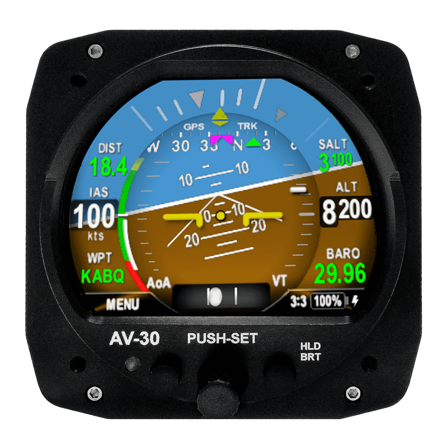
Pilot’s Guide to configure the display to show GPS navigational data in at least one textual display field. The image below shows a typical configuration that the pilot may setup. Figure 53 – GPS Data Elements UAV-1004234-001, AV-30-E Installation Manual Rev H... -
Page 120: Vibration Check
3. Rotate to “VIBE MONITOR” and press the center button. Figure 54 – Vibe Monitor Selection 4. The Vibration Monitor will display current and peak values for the Accelerometer and Gyroscope. UAV-1004234-001, AV-30-E Installation Manual Rev H... - Page 121 • Replace worn engine mounts and address causes of high engine vibration. • Ensure the AV-30-E is not mounted in a location subject to high vibration. This can often be detected by placing your hand on various locations in the panel, and can be caused by poorly supported panel regions, adjacent equipment, or proximity to engine structure.
-
Page 122: Air Data - Pitot-Static Zero
Air Data – Pitot-Static Zero 13.2.8 As the AV-30-E ages or is exposed to unusual conditions, the pressure sensors may age and require field adjustment to maintain accuracy. If the Indicated Airspeed (IAS) appears to be inaccurate, the Pitot and Static pressure sensors may have aged unevenly and yielding inaccurate readings. -
Page 123: Air Data - Altitude Trim
This function requires a calibrated air data test set connected to the AV-30-E to simulate multiple altitudes. To execute this function, go to the AI mode page on the AV-30-E and set the barometric pressure to 29.92. Now go to the installation menu and select ALT TRIM LO. -
Page 124: Air Data - Ias Trim
This function requires a calibrated air data test set connected to the AV-30-E to simulate multiple airspeeds. To execute this function, select the AI Mode on the AV-30-E. Go to the installation menu and select IAS TRIM LO. Set the air data test set to 45 knots or the stall speed or your aircraft, whichever is greater. -
Page 125: Av-Apa Checkout
If the ‘NO AP’ flag is present on startup, it is an indication that the AV-APA and AV-30-E are not communicating. Check wiring to resolve. The ‘NO AP’ flag can also indicate that the pilot has selected a mode and the required data isn’t available. -
Page 126: Emc Checkout
3. After confirming all existing avionics are functioning properly, power off all existing equipment. 4. Power on the AV-30-E and perform the following tests as they apply to the existing aircraft equipment. 5. Observe load shedding procedures as appropriate for the aircraft... - Page 127 VHF NAV RADIOS Verify VHF NAV operates without interference from the AV-30-E. 1. Power on the VHF NAV radio. 2. Monitor a local, remote, and unused frequency. 3. Verify there are no misleading navigation indications during the monitoring of each frequency.
-
Page 128: Troubleshooting
Set trim adjustment in Installation menu. See Installation Manual for instructions.. Set trim adjustment in Installation menu. See Airspeed or Altitude shows small but instructions… Section 13.2.8 Installation Manual for constant error. and section 13.2.9 UAV-1004234-001, AV-30-E Installation Manual Rev H... - Page 129 This indicates that the AV-30-E is either not communicating with the AV-APA (see above), or that “NO AP” flag is displayed when the AV-30-E does not have the required information to selecting an autopilot mode or while perform the mode selected. If using an autopilot mode...
-
Page 130: Serial Interface Specification
$GPRMB, Field 2 “I” Packet Desired Track Computed “K” Packet Waypoint ID $GPRMB, Field 5 $GPRMB, Field Bearing to Waypoint “L” Packet $GPRMC, Field “Q” Packet Magnetic Variation $GPRTE, “w” Packet Flight Plan $GPWPL UAV-1004234-001, AV-30-E Installation Manual Rev H... -
Page 131: Field Update Capability
The unit software can be field updated. Updating requires either an in- line harness and Windows based PC, or the optional AV-Link accessory to be installed. Contact uAvionix support for additional information, or reference available Service Bulletins. Figure 56 - Field Update Interface Diagram... -
Page 132: Appendix A: Example Wiring Schematics
17 Appendix A: Example Wiring Schematics Below are a series of example wiring diagrams showing interconnection between a variety of uAvionix and third-party equipment. While these diagrams show common configurations, they do not enumerate all combinations or options. Extrapolation or interpolation between diagrams may be necessary. - Page 133 UAV-1004234-001, AV-30-E Installation Manual Rev H...
- Page 134 UAV-1004234-001, AV-30-E Installation Manual Rev H...
- Page 135 UAV-1004234-001, AV-30-E Installation Manual Rev H...
- Page 136 UAV-1004234-001, AV-30-E Installation Manual Rev H...
- Page 137 UAV-1004234-001, AV-30-E Installation Manual Rev H...
- Page 138 UAV-1004234-001, AV-30-E Installation Manual Rev H...
- Page 139 UAV-1004234-001, AV-30-E Installation Manual Rev H...
Need help?
Do you have a question about the AV-30-E and is the answer not in the manual?
Questions and answers