uAvionix AV-30-E Installation Manual
Hide thumbs
Also See for AV-30-E:
- Installation manual (139 pages) ,
- Pilot's manual (101 pages) ,
- Service bulletin (37 pages)
Table of Contents
Advertisement
Advertisement
Table of Contents

Related Manuals for uAvionix AV-30-E


Summary of Contents for uAvionix AV-30-E
- Page 1 AV-30-E Installation Manual UAV-1004234-001 Rev C...
- Page 2 retained.
-
Page 3: Revision History
Initial release 1/12/2021 Software update 1.1.0 Software update 2.1.1 Added Transponder control Added AV-Link installation 7/22/2021 Added definition of acronyms & terms section Added magnetometer aiding and calibration Added requirement of pitot and static UAV-1004234-001, AV-30-E, Installation Manual Rev C... -
Page 4: Warnings / Disclaimers
2 Warnings / Disclaimers All device operational procedures must be learned on the ground. uAvionix is not liable for damages arising from the use or misuse of this product. This equipment is classified by the United States Department of Commerce's Bureau of Industry and Security (BIS) as Export Control Classification Number (ECCN) 7A994. -
Page 5: Limited Warranty
AV-30-E on the aircraft. For the duration of the warranty period, uAvionix, at its sole option, will repair or replace any product which fails in normal use. Such repairs or replacement will be made at no charge to the customer for parts or labor, provided that the customer shall be responsible for any transportation cost. -
Page 6: Table Of Contents
9.3 Internal Battery Operation ............22 9.3.1 General ................22 9.4 Internal Magnetometer (Optional) ..........22 9.4.1 General ................22 10 Equipment Installation ..............23 10.1 Overview ................23 10.2 Supplied Components ............23 10.3 Non-Supplied Components ..........23 UAV-1004234-001, AV-30-E, Installation Manual Rev C... - Page 7 13 Installation Menu ................ 40 13.1 Mandatory Settings ............43 13.1.1 Unit Function ..............43 13.1.2 Function Lock ..............43 13.1.3 Trim ................43 13.1.4 V-Speeds ..............43 13.1.5 Display Units ..............43 13.1.6 Serial Inputs ..............44 UAV-1004234-001, AV-30-E, Installation Manual Rev C...
- Page 8 13.2.2 Gyro Calibration ............47 13.2.3 Mag Calibration Flight ............ 49 13.2.4 OAT Interface ..............50 13.2.5 GPS Navigator Interface ..........50 14 Troubleshooting ................. 52 15 Serial Interface Specification ............53 16 Field Update Capability .............. 54 UAV-1004234-001, AV-30-E, Installation Manual Rev C...
-
Page 9: Introduction
Maximum velocity in smooth air (never exceed). The red line at the top end of the ASI yellow arc. Minimum control airspeed with the critical engine inoperative Speed for best rate of climb OEI (single engine) UAV-1004234-001, AV-30-E, Installation Manual Rev C... -
Page 10: System Information
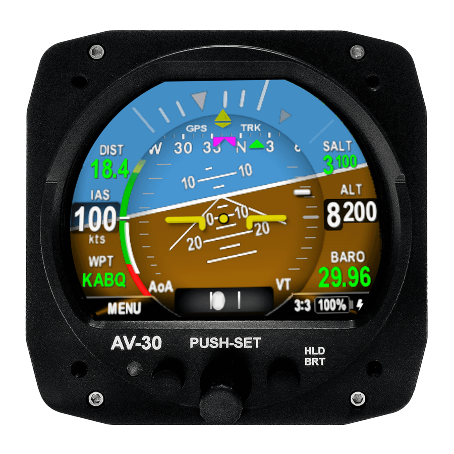
AV-30 multi-mode instrument. System Description The uAvionix AV-30 is a fully digital multi-mode instrument that mounts in the legacy 3-1/8” round instrument panel. It can be field configured as either an Attitude Indicator (AI), a Directional Gyro (DG) indicator or Multi-Function Display (MFD). - Page 11 2 hours in the event of aircraft power loss in flight and 30 minutes minimum under all temperature conditions. See UAV-1004233-001, AV-30-E, Pilot’s Guide for additional details. UAV-1004234-001, AV-30-E, Installation Manual Rev C...
-
Page 12: System Functions
- MFD traffic page with AV-Link - Transponder control Audio and Visual Alerting Functions: - AoA Alerting - G Limit Alerting - Excessive Roll Alerting Misc. Functions: - Internal Battery Operation - Auto / Manual Brightness UAV-1004234-001, AV-30-E, Installation Manual Rev C... - Page 13 Altitude 25,000 Feet (maximum) Optical Characteristics 3” Circular Diagonal Size Contrast Ratio (Typical) Brightness (Typical) 1000 cd/m Viewing Angle Left/Right 60° Viewing Angle Up 45° Viewing Angle Down 10° Backlight Lifetime (Typical) 50,000 Hours UAV-1004234-001, AV-30-E, Installation Manual Rev C...
-
Page 14: Design Standards
For aircraft capable of acrobatic flight, the AoA indication may become unreliable for operation in inverted flight and maneuvers exceeding ±8 G. For panels with more than 15 degrees of panel tilt, the AoA indication may not indicate correctly. UAV-1004234-001, AV-30-E, Installation Manual Rev C... -
Page 15: Applicable Performance Standards
Heading Reference Systems (AHRS) ASTM F3011-13 Standard Specification for Performance of Angle of Attack System RTCA DO-347 Certification Test Guidance for Small and Medium Size Medium Sized Rechargeable Lithium Batteries and Battery Systems UAV-1004234-001, AV-30-E, Installation Manual Rev C... -
Page 16: Installation Locations & Operating Modes
• Unit unlocked; can be toggled between AI, DG, and MFD mode by the pilot. If the functionality is not locked, pressing and holding the rotary knob will toggle between AI, DG, and MFD modes. UAV-1004234-001, AV-30-E, Installation Manual Rev C... -
Page 17: Functionality And Required Interfaces
Do not plug the pitot and static lines. Figure 3 – AV-30 Aircraft Systems Interfaces – AI Mode Figure 4 - AV-30 Aircraft Systems Interfaces – DG Mode UAV-1004234-001, AV-30-E, Installation Manual Rev C... -
Page 18: Feature Matrix
Auto / Manual Brightness None ✓ ✓ Transponder Control tailBeaconX serial & Pitot/static ✓ ✓ Traffic display AV-Link / GDL-90 / pitot / static ✓ ✓ Internal Magnetometer aid Optional hardware / Pitot / static UAV-1004234-001, AV-30-E, Installation Manual Rev C... -
Page 19: Power Input (Required)
This port connection is compatible with the Davtron P/N C307PS (not supplied). This is a differential two-wire current source based on the Analog Devices AD590KH component and supplies a current that corresponds to the ambient temperature. UAV-1004234-001, AV-30-E, Installation Manual Rev C... -
Page 20: Audio Output (Optional)
The GPS interface is an optional RS-232 serial input that is compatible with the industry standard “Aviation” output provided by most panel mounted GPS units, and NMEA serial interfaces provided by most hand-held GPS units. UAV-1004234-001, AV-30-E, Installation Manual Rev C... -
Page 21: Transponder Control (Optional)
The supported protocols are contained in Section 15- Serial Interface Specification. 9.2.6 Transponder Control (Optional) The AV-30 has the option of being the control interface for select uAvionix transponders (including the BeaconX family). This provides pressure altitude, mode, squawk code and IDENT information to the transponder, and displays status and annunciations from the transponder. -
Page 22: Internal Battery Operation
The internal magnetometer, when available, is detected in software version 2.1.1 or later. Application of magnetometer data requires calibration before use. If magnetometer is desired and is not detected, please contact uAvionix technical support to discuss upgrade options. See Section 13.2 on how to calibrate the AV-30 magnetometer. -
Page 23: Equipment Installation
Pitot Static T’s Quantity as required Circuit Breakers (2A) One required for each instrument OAT Probe Davtron P/N C307PS Power and Interconnect See AC 43.13-1B Chapter 11, Section 7 for Wire acceptable wire types UAV-1004234-001, AV-30-E, Installation Manual Rev C... -
Page 24: Mechanical Drawing
10.4 Mechanical Drawing Figure 5 – Mechanical Drawing UAV-1004234-001, AV-30-E, Installation Manual Rev C... -
Page 25: Mounting Screw Length Restriction
Correct screw length may be determined by inserting the supplied screw in the instrument panel (without the AV-30 Installed) and ensuring that either three or four full threads are exposed on the opposite side of the panel. Select alternate lengths as needed. UAV-1004234-001, AV-30-E, Installation Manual Rev C... -
Page 26: Wiring Diagrams
The primary difference is that the DG does not support audio alerting. See AC 43.13-1B Chapter 11 § 7 for acceptable wire types for both power and interconnect purposes. Figure 7 - Wiring Diagram – Attitude Indicator Position Installation UAV-1004234-001, AV-30-E, Installation Manual Rev C... -
Page 27: Bonding Requirements
The following figure shows the grounding requirements for the electrical connections. The two D-Sub screws are to be utilized for shield and ground strap connections. The supplied ring terminal connectors are sized for these screws. UAV-1004234-001, AV-30-E, Installation Manual Rev C... - Page 28 The bond between the unit (measured at the D-sub screws) to the aircraft frame must be 2.5 milli-Ohms or less. D-SUB BACK-SHELL GROUND STRAP < 8” AIRCRAFT GROUND CABLE SHIELD DRAIN < 2.5” Figure 10 –Cable Shields and Ground Strap UAV-1004234-001, AV-30-E, Installation Manual Rev C...
-
Page 29: Unit Pinout
Reserved - Do Not Connect OAT Return Input White / Blue Probe Wire Reserved – Do Not Connect MFG Serial Output POWER GPS SERIAL AUDIO Figure 11 – Unit Connections – DB-15, Male (Rear Unit View) UAV-1004234-001, AV-30-E, Installation Manual Rev C... -
Page 30: Optional Equipment Installation
AV-Link and AV-30, when paired with an ADS-B receiver, can display traffic information. This information is supplemental and for advisory use only. It cannot replace required equipment. 11.1.2 FCC ID Table 8 – FCC ID Model FCC ID AV-Link Contains 2AC7Z-ESPWROOM02U UAV-1004234-001, AV-30-E, Installation Manual Rev C... -
Page 31: Av-Link Specifications
Maximum pressure altitude 35,000 ft Input voltage range 9 to 30.3 VDC 0.2A idle 14V current 0.25A typical 0.5A maximum 0.1A idle 28V current 0.125A typical 0.25A maximum Figure 12 – AV-Link connector size UAV-1004234-001, AV-30-E, Installation Manual Rev C... -
Page 32: Av-Link Firmware
[4] screws that attach the AV-30 to the aircraft instrument panel. Pull unit down to a workable position. Note that it may also be necessary to disconnect the Pitot and Static lines to bring into reach. Ensure that the lines are properly labeled before disconnecting. UAV-1004234-001, AV-30-E, Installation Manual Rev C... -
Page 33: Backshell Connector Removal
Do not attempt to remove the two [2] captive Jack Screws from the AV-Link housing. Attach AV-Link to the back of the AV-30 by inserting the unit into the DB-15 connector on the back of the AV-30. Figure 11 - AV-Link attachment UAV-1004234-001, AV-30-E, Installation Manual Rev C... - Page 34 Using a 3/16” nut driver, tighten the two [2] Jack Screws to 5 in-lbs maximum. Do Not Overtighten! Reattach the original AV-30 Backshell Connector. Using a flat screwdriver, tighten the two [2] screws to 5 in-lbs maximum. Do Not Overtighten! Figure 15 – AV-Link attachment with backshell UAV-1004234-001, AV-30-E, Installation Manual Rev C...
-
Page 35: Reinstallation In Instrument Panel
1. Power AV-Link by attaching the AV-Link to AV-30 to provide power. 2. Once the AV-Link is powered, on your computer, connect to the AV-Link Wi-Fi hotspot, which will have an “AV_XXXX” SSID, where XXXX is a combination of alpha-numeric characters. UAV-1004234-001, AV-30-E, Installation Manual Rev C... -
Page 36: Wi-Fi Firmware Update Page
The AV-Link firmware update page permits firmware updating of AV-Link. Click on Choose File. Select the AV-Link firmware update file to load and then click the OK button. Click on Start Update to begin the firmware update process. UAV-1004234-001, AV-30-E, Installation Manual Rev C... -
Page 37: Transponder (Tailbeaconx)
ADS-B requirements for operating in controlled airspace worldwide, while minimizing installation costs. 11.2.1 Transponder Control See AV-30-E Pilot’s Guide UAV-1004233-001 for transponder control interface configuration. 11.2.2 Transponder Testing with tailBeaconX • Set AV-30 in STBY mode by following the above procedures. -
Page 38: Setup & Configuration
Operation in both AI and DG modes share common user interface controls as follows: TFT Color Display Left Push Button Right Push Button (Hold For Brightness Adjust) Photo Cell (Auto Screen Rotary Knob with Brightness) Momentary Push Figure 17 - Common User Interface Components UAV-1004234-001, AV-30-E, Installation Manual Rev C... -
Page 39: Available Menus
The edit fields menu allows the pilot to configure the display to show the various supplemental parameters in the desired locations. Details of this are covered in UAV-1004233-001, AV-30-E Pilot’s Guide and not addressed here. The Setup Menu allows the pilot to set various configurations and alerting limits as desired for the type of operations being performed. -
Page 40: Installation Menu
When in AI or DG mode, press and release the left MENU button three times until “INSTALL / ROT TO SEL” appears. The sequence of fields displayed is shown in Figure 14. UAV-1004234-001, AV-30-E, Installation Manual Rev C... - Page 41 Figure 15 - Exiting Edit Mode Pressing DONE or a lack of user input for 30 seconds will exit the installation menu and return to the primary screen. Figure 16 - Setup Done / Exit Option UAV-1004234-001, AV-30-E, Installation Manual Rev C...
- Page 42 Software part number For reference SW VERSION Software version For reference SW CHECKSUM Software checksum For reference SW CERT Software certification For reference * Initial factory value Initial and only option for units without magnetometer UAV-1004234-001, AV-30-E, Installation Manual Rev C...
-
Page 43: Mandatory Settings
• Set the IAS units to match that of the existing airspeed indicator. • Set the Baro units to match that of the existing altimeter. • Set OAT units to owner / pilot preference. UAV-1004234-001, AV-30-E, Installation Manual Rev C... -
Page 44: Serial Inputs
• SERIAL 3 If using the AV-Link, set SERIAL 3 to AVLINK to enable MFD page. Set to corresponding input type Value Serial 3 Source NONE None available AVLINK AV-Link is installed, MFD enabled UAV-1004234-001, AV-30-E, Installation Manual Rev C... -
Page 45: Aid Mode
Figure 17 - AID Mode Selection Push the center knob and rotate to select your choice of Magnetometer aiding and then push the center button to confirm your choice. 13.1.8 Demo Mode Set Demo Mode to DISABLED. UAV-1004234-001, AV-30-E, Installation Manual Rev C... -
Page 46: System Checkout
If power is removed from the unit while it is still aligning the unit will go to battery mode until it has completed the alignment process. Figure 18 - Aligning Annunciator If the indicator is not extinguished within 3 minutes, reference the troubleshooting section of this document for additional information. UAV-1004234-001, AV-30-E, Installation Manual Rev C... -
Page 47: Gyro Calibration
Do not leave the aircraft during the countdown. 4. Enter the “Install Menu” again. Rotate to Gyro Cal and push the center button to choose calibration. Confirm by pressing the right button. UAV-1004234-001, AV-30-E, Installation Manual Rev C... - Page 48 6. AV-30 will indicate “Calibration successfully completed Press DONE”. Push the left button under “DONE” and the calibration will be complete. If an error is shown, repeat the calibration process. If any post-accomplishment check fails, please contact uAvionix support. UAV-1004234-001, AV-30-E, Installation Manual Rev C...
-
Page 49: Mag Calibration Flight
MAG CAL will be disabled. Figure 23 - Mag Calibration Selection 3. Fly for 10 minutes. Four, 360-degree standard rate turns will need to be completed. Each turn will represent 25% of the total. UAV-1004234-001, AV-30-E, Installation Manual Rev C... -
Page 50: Oat Interface
If a GPS Navigator is connected, utilize the display customization guidance provided in the Pilot’s Guide to configure the display to show GPS navigational data in at least one textual display field. The image below shows a typical configuration that the pilot may setup. UAV-1004234-001, AV-30-E, Installation Manual Rev C... - Page 51 Figure 25 - GPS Data Elements On the GPS navigator, set a destination waypoint and initiate a direct-to sequence. Note that not all navigators will output serial data until a waypoint has been selected and navigation initiated. UAV-1004234-001, AV-30-E, Installation Manual Rev C...
-
Page 52: Troubleshooting
Ensure unswitched input is available on the audio panel. Verify volume setting is sufficiently high in the Setup menu. Ensure alerting limits are configured as desired in the Setup Nuisance alerts are generated. menu. UAV-1004234-001, AV-30-E, Installation Manual Rev C... -
Page 53: Serial Interface Specification
$GPRMB, Field 5 “L” Packet Bearing to Waypoint $GPRMB, Field 11 “Q” Packet Magnetic Variation $GPRMC, Field 10 “T” Packet, Flag 4 AT Master Flag $GPGGA, Field 6 “S” Packet, Flag 5 Garmin Master Flag UAV-1004234-001, AV-30-E, Installation Manual Rev C... -
Page 54: Field Update Capability
The unit software can be field updated. Updating requires either an in-line harness and Windows based PC, or the optional AV-Link accessory to be installed. Contact uAvionix support for additional information, or reference available Service Bulletins. Figure 26 - Field Update Interface Diagram...
Need help?
Do you have a question about the AV-30-E and is the answer not in the manual?
Questions and answers