uAvionix AV-30-E Installation Manual
Hide thumbs
Also See for AV-30-E:
- Installation manual (139 pages) ,
- Pilot's manual (101 pages) ,
- Service bulletin (37 pages)

Subscribe to Our Youtube Channel
Related Manuals for uAvionix AV-30-E


Summary of Contents for uAvionix AV-30-E
- Page 1 AV-30-E Installation Manual UAV-1004234-001, AV-30-E, Installation Manual Revision A...
- Page 2 retained.
-
Page 3: Revision History
1 Revision History Comments Revision Date 6/2/2020 Initial release UAV-1004234-001, AV-30-E, Installation Manual Revision A... -
Page 4: Warnings / Disclaimers
2 Warnings / Disclaimers All device operational procedures must be learned on the ground. uAvionix is not liable for damages arising from the use or misuse of this product. This equipment is classified by the United States Department of Commerce's Bureau of Industry and Security (BIS) as Export Control Classification Number (ECCN) 7A994. -
Page 5: Table Of Contents
3 Table of Contents 1 Revision History ................. 3 2 Warnings / Disclaimers ..............4 3 Table of Contents ................5 4 AV-30-E System Information ............. 7 4.1 System Description ..............7 4.2 System Functions ................ 9 4.3 System Specifications..............10 5 Design Standards ................ - Page 6 9.6.1 Alignment ................31 9.6.2 OAT Interface ............... 32 9.6.3 GPS Navigator Interface ............32 9.6.4 tailBeaconX control Interface ..........33 10 Troubleshooting ................34 11 Serial Interface Specification ............35 12 Field Update Capability ..............36 UAV-1004234-001, AV-30-E, Installation Manual Revision A...
-
Page 7: Av-30-E System Information
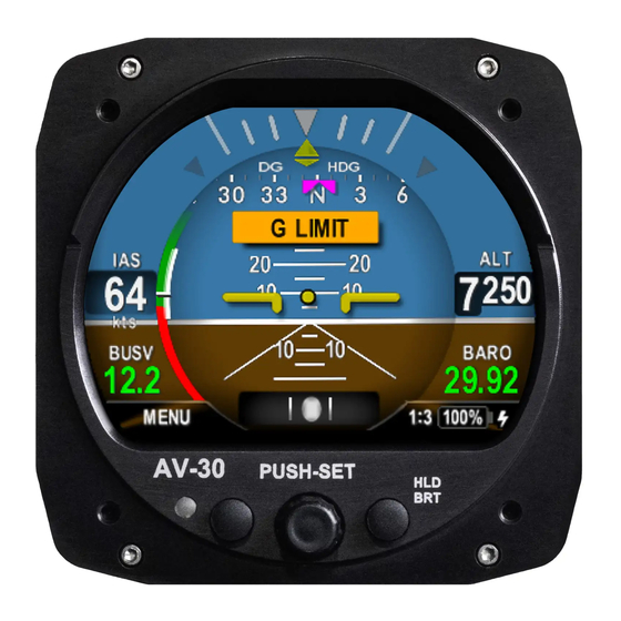
4 AV-30-E System Information System Description The uAvionix AV-30-E is a fully digital multi-mode instrument that mounts in the legacy 3 1/8” round instrument panel. It can be field configured as either an Attitude Indicator (AI) or a Directional Gyro (DG) indicator. - Page 8 An internal, rechargeable LiPo battery allows for operation for a nominal 2 hours in the event of aircraft power loss and 30 minutes minimum under all temperature conditions. UAV-1004234-001, AV-30-E, Installation Manual Revision A...
-
Page 9: System Functions
- GPS Navigator Route Line - Heading Bug Audio and Visual Alerting Functions: - AoA Alerting - G Limit Alerting - Excessive Roll Alerting Misc. Functions: - Internal Battery Operation - Auto / Manual Brightness UAV-1004234-001, AV-30-E, Installation Manual Revision A... -
Page 10: System Specifications
Optical Characteristics Diagonal Size 3” Circular Contrast Ratio (Typical) Brightness (Typical) 1000 cd/m Viewing Angle Left/Right 60° Viewing Angle Up 45° Viewing Angle Down 10° Backlight Lifetime (Typical) 50,000 Hrs Table 1 - System Specifications UAV-1004234-001, AV-30-E, Installation Manual Revision A... -
Page 11: Design Standards
Title 14 of the Code of Federal Regulation (CFR) and other related accepted procedures. The design basis for the AV-30-E is 14 CFR Part 23, Amendment 23-61. Installation is approved as a Level A system and is robust to High Intensity Radiated Field (HIRF) and lightning levels applicable for both metallic and non-metallic aircraft. -
Page 12: Applicable Performance Standards
Applicable Performance Standards The AV-30-E was designed to, and satisfied the applicable performance requirements defined in the following design standards: MOPS Title Category SAE AS8019 Airspeed Instruments Type B SAE AS392C Altimeter, Pressure Actuated, Sensitive Type I Type SAE AS8005A... -
Page 13: Installation Locations & Operating Modes
Operating Mode Configuration The AV-30-E operating mode is configured during installation and can be set as follows: • Unit locked as a dedicated Attitude Indicator (AI Mode) • Unit locked as a dedicated Direction Indicator (DG Mode) •... -
Page 14: Functionality And Required Interfaces
Static System Aircraft Power Optional Audio Out Analog Optional OAT Probe Analog Optional GPS Navigator Digital Figure 3 – AV-30-E Aircraft Systems Interfaces – AI Mode AV-30-C AIRCRAFT SYSTEMS Optional Pitot System Optional Static System Aircraft Power Optional Audio Out Analog... -
Page 15: Feature Matrix
Excessive Roll Alerting None Misc. Internal Battery Operation Pitot / Static Auto / Manual Brightness None tailBeaconX Control tailBeaconX serial Table 3 – Feature Matrix UAV-1004234-001, AV-30-E, Installation Manual Revision A... -
Page 16: Power Input (Required)
This architecture allows the unit to continue operation if external power fluctuates or is completely lost. Each AV-30-E must have a dedicated, properly labeled, pilot resettable circuit breaker as part of the installation. Power for the unit may be supplied from either the avionics bus or the main battery master relay. -
Page 17: Audio Output (Optional)
VFR operations only. The AV-30-E does no computations or operations on the data obtained from the GPS navigator, and simply displays the received data in a textual or graphical format as configured by the pilot. -
Page 18: Tailbeaconx Control (Optional)
The supported protocols are contained in Section 14- Serial Interface Specification. 7.2.6 tailBeaconX Control (optional) The AV-30-E has the option of being the transponder control interface for an installed tailBeaconX. This requires an RS-232 serial connection from the tailBeaconX to the AV-30-E. tailBeaconX can also act as your GPS source using the existing serial connection. -
Page 19: Equipment Installation
Non-Supplied Components Component Description Pitot / Static Tubing Length as required Pitot Static T’s Quantity as required Circuit Breakers (2A) One required for each instrument OAT Probe Davtron P/N C307PS Table 5 – Non-Supplied Components UAV-1004234-001, AV-30-E, Installation Manual Revision A... -
Page 20: Mechanical Drawing
Mechanical Drawing Figure 5 – Mechanical Drawing UAV-1004234-001, AV-30-E, Installation Manual Revision A... -
Page 21: Mounting Screw Length Restriction
Mounting Screw Length Restriction The AV-30-E is fastened to the instrument panel with four 6-32 screws. The unit mounts from the rear of the instrument panel, with the screws being inserted from the front of the panel. The four 6-32 Mounting screws must observe depth limits given the internal component design. -
Page 22: Wiring Diagrams
Wiring Diagrams The AV-30-E performs different functions when installed as an AI or DG, and therefore wiring varies based on installation. The following diagrams show connections for each configuration. The primary differences are that the DG does not require pitot or static connections (if the associated feature set is not desired), and audio alerting is not supported. - Page 23 MAY BE PARALLELED WITH SECOND AV-30-C AUDIO ALERTS NOT SUPPORTED WHEN INSTALLED AS DG – DO NOT CONNECT Figure 8 - Wiring Diagram – DG Position Installation Figure 9 - Wiring Diagram - tailBeaconX Installation UAV-1004234-001, AV-30-E, Installation Manual Revision A...
-
Page 24: Bonding Requirements
The bond between the unit (measured at the D-sub screws) to the aircraft frame must be 2.5 milli-Ohms or less D-SUB BACK-SHELL GROUND STRAP < 8” AIRCRAFT GROUND CABLE SHIELD DRAIN < 2.5” Figure 11 –Cable Shields and Ground Strap UAV-1004234-001, AV-30-E, Installation Manual Revision A... -
Page 25: Unit Pinout
OAT Return Input White / Blue Probe Wire Mfg Serial Output Reserved - DNC Table 6 – Connector Pinout POWER GPS SERIAL AUDIO Figure 12 – Unit Connections – DB-15, Male (Rear Unit View UAV-1004234-001, AV-30-E, Installation Manual Revision A... -
Page 26: Setup & Configuration
Operation in both AI and DG modes share common user interface controls as follows: TFT Color Display Left Push Button Right Push Button (Hold For Brightness Adjust) Photo Cell (Auto Screen Rotary Knob with Brightness) Momentary Push Figure 14 - Common User Interface Components UAV-1004234-001, AV-30-E, Installation Manual Revision A... -
Page 27: Available Menus
The Install Menu is for settings that are not normally required to be adjusted during flight. The installer must review and set these according to the installation configuration. UAV-1004234-001, AV-30-E, Installation Manual Revision A... -
Page 28: Install Menu Activation
Rotating the knob left and right will access the various parameters that may be configured. Pressing the knob when the desired field is shown will allow the associated setting to be adjusted. After adjustment, UAV-1004234-001, AV-30-E, Installation Manual Revision A... -
Page 29: Install Menu Settings
BEACON X Serial 2 Aux Serial Input Set to NONE Demo Mode Demo Mode Set to DISABLED Software Version Software Version For Reference Software Checksum Software Checksum For Reference Table 7 – Install Menu Options UAV-1004234-001, AV-30-E, Installation Manual Revision A... -
Page 30: Mandatory Settings
9.5.5 Display Units Set the IAS units to match that of the existing airspeed indicator. Set the Baro units to match that of the existing altimeter. Set OAT units to owner / pilot preference. UAV-1004234-001, AV-30-E, Installation Manual Revision A... -
Page 31: Serial Inputs
NONE. If connected to an Autopilot system using the APA Mini adapter, Set Serial 2 to APA Mini, if using the AV-30-E as a control head for a tailBeaconX Set Serial 2 to BeaconX, otherwise select NONE. -
Page 32: Oat Interface
Figure 20 – OAT Indication On the GPS navigator, set a destination waypoint and initiate a direct-to sequence. Note that not all navigators will output serial data until a waypoint has been selected and navigation initiated. UAV-1004234-001, AV-30-E, Installation Manual Revision A... -
Page 33: Tailbeaconx Control Interface
• Press in the center knob • Press in the center knob to select a squawk digit • Press the right button to quick squawk 1200 • Press the left button (DONE) to finish UAV-1004234-001, AV-30-E, Installation Manual Revision A... -
Page 34: Troubleshooting
Verify volume setting is sufficiently high in the pilots Setup Menus. Nuisance alerts are being generated Ensure alerting limits are configured as desired in the Setup Menus. Disable any un-desired alerting features in the Setup Menus. Table 8 – Trouble Shooting UAV-1004234-001, AV-30-E, Installation Manual Revision A... -
Page 35: Serial Interface Specification
“L” Packet $GPRMB, Field 11 Magnetic Variation “Q” Packet $GPRMC, Field 10 AT Master Flag “T” Packet, Flag 4 $GPGGA, Field 6 Garmin Master Flag “S” Packet, Flag 5 Table 9 - GPS Serial Specification UAV-1004234-001, AV-30-E, Installation Manual Revision A... -
Page 36: Field Update Capability
FEMALE USB TO RS- FEMALE 232 SERIAL CONVERTER NOTES: ADAPTER HARNESS ALLOWS UNIT TO BE POWERED BY AIRCRAFT BUS AV-30 DOES NOT NEED TO BE REMOVED FROM PANEL Figure 22 - Field Update Harness UAV-1004234-001, AV-30-E, Installation Manual Revision A...
Need help?
Do you have a question about the AV-30-E and is the answer not in the manual?
Questions and answers