
Related Manuals for uAvionix AV-30-S


Summary of Contents for uAvionix AV-30-S
- Page 1 AV-30-C Installation Manual UAV-1003947-001, AV-30-C, Installation Manual Revision C...
- Page 2 retained.
-
Page 3: Revision History
Revision History Revision Date Comments 4/24/2020 Initial release Added installation log-book entry requirement. Added method to determine proper screw length. Highlighted primary functions. Added 7/13/2020 items included in the ICA. Added startup time and AoA reference per MOPS requirement. Added reference to CFR 23.1321. Added reference to AoA operation in inverted flight and operation in excess of G limits. -
Page 4: Warnings / Disclaimers
Warnings / Disclaimers All device operational procedures must be learned on the ground. uAvionix is not liable for damages arising from the use or misuse of this product. This equipment is classified by the United States Department of Commerce's Bureau of Industry and Security (BIS) as Export Control Classification Number (ECCN) 7A994. -
Page 5: Table Of Contents
Table of Contents 1 Revision History ................3 2 Warnings / Disclaimers ..............4 3 Table of Contents ................5 4 AV-30-C System Information ............7 4.1 System Description ..............7 4.2 System Functions ..............9 4.3 System Specifications .............. 10 5 Certification ................... - Page 6 9.8 Bonding Requirements ............27 9.9 Unit Pinout ................28 10 Setup & Configuration ..............29 10.1 Startup and Common Controls ........... 29 10.2 Available Menus..............30 10.3 Install Menu Activation ............31 10.4 Install Menu Settings ............32 10.5 Mandatory Settings ............
-
Page 7: Av-30-C System Information
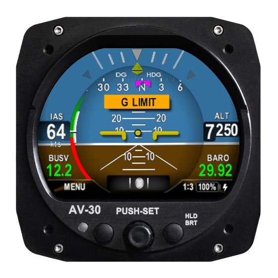
AV-30-C System Information System Description The uAvionix AV-30-C is a fully digital multi-mode instrument that mounts in the legacy 3 1/8” round instrument panel. It can be field configured as either an Attitude Indicator (AI) or a Directional Gyro (DG) indicator. It is fully self-contained with dual-precision inertial and pressure sensors and allows for a wide variety of pilot customization. - Page 8 instrumentation and preserve the look-and-feel of older aircraft applications. A wide variety of supplemental functions, including audio alerting, derived angle of attack presentation, g-load display, and more are provided. An internal, rechargeable LiPo battery allows for operation for a nominal 2 hours in the event of aircraft power loss and 30 minutes minimum under all temperature conditions.
-
Page 9: System Functions
System Functions Primary Functions: - Primary Attitude (AI Mode) - Primary Slip (AI Mode) - Primary Direction of Flight Indication (DG Mode) Supplemental Functions: - Indicated Airspeed - Altitude - V-Speeds - Angle Of Attack - Vertical Trend - Vertical Speed - Set Altitude - Heading - Bus Voltage... -
Page 10: System Specifications
System Specifications Electrical Attributes Input Voltage Nominal +10 to +32 VDC Input Voltage Max +60 VDC Input Power Nominal 6 Watts (0.5 Amps @ 12VDC) Input Power Max 12 Watts (1.0 Amps @ 12VDC) Required Circuit Breaker 2 Amp Operation on Battery 2 Hrs Typ @ 20°C / 30 Min Minimum @ -20C Physical Attributes Mounting Configuration... -
Page 11: Certification
Certification This installation manual provides mechanical and electrical information necessary to install the AV-30-C. The content of this manual assumes use by competent and qualified personnel using standard maintenance procedures in accordance with Title 14 of the Code of Federal Regulation (CFR) and other related accepted procedures. -
Page 12: Mechanical Instrument Replacement
Mechanical Instrument Replacement Approval is granted to replace legacy mechanical instrumentation as follows: Installation of the AV-30-C (Dedicated AI mode) as the primary source for attitude and slip. Installation replaces the existing stand-alone vacuum or electrically powered attitude indicator. ... -
Page 13: Applicable Performance Standards
Applicable Performance Standards The AV-30-C was designed to, and satisfied the applicable performance requirements defined in the following design standards: MOPS Title Category SAE AS8019 Airspeed Instruments Type B SAE AS392C Altimeter, Pressure Actuated, Sensitive Type I Type SAE AS8005A Standard Temperature Instruments Class IIIc SAE AS8034... -
Page 14: Installation Limitations
Installation Limitations The following section provides the FAA approved installation limitations. Installation Approval Limitations This article meets the minimum performance and quality control standards required by an Approved Model List - Supplemental Type Certificate (AML-STC) and when installed on aircraft approved on the AML can be approved for return to service after installation. -
Page 15: Installation Locations & Operating Modes
Installation Locations & Operating Modes Installation Locations The following figure shows a typical “six-pack” and one possible arrangement of instrument locations: AI/DG Figure 2 – Mechanical Gauge Replacement Note that the physical arrangement in many aircraft varies from the traditional “T” configuration shown above. The AI/DG locations are examples of installation locations as a non-required instrument. -
Page 16: Operating Mode Configuration
Operating Mode Configuration The AV-30-C operating mode is configured during installation and can be set as follows: Unit locked as a dedicated Attitude Indicator (AI Mode) Unit locked as a dedicated Direction Indicator (DG Mode) Unit can be toggled between AI and DG mode by the pilot Installations where dedicated functionality is required must have the associated setting configured in the setup procedures. -
Page 17: Functionality And Required Interfaces
Functionality and Required Interfaces Aircraft Systems Connections All aircraft systems connections are provided on the single 15-Pin D- sub connector and two quick-connect pneumatic fittings. Various interfaces are optional as indicated in the following diagrams. AV-30-C AIRCRAFT SYSTEMS Pitot System Static System Aircraft Power Optional Audio Out... -
Page 18: Feature Matrix
Feature Matrix The following matrix shows primary and supplemental data and any required external interface. Feature AI Mode DG Mode Required Interface Primary Attitude and Slip Primary Attitude None Primary Slip None Reversionary Attitude / Slip ... -
Page 19: Power Input (Required)
8.2.1 Power Input (Required) Power input is required and connects to the aircraft’s power bus. Input range is compatible with both 12V and 24V aircraft. Internally, this power is diode OR’ed with the internal battery via a processor- controlled switch. This architecture allows the unit to continue operation if external power fluctuates or is completely lost. -
Page 20: Audio Output (Optional)
The OAT probe is automatically detected by the system, and when detected, allows temperature related parameters to be selected for display by the pilot. If the OAT probe is not detected, display of these parameters will automatically be inhibited. 8.2.4 Audio Output (Optional) The optional audio panel connection is a low-voltage analog output that is designed to connect directly to an audio panel (typically a non-switched input). -
Page 21: Internal Battery Operation
This serial interface may be connected in parallel between multiple AV-30 units and is supported in both the AI and DG modes. The supported protocols are contained in Section 14- Serial Interface Specification. Internal Battery Operation 8.3.1 General The internal battery consists of a rechargeable LiPo battery system with automatic recharge, self-test and power switching capability. -
Page 22: Equipment Installation
Equipment Installation Overview Installation consists of the following steps: Remove / relocate any legacy instrumentation Add or locate an appropriate power source / breaker Wire power and systems interfaces as needed Mount the unit to the instrument panel with supplied screws ... -
Page 23: Mechanical Drawing
Mechanical Drawing Figure 5 – Mechanical Drawing UAV-1003947-001, AV-30-C, Installation Manual Revision C... -
Page 24: Mounting Screw Length Restriction
Mounting Screw Length Restriction The AV-30-C is fastened to the instrument panel with four 6-32 screws. The unit mounts from the rear of the instrument panel, with the screws being inserted from the front of the panel. The four 6-32 Mounting screws must observe depth limits given the internal component design. -
Page 25: Wiring Diagrams
Wiring Diagrams The AV-30-C performs different functions when installed as an AI or DG, and therefore wiring varies based on installation. The following diagrams show connections for each configuration. The primary differences are that the DG does not require pitot or static connections (if the associated feature set is not desired), and audio alerting is not supported. - Page 26 ROTATING THE PLASTIC TUBE WHILE REMOVING WILL MINIMIZE RISK OF DAMAGING THE QUICK-CONNECT FITTING AV-30-C QUICK CONNECT: PUSH RELEASE RING IN TOWARD UNIT TO RELEASE AV-20 OPTIONAL AIRCRAFT STATIC SYSTEM ¼ “ OD NYLON / POLYETHYLENE TUBE (OR EQ) RELEASE OPTIONAL AIRCRAFT PITOT SYSTEM AIRCRAFT POWER...
-
Page 27: Bonding Requirements
Bonding Requirements The following figure shows the grounding requirements for the electrical connections. The two D-Sub screws are to be utilized for shield and ground strap connections. The supplied ring terminal connectors are sized for these screws. The ground braid strap is to be less than 8 inches in overall length and at least 3/16 width. -
Page 28: Unit Pinout
Unit Pinout Function Type Comment Power Power +12 to +28 VDC GPS Navigator Input GPS RS-232 Spare Serial Output Reserved - Do Not Connect Spare Serial Input Reserved - Do Not Connect Spare Serial Output Reserved - Do Not Connect Spare Serial Input Reserved - Do Not Connect... -
Page 29: Setup & Configuration
10 Setup & Configuration 10.1 Startup and Common Controls When powered on, the initial splash screen presents the company logo, unit model number, and the currently installed software version. Figure 12 – Splash Screen Operation in both AI and DG modes share common user interface controls as follows: TFT Color Display Left Push Button... -
Page 30: Available Menus
10.2 Available Menus Setup and configuration menus are divided into three categories as follows: - Edit Fields Menu (Pilot accessible) - Setup Menu (Pilot Accessible) - Install Menu (Non-Pilot Accessible) The Edit Fields Menu allows the pilot to configure the display to show the various supplemental parameters in the desired locations. -
Page 31: Install Menu Activation
10.3 Install Menu Activation To access the Install Menu, ensure the unit is turned off. Press and hold the main control knob in while power is applied. Push and Hold While Applying Power Figure 14 – Installation Menu Access Keep the knob pressed until the startup logo has cleared. The Install Menu will now be enabled for access. -
Page 32: Install Menu Settings
Rotating the knob left and right will access the various parameters that may be configured. Pressing the knob when the desired field is shown will allow the associated setting to be adjusted. After adjustment, pressing the knob again will disable the editing mode but the Install Menu will remain active. -
Page 33: Mandatory Settings
10.5 Mandatory Settings The following settings are mandatory for each installation: 10.5.1 Unit Function Set to AI if installation is replacing an existing Attitude Indicator. Set to DG if installation is replacing and existing Direction Indicator. Set to either when installation is as a non-required instrument. In this mode, this setting is the initial default operating mode if the function lock below is not set to locked. -
Page 34: Display Units
10.5.5 Display Units Set the IAS units to match that of the existing airspeed indicator. Set the Baro units to match that of the existing altimeter. Set OAT units to owner / pilot preference. 10.5.6 Serial Inputs Set GPS Nav Source to the corresponding GPS navigator input type. -
Page 35: Oat Interface
10.6.2 OAT Interface If an OAT probe is connected, utilize the display customization guidance provided in the Pilots Guide to configure the display to show OAT in at least one textual display field. Figure 18 – OAT Indication Note that OAT calibration is performed in the Setup procedures. This step only ensures that the OAT probe is detected properly. -
Page 36: Emc Checkout
10.6.4 EMC Checkout An EMC check should be performed after the AV-30-C installation is complete. The EMC check verifies that the newly installed equipment is not producing interference to other avionics and that the existing avionics are not producing interference to the AV-30-C. The testing assumes the AV-30-C operational check has been completed and that the installed avionics to be tested are all in working condition. - Page 37 Monitor a remote (distant) frequency and verify there are no unintended squelch breaks or other tones that would interfere with communications. Monitor an unused frequency and verify there are no unintended squelch breaks or other tones that would interfere with communications.
-
Page 38: Troubleshooting
11 Troubleshooting The following steps are to aid in identifying installation or unit performance related issues: Issue Possible Resolution Power Related Issues Unit does not power-on Check associated breakers. Ensure aircraft battery is greater than 10VDC. Check wiring and pinouts. Unit will not shut-off, even if power Ensure no pitot static blockage or line kinks are is removed... -
Page 39: Instructions For Continued Maintenance & Operation
12 Instructions for Continued Maintenance & Operation See UAV-1004045-001, AV-30-C, Instructions for Continued Airworthiness (ICA) for replacement, inspection requirements and procedures. The ICA addresses the following aspects of continued airworthiness: Visual Inspection Procedure Altimeter Test and Calibration Battery Test and Replacement Procedure 13 Aircraft Flight Manual Supplements See UAV-1004044-001, AV-30-C, Flight Manual Supplement for normal, emergency and limitations as required by CFR §23.1581. -
Page 40: Serial Interface Specification
14 Serial Interface Specification GPS serial input is compatible with the “Aviation” and NMEA serial protocols. Aviation protocol is 9600 Baud, No Parity, 8 Data Bits, 1 Stop bit. NMEA is either 4800 or 9600 Baud, No Parity, 8 Data Bits, 1 Stop Bit. -
Page 41: Field Update Capability
15 Field Update Capability The unit software is field updateable and requires an in-line harness and Windows based PC. Contact the factory for additional information. AV-30 AV-20 ADAPTER HARNESS EXISTING AIRCRAFT (~5 TO ~12 INCHES LONG) WIRING AIRCRAFT POWER 1-AMP BREAKER SER OUT SER IN 15 PIN DSUB...
Need help?
Do you have a question about the AV-30-S and is the answer not in the manual?
Questions and answers