uAvionix AV-30-E Pilot's Manual
Hide thumbs
Also See for AV-30-E:
- Installation manual (139 pages) ,
- Pilot's manual (101 pages) ,
- Service bulletin (37 pages)
Table of Contents
Advertisement
Quick Links
Advertisement
Table of Contents

Related Manuals for uAvionix AV-30-E


Summary of Contents for uAvionix AV-30-E
- Page 1 AV-30-E Pilot’s Guide UAV-1004233-001 Rev. H...
- Page 2 retained.
-
Page 3: Revision History
“zero out” action of the DG adjustment if using AV-Mag. Added table of checks and alerts for stored parameter integrity. Added three new autopilot heading modes and descriptions. Added GPS error messages table. Added AI UAV-1004233-001, AV-30-E Pilot’s Guide Rev. H Page... - Page 4 1:3, 2:3, 3:3 default screens. Updated Angle Of Attack Limit setting instructions to match the AV-30-C Pilot’s Guide. 2/27/2023 Updated CRC check splash messages. Update AV-Link for latest release (0.3.0) and new IP (192.168.5.1). UAV-1004233-001, AV-30-E Pilot’s Guide Rev. H Page...
-
Page 5: Warnings / Disclaimers
2 Warnings / Disclaimers All device operational procedures must be learned on the ground. uAvionix is not liable for damages arising from the use or misuse of this product. This equipment is classified by the United States Department of Commerce's Bureau of Industry and Security (BIS) as Export Control Classification Number (ECCN) 7A994. -
Page 6: Limited Warranty
3 Limited Warranty uAvionix products are warranted to be free from defects in material and workmanship for two years from the installation of AV-30-E on the aircraft. For the duration of the warranty period, uAvionix, at its sole option, will repair or replace any product which fails in normal use. -
Page 7: Table Of Contents
Revision History ................. 3 Warnings / Disclaimers ............... 5 Limited Warranty ................6 Table of Contents ................7 AV-30-E System Information ............11 System Description ..............11 System Functions ..............12 Unit Interfaces .................. 14 Aircraft Systems Interfaces ............14 Power Input (Required) ............. - Page 8 Target Relative Altitude ............45 7.8.6 Target Airspeed ..............46 7.8.7 Target Tracking Function ............. 46 7.8.8 Accessing Reversionary AI ..........47 7.8.9 Traffic Mode Configuration ........... 48 Reversionary AI ................. 51 7.10 Transponder Control ..............51 UAV-1004233-001, AV-30-E Pilot’s Guide Rev. H Page...
- Page 9 11.5 Setting AoA Lower Limit ............64 11.6 AoA Alert Types and Thresholds ..........65 11.7 Flap Setting Observations ............65 12 Setup Menu ..................67 12.1 Pilot-Accessible Setup Menu ............. 68 12.2 Non-Pilot Accessible Install Menu ..........69 UAV-1004233-001, AV-30-E Pilot’s Guide Rev. H Page...
- Page 10 14.1 Selecting Heading ..............77 14.2 Selecting Altitude ............... 77 14.3 Selecting Vertical Speed ............77 14.4 Selecting Autopilot Mode ............78 15 Stored Data Integrity Check ............. 79 16 Operating Limits & System Specifications ........80 UAV-1004233-001, AV-30-E Pilot’s Guide Rev. H Page...
-
Page 11: Av-30-E System Information
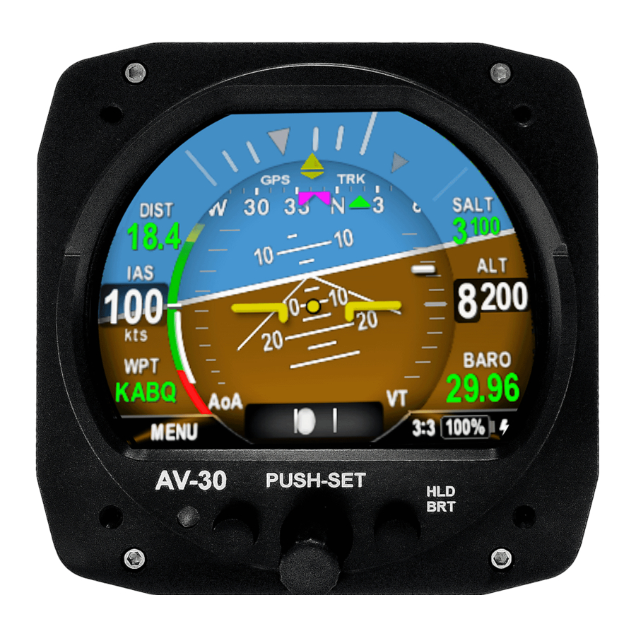
5 AV-30-E System Information 5.1 System Description The uAvionix AV-30-E is a fully digital multi-mode instrument that mounts in the legacy 3-1/8” round instrument panel. It can be field configured as either an Attitude Indicator (AI), a Directional Gyro (DG) indicator or Multi- Function Display (MFD). -
Page 12: System Functions
Primary Attitude (AI Mode) Primary Slip (AI Mode) Primary Direction of Flight indication (DG Mode) Supplemental Functions Indicated Airspeed Altitude V-Speeds Angle of Attack Vertical Trend Vertical Speed Set Altitude (SALT) Set Vertical Speed (SVS) UAV-1004233-001, AV-30-E Pilot’s Guide Rev. H Page... - Page 13 Transponder control (AI / DG / MFD Mode) Autopilot control Audio and Visual Alerting Functions AoA Alerting G Limit Alerting Excessive Roll Alerting Set Altitude Alerting Miscellaneous Functions Internal Battery Operation Auto/Manual Brightness UAV-1004233-001, AV-30-E Pilot’s Guide Rev. H Page...
-
Page 14: Unit Interfaces
The following describes each of the AV-30-E system interconnects for both the AI, DG and MFD installation configurations. Note that, as shown in Figure 2 – AV-30-E Aircraft Systems Interfaces – AI Mode, that some interfaces are optional and may not be available in each installation. -
Page 15: Power Input (Required)
This architecture allows the unit to continue operation if external power fluctuates or is completely lost. When external power is supplied to the AV-30-E, there is no mechanism to turn the unit off. When operating on battery, the unit may be forced off by pressing the left and right buttons simultaneously until the unit shuts off. -
Page 16: Pitot And Static Interfaces (Required)
This output does not provide IFR compliant lateral or vertical guidance, therefore all deviation related data presented is for VFR operations only. The AV-30-E does not alter the data obtained from the GPS navigator and simply displays the received data in a textual or graphical format as configured by the pilot. -
Page 17: Oat Probe (Optional)
Audio alerting is only supported when configured as an AI. 6.7 Transponder Control (Optional) The AV-30-E has the option of being the control interface for select uAvionix transponders (including the BeaconX family). This provides pressure altitude, mode, squawk code and IDENT information to the transponder, and displays status and annunciations from the transponder. -
Page 18: Magnetometer Aiding (Optional)
6.10 Autopilot (Optional) The AV-30-E has the option to act as an altitude and direction control input for the BendixKing AeroCruze 100/xCruze 100/TruTrak Vizion (385 and PMA) autopilot or the Trio ‘Pro Pilot’ autopilot. The autopilot and AV-30-E are connected to one another via half duplex RS-232 serial. - Page 19 There are four autopilot control modes. Each mode uses a different combination of desired direction and current direction to achieve different types of flight goals as show in Table 14-1- Autopilot Modes. For further details on Autopilot control see section 14 Autopilot. UAV-1004233-001, AV-30-E Pilot’s Guide Rev. H Page...
-
Page 20: User Interface
Operation in AI, DG and MFD modes share the following common user interface controls. TFT Color Display Left Push Button Right Push Button (Hold For Brightness Adjust) Photo Cell (Auto Screen Rotary Knob with Brightness) Momentary Push Figure 5 - Common User Interface Components UAV-1004233-001, AV-30-E Pilot’s Guide Rev. H Page... -
Page 21: Push-Set" Control
DG, and MFD modes when the Function Lock feature is disabled. If the Function Lock feature is enabled, then the pilot may not switch between modes. See AV-30-E Installation Manual UAV1004234-001 for configuring the Function Lock feature. 7.2 “PUSH-SET” Control Activate the PUSH-SET window for accessing context menus and settings by momentarily pushing and releasing the main rotary knob. -
Page 22: Direct-Turn
2:3 (second of three) is configured to show Angle of Attack and Vertical trend, while screen 3:3 (third of three) is configured to show GPS navigation waypoints and related data. UAV-1004233-001, AV-30-E Pilot’s Guide Rev. H Page... - Page 23 Figure 7 - Screen 1 of 3 showing Air Data and DG Heading Figure 8 – Screen 2 of 3 showing GPS Ground Track, AoA, and Vertical Trend UAV-1004233-001, AV-30-E Pilot’s Guide Rev. H Page...
-
Page 24: Ai Mode Customization
Pressing the lower left options MENU button will bring up the first menu, which is the user interface customization menu. In this mode, the cursor can be moved to each customizable area by rotating the rotary knob. UAV-1004233-001, AV-30-E Pilot’s Guide Rev. H Page... - Page 25 Figure 11 – UI Customization - Field Selection A second push of the lower left options MENU button will bring up the second menu. Menu options related to the current screen are displayed. UAV-1004233-001, AV-30-E Pilot’s Guide Rev. H Page...
-
Page 26: Edit Presented Data
7.5 AI Mode Display Components 7.5.1 Basic Components Figure 13 – Basic AI Mode User Interface shows the basic AI with all customizable data overlay fields turned off. The data shown cannot be disabled or customized: UAV-1004233-001, AV-30-E Pilot’s Guide Rev. H Page... -
Page 27: Customizable Data Overlay Fields
Figure 15 – Data Overlay Examples shows an example of the pilot customizable data overlays (both textual and graphical), located in the non-utilized areas of the display area. UAV-1004233-001, AV-30-E Pilot’s Guide Rev. H Page... -
Page 28: Attitude / Slip
Return to page 1 by momentarily pushing and releasing the page selection button. 7.5.3 Attitude / Slip The basic display of attitude and slip consists of a traditional attitude indicator display and slip-ball as follows: UAV-1004233-001, AV-30-E Pilot’s Guide Rev. H Page... -
Page 29: Airspeed Indicator
3 minutes, please contact uAvionix support. 7.5.4 Airspeed Indicator Indicated airspeed is configured for display on the left side of the screen. The configured units (KTS or MPH) are displayed below the speed value. UAV-1004233-001, AV-30-E Pilot’s Guide Rev. H Page... - Page 30 Figure 18 - AI Mode, V-Speed Limits On initial startup, the airspeed field will display dashes while sensor stabilization occurs. Airspeed display units and V-Speed limits are configured during installation and are not pilot accessible. UAV-1004233-001, AV-30-E Pilot’s Guide Rev. H Page...
-
Page 31: Flight Direction Indicator
Both modes support a magenta heading bug, and the GPS track mode supports an additional green bearing-to indicator. The heading bug may be used as a simple directional reference. In the case where the AV-30-E is connected to an autopilot, the heading bug is used as the direction input to the autopilot (See §6.10). -
Page 32: Aoa Indication
Derived Angle of Attack can be configured for display in the inner left area of the screen and consists of a series of colored stacked bars that indicates the current AoA relative to the configured minimum and maximum limits. UAV-1004233-001, AV-30-E Pilot’s Guide Rev. H Page... -
Page 33: Vertical Trend Indicator
Vertical trend can be configured for display in the inner right area of the screen and consists of a white tick mark on a background scale. The upper and lower limits of the scale correspond to ±1000 feet per minute. UAV-1004233-001, AV-30-E Pilot’s Guide Rev. H Page... - Page 34 SVS value is above or below the scale. Figure 25 - SVS Bug value greater than scale UAV-1004233-001, AV-30-E Pilot’s Guide Rev. H Page...
-
Page 35: G-Load Indicator
7.5.10 Text Fields The four corners of the display screen can be configured to show various textual parameters. In this example, distance to waypoint, waypoint identifier, Set Altitude, and barometric pressure are displayed. UAV-1004233-001, AV-30-E Pilot’s Guide Rev. H Page... -
Page 36: Accessing Reversionary Ai
DG mode has three customizable screens plus a reversionary AI screen for transponder control. 7.6.2 Non-Slaved Heading Mode Figure 28 – Basic DG Mode User Interface shows the non-slaved DG heading mode (DG HDG). Six textual fields are available for customization. UAV-1004233-001, AV-30-E Pilot’s Guide Rev. H Page... -
Page 37: Gps Hsi Mode
HSI format: Bearing To & Heading Bug Display Mode (GPS Track) Course To Course Deviation Nav Mode (VFR Only) Fixed Deviation Scale ( 1 nm Per Dot) Figure 29 – GPS HSI Mode UAV-1004233-001, AV-30-E Pilot’s Guide Rev. H Page... -
Page 38: Gps Arc Mode
1, 2, 5, 10, 20, 50 and 100 N Mi All GPS deviation data is limited to VFR operations only, as indicated by the Nav Mode indication (“VFR”). 7.6.5 Operational Aspects The following applies to operation in DG mode. UAV-1004233-001, AV-30-E Pilot’s Guide Rev. H Page... - Page 39 PUSH-SET menu, advancing to DG ADJ, then pushing and holding the center knob for 2 seconds. The heading will snap to the value computed by the AV-30-E and the user entered adjustment will be set to zero. Note that this only applies when the AV-Mag is installed.
-
Page 40: Accessing Reversionary Ai
AI and DG modes. The ‘Graphical’ presentation type indicates that the data is displayed in a graphical format (dial, tape, bug, etc.). The ‘Textual’ presentation type indicates that the data is displayed in text. UAV-1004233-001, AV-30-E Pilot’s Guide Rev. H Page... - Page 41 (4) Only available when Autopilot is installed and Vertical Trend Indicator is visible (5) Only available when OAT sensor is installed (6) Only available when a GPS navigator is installed (7) Some autopilot modes will hide the heading bug UAV-1004233-001, AV-30-E Pilot’s Guide Rev. H Page...
-
Page 42: Mfd Mode
7.8 MFD Mode When equipped, the AV-30-E can display real-time traffic data. To access the MFD mode page, ensure that SERIAL 3 is configured for ‘AVLINK’, and then push and hold the center button until the screen changes. If you are on the AI mode screen, you will change to the DG mode screen. -
Page 43: Firmware Update
7.8.2 Firmware Update After the AV-Link-E and AV-30-E have been installed, a firmware update may be required to enable the AV-Link-E features of the AV-30-E. See AV- 30-E Installation Manual UAV1004234-001 for instructions on installing firmware. A minimum software version of 2.0.0 is required to support MFD Mode. -
Page 44: Display Functions
As zoom is set to closer distances, extra target information will be placed next to the target icon. These include relative altitude to ownship and the speed vector extending from the front of the target. UAV-1004233-001, AV-30-E Pilot’s Guide Rev. H Page... -
Page 45: Target Relative Altitude
If the same altitude type is not available for both ownship and the target, then no relative altitude is displayed for that target. Note: AV-30-E must be connected to aircraft pitot and static pneumatic connections for correct relative altitudes to be displayed. -
Page 46: Target Airspeed
This is not in compliance with DO-317C §2.3.5.15.1 and therefore may result in a difference between the relative altitude display on the AV-30-E and the other product. Relative altitude is displayed in units of hundreds of feet. For example, a display of +335 indicates that the target is 33,500 feet above ownship. -
Page 47: Accessing Reversionary Ai
A reversionary style display of attitude and slip is available from the traffic page. Push and release the right button to engage this screen. Push and release the right button again to disengage. UAV-1004233-001, AV-30-E Pilot’s Guide Rev. H Page... -
Page 48: Traffic Mode Configuration
Every ADS-B In system occasionally displays a ghost, even for those aircraft equipped with ADS-B Out. Entering your ownship ICAO can remove that identified ghost from the traffic screen. UAV-1004233-001, AV-30-E Pilot’s Guide Rev. H Page... - Page 49 Ownship ICAO can be entered manually using the OWNSHIP ICAO menu entry. Once entered, the value is saved but can be changed at any time. If a uAvionix transponder is installed, and transponder control is enabled, ownship is automatically detected and entered for you on this screen.
- Page 50 None. Displays all traffic. Press and release, then rotate center knob to select Ownship Dependent on each number or letter associated with aircraft ICAO. ICAO. registration number. This will allow for ownship filtering. UAV-1004233-001, AV-30-E Pilot’s Guide Rev. H Page...
-
Page 51: Reversionary Ai
Transponder Control for details on transponder control. 7.10 Transponder Control When installed and configured, the AV-30-E can be used to control select uAvionix transponders (including the BeaconX family). The transponder controls are available on the Reversionary AI page in each mode. -
Page 52: Changing Squawk
• Rotate the center knob to change the highlighted squawk digit • Press and release the center knob to accept the changed squawk • Press and release the left button (DONE) to finish and save the setting UAV-1004233-001, AV-30-E Pilot’s Guide Rev. H Page... -
Page 53: Changing Flight Id
In operation, there are two ways to change the squawk code to the default VFR code: • Press and hold the left button until the VFR squawk code is shown in the SQWK field UAV-1004233-001, AV-30-E Pilot’s Guide Rev. H Page... -
Page 54: Brightness Menu
1 to 100. When in automatic brightness mode, the display brightness adjusts set automatically based on the bezel-mounted photocell. Pressing the DONE button will exit the menu and save the setting. UAV-1004233-001, AV-30-E Pilot’s Guide Rev. H Page... -
Page 55: User Interface And Font Style Options
The three UI styles are LEGACY, EFIS and VINTAGE. The two font selections are ARIAL and LCD. Figure 41 - UI Style Options These settings only effect the displayed colors and font style – all functional operations are identical regardless of style settings. UAV-1004233-001, AV-30-E Pilot’s Guide Rev. H Page... -
Page 56: Alerts And Alert Limits
Figure 42 shows an example how the visual alerts are displayed. Figure 42 – Example of Alert Annunciator on Screen The priority and warning / alert levels, from the lowest priority to the highest priority are found in Table 9-1. UAV-1004233-001, AV-30-E Pilot’s Guide Rev. H Page... -
Page 57: Altitude Alert
The Set Altitude alert is a visual alert only. It is signaled by the Set Altitude text display changing from white to green. Green indicates that the barometric corrected altitude is within ±100’ of the Set Altitude. UAV-1004233-001, AV-30-E Pilot’s Guide Rev. H Page... -
Page 58: Internal Battery Operation
“FAIL” in red, and no battery capability will be available. Figure 43- Battery Test Indicators If the battery status shows “FAIL”, departure into actual or planned IFR conditions must not be performed. UAV-1004233-001, AV-30-E Pilot’s Guide Rev. H Page... -
Page 59: Power Loss, Airspeed Above 40 Knots (In-Flight)
The battery charge state is shown in percentage from 0 to 100. An internal battery charger will re-charge the battery if bus voltage is above approximately 10 VDC. The battery charge icon (presented adjacent to UAV-1004233-001, AV-30-E Pilot’s Guide Rev. H Page... - Page 60 Figure 45 - Battery Charge Status. Figure 45 - Battery Charge Status It is normal for the battery charge icon to intermittently flash during the battery charge cycle. UAV-1004233-001, AV-30-E Pilot’s Guide Rev. H Page...
-
Page 61: Aoa Operation And Configuration
One of the main advantages of an AoA system is that it can provide an early indication of a stall, bringing enhanced awareness to the pilot. However, the AV-30-E system is supplemental in nature and does not replace the functionality provided by the aircraft’s existing stall warning system. -
Page 62: Configured Limits
• A lower limit is configured to coincide with the AoA at which the aircraft flies under normal cruise conditions. This is typically on the order of 3 to 4 degrees. This visually correlates to the lowest one or two green bars on the AoA display. UAV-1004233-001, AV-30-E Pilot’s Guide Rev. H Page... -
Page 63: Stable Flight Conditions
The objective is to set the upper AoA limit such that the first red bar illuminates at roughly the same time as the on-set of the aircraft’s stall warning system. To find the upper limit, the following procedure is recommended: UAV-1004233-001, AV-30-E Pilot’s Guide Rev. H Page... -
Page 64: Setting Aoa Lower Limit
• Select a safe altitude suitable for stalls, minimum 1,500 feet AGL. • Aircraft Configuration: o Airspeed V o Flaps 0 ° o Power as required o Stable flight conditions • Monitor the displayed AoA. UAV-1004233-001, AV-30-E Pilot’s Guide Rev. H Page... -
Page 65: Aoa Alert Types And Thresholds
The pilot should document the actual indications provided for the various phases of flight. In Table 11-2, please highlight the actual AoA presentation for the indicated phase of flight. UAV-1004233-001, AV-30-E Pilot’s Guide Rev. H Page... - Page 66 Table 11-2 - AoA Observations Flap Setting Flaps Up Flaps Down Pre-Stall. Climb Climb Cruise. Best Glide Speed. Approach. UAV-1004233-001, AV-30-E Pilot’s Guide Rev. H Page...
-
Page 67: Setup Menu
12 Setup Menu The setup menu allows customization of settings that are pilot-accessible. Installer-only related settings are found in AV-30-E Installation Manual UAV-1004234-001. Installation settings must be adjusted on the ground. To access the Setup Menu, push the Menu button twice until the SETUP is shown in the lower window. -
Page 68: Pilot-Accessible Setup Menu
These settings are then available to be modified until the unit’s power is cycled. Also note that in this mode, an additional INSTALL mode menu is available. The pilot should not make any changes to the settings in this menu. UAV-1004233-001, AV-30-E Pilot’s Guide Rev. H Page... -
Page 69: Non-Pilot Accessible Install Menu
12.2 Non-Pilot Accessible Install Menu Non-Pilot Accessible settings and options range from air data and attitude trimming, display units and interface options. Contact an authorized facility to access and modify any of these settings. UAV-1004233-001, AV-30-E Pilot’s Guide Rev. H Page... -
Page 70: Av-Link-E
The AV-Link-E allows for the integration of portable ADS-B devices such as Sentry and Sentry Mini to provide ADS-B traffic and GPS to an AV-30- E. Software updates for the AV-Link-E and AV-30-E can be performed via the embedded web page. AV-Link-E configuration settings and device status are also accessible through the embedded web page. -
Page 71: Connecting
To connect to the AV- Link-E, configure your computer to connect to the AV-Link-E Wi-Fi connection. 1. Power the AV-Link-E by attaching AV-Link-E to AV-30-E to provide power. See AV-30-E Installation Manual UAV1004234-001 for details. -
Page 72: Home Page
13.4.3 Device Information Connected devices, such as the uAvionix AV-30-E display or the Sentry ADS-B receiver, will be shown with the device serial number and version, if available. When the device is disconnected, it is removed from this list. -
Page 73: Navigating To Other
Wi-Fi Settings is used to configure the AV-Link-E and ADS-B Wi-Fi settings, Statistics is used to provide access to real-time system statistics and AV Display Software Update is used to update a connected AV-30-E display with new firmware. 13.5 Wi-Fi Settings Page... - Page 74 If AV-Link-E has been configured with a preferred device and the named device is not available and Auto Connect is checked, then AV-Link-E will attempt to connect to any of the preferred uAvionix ADS-B devices it discovers. If Auto Connect is checked, AV-Link-E will attempt to discover and automatically connect to uAvionix preferred ADS-B receivers.
- Page 75 STATUS This status reference will frequently update with the current status of the Wi-Fi connection to your ADS-B receiver. UAV-1004233-001, AV-30-E Pilot’s Guide Rev. H Page...
-
Page 76: Autopilot
BendixKing xCruze / AeroCruze 100 / TruTrak Vizion (385 and PMA) or a Trio Pro Pilot autopilot. Heading, Set Altitude and Set Vertical Speed, and Autopilot Mode are selected on the AV-30-E and sent to the autopilot via a serial link. The controls are available in both AI and DG modes. -
Page 77: Selecting Heading
• Push and release the center knob until ‘SET ALT’ appears • SALT has a default value of 5000’ on first use but on subsequent uses the AV-30-E will recall the last value entered • Rotate the center knob to set the desired SALT •... -
Page 78: Selecting Autopilot Mode
I.e. do not display a DG heading rose when GPS ground track is sent to the autopilot and vice versa. • The heading bug will not be settable nor will it be displayed when in ‘WPT BRG’ or ‘WPT DTRK’ modes UAV-1004233-001, AV-30-E Pilot’s Guide Rev. H Page... -
Page 79: Stored Data Integrity Check
These are settings set at Service required.” the user. the factory. “ERROR: Problem with Bootloader software. Contact customer support. bootloader. Factory Cannot be reconfigured by Software that launches the service required the user. main software after power- UAV-1004233-001, AV-30-E Pilot’s Guide Rev. H Page... -
Page 80: Operating Limits & System Specifications
+35 to +300 kts. Accuracy. ± 20 kts. G-Load Operational Range. ± 8 OAT Operational Range. -40°C to +70°C. Accuracy. ±4°C. Bus Voltage Range. 7 to 35 Volts. Bus Voltage Accuracy. ±1.0 Volt. UAV-1004233-001, AV-30-E Pilot’s Guide Rev. H Page...
Need help?
Do you have a question about the AV-30-E and is the answer not in the manual?
Questions and answers