uAvionix AV-30-E Pilot's Manual
Hide thumbs
Also See for AV-30-E:
- Installation manual (139 pages) ,
- Pilot's manual (101 pages) ,
- Service bulletin (37 pages)
Table of Contents
Advertisement
Advertisement
Table of Contents

Subscribe to Our Youtube Channel
Related Manuals for uAvionix AV-30-E


Summary of Contents for uAvionix AV-30-E
- Page 1 AV-30-E Pilot’s Guide UAV-1004233-001, AV-30-E Pilot’s Guide Revision A...
- Page 2 retained.
-
Page 3: Revision History
1 Revision History Revision Date Comments 6/2/2020 Initial release UAV-1004233-001, AV-30-E Pilot’s Guide Revision A... -
Page 4: Warnings / Disclaimers
2 Warnings / Disclaimers All device operational procedures must be learned on the ground. uAvionix is not liable for damages arising from the use or misuse of this product. This equipment is classified by the United States Department of Commerce's Bureau of Industry and Security (BIS) as Export Control Classification Number (ECCN) 7A994. -
Page 5: Table Of Contents
3 Table of Contents Revision History ..................3 Warnings / Disclaimers ................. 4 Table of Contents ................. 5 AV-30-E System Information ..............8 System Description ................ 8 System Functions ................ 10 Unit Interfaces ..................11 Aircraft Systems Interfaces ............11 Power Input (Required) ............... - Page 6 11.2 Configured Limits ................. 41 11.3 Setting AoA Upper Limit .............. 42 11.4 Setting AoA Lower Limit .............. 43 11.5 AoA Alert Types and Thresholds ..........44 11.6 Flap Setting Observations ............44 12 Setup Menu ..................46 UAV-1004233-001, AV-30-E Pilot’s Guide Revision A...
- Page 7 12.1 Pilot-Accessible Setup Menu ............47 12.2 Non-Pilot Accessible Install Menu ..........47 13 Operating Limits & System Specifications ......... 47 13.1 Operating Limits ................50 UAV-1004233-001, AV-30-E Pilot’s Guide Revision A...
-
Page 8: Av-30-E System Information
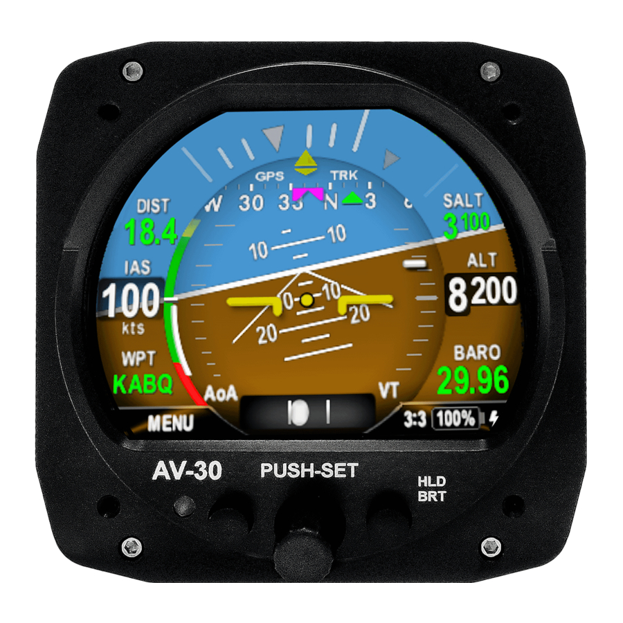
4 AV-30-E System Information 4.1 System Description The uAvionix AV-30-E is a fully digital multi-mode instrument that mounts in the legacy 3 1/8” round instrument panel. It can be field configured as either an Attitude Indicator (AI) or a Directional Gyro (DG) indicator. - Page 9 G-load display, and more are provided. An internal, rechargeable LiPo battery allows for operation for a nominal 2 hours in the event of aircraft power loss and 30 minutes minimum under all temperature conditions. UAV-1004233-001, AV-30-E Pilot’s Guide Revision A...
-
Page 10: System Functions
- GPS Navigator Route Line - Heading Bug Audio and Visual Alerting Functions: - AoA Alerting - G Limit Alerting - Excessive Roll Alerting Misc. Functions: - Internal Battery Operation Auto / Manual Brightness UAV-1004233-001, AV-30-E Pilot’s Guide Revision A... -
Page 11: Unit Interfaces
5 Unit Interfaces 5.1 Aircraft Systems Interfaces The following describes each of the AV-30-E system interconnects for both the AI and DG installation configurations. Note that some interfaces are optional and may not be available in a given installation. AV-30-E... -
Page 12: Power Input (Required)
This architecture allows the unit to continue operation if external power fluctuates or is completely lost. When external power is supplied to the AV-30-E, there is no mechanism to turn the unit off. When operating on battery, the unit may be forced off with a user interface action. -
Page 13: Pitot And Static Interfaces
OAT data is available as a textual data overlay and is used to compute temperature dependent data such as TAS and DALT. Each AV-30-E requires a dedicated probe and a single OAT probe cannot be shared between multiple units. UAV-1004233-001, AV-30-E Pilot’s Guide... -
Page 14: Audio Output (Optional)
Audio alerting is only supported when configured as an AI. 5.7 tailBeaconX Control (Optional) The AV-30-E has the option of being the transponder control interface for an installed tailBeaconX allowing the user to change the Mode and Squawk input to the tailBeaconX. -
Page 15: Ai Mode Display Components
The following section describes the user interface operations when operating as an AI. 6.2.1 AI Mode – Basic Components The following figure shows the basic AI with all customizable data overlay fields turned off. The data shown cannot be disabled or customized: UAV-1004233-001, AV-30-E Pilot’s Guide Revision A... - Page 16 Page Selection button (shown as page 1 of 3 in the figures above). A fourth, fully decluttered page allows all supplemental information to be hidden, leaving just attitude and slip displayed. UAV-1004233-001, AV-30-E Pilot’s Guide Revision A...
-
Page 17: Ai Mode - Attitude / Slip
6.2.3 AI Mode – Airspeed Indicator Indicated airspeed can be configured for display on the left side of the screen. The configured units (KTS or MPH) is displayed below the speed value. UAV-1004233-001, AV-30-E Pilot’s Guide Revision A... -
Page 18: Ai Mode - Flight Direction Indicator
6.2.4 AI Mode – Flight Direction Indicator The upper portion of the AI can be configured to display direction of flight in the form of either non-slaved DG (non-slaved heading) or GPS track. UAV-1004233-001, AV-30-E Pilot’s Guide Revision A... -
Page 19: Ai Mode - Baro Corrected Altitude Indicator
Figure 12 - AI Mode, Altitude Indicator The baro setting is adjusted utilizing the rotary knob. See Section 7.1- Push-Set Window for addition details. UAV-1004233-001, AV-30-E Pilot’s Guide Revision A... - Page 20 On the next power-up, this field elevation is utilized to reverse compute and estimated baro setting, potentially reducing the required adjustment amount required by the pilot. During this reverse computation process, the baro value will be shown in light grey. UAV-1004233-001, AV-30-E Pilot’s Guide Revision A...
-
Page 21: Ai Mode - Aoa Indication
See Section 11 - AoA Operation and Configuration for additional details on the AoA operation and setup. Pitch Angle Flight Path Angle Of Attack Level Ref Figure 14 – AoA Computation UAV-1004233-001, AV-30-E Pilot’s Guide Revision A... -
Page 22: Ai Mode - Vertical Trend Indicator
G, while those below represent less than 1.0 G levels. The scale markers will change color based on the G limits. See Section 9 - Alerts and Alert Limits for additional G limit alerting details. UAV-1004233-001, AV-30-E Pilot’s Guide Revision A... -
Page 23: Ai Mode - Text Fields
If a given parameter is invalid or currently unavailable, it will be presented as a dashed field. See Section 7.4 AI / DG Displayable Parameters for which parameters can be configured for display in these fields. UAV-1004233-001, AV-30-E Pilot’s Guide Revision A... -
Page 24: Dg Mode Display Components
GPS navigator and presented in the traditional HSI format: Bearing To & Heading Bug Display Mode (GPS Track) Course To Course Deviation Nav Mode (VFR Only) Fixed Deviation Scale ( 1 nmPer Dot) Figure 19 – GPS HSI Mode UAV-1004233-001, AV-30-E Pilot’s Guide Revision A... -
Page 25: Dg Mode - Gps Arc Mode
The following scales may be selected for display: Selectable Display Scales: 1, 2, 5, 10, 20, 50 and 100 nm All GPS deviation data is limited to VFR operations only, as indicated by the Nav Mode indication (“VFR”). UAV-1004233-001, AV-30-E Pilot’s Guide Revision A... -
Page 26: Dg Mode - Operational Aspects
The fourth page of both the AI and DG operating modes consists of a reversionary style display of just attitude and slip. This page / mode cannot be customized by the pilot. Figure 21 – AI/DG Fourth Page - Reversionary AI UAV-1004233-001, AV-30-E Pilot’s Guide Revision A... -
Page 27: Common Ui Operations
When non-slaved heading is configured for display Heading Bug When non-slaved heading or GPS track is configured for display Set Altitude When set altitude is configured for display Table 1 – Context Sensitive Push-Set Values UAV-1004233-001, AV-30-E Pilot’s Guide Revision A... -
Page 28: Brightness Menu
1 to 100 utilizing the rotary knob. When in automatic brightness mode, the display brightness is set automatically based on the bezel-mounted photocell. Pressing the DONE button will exit the Brightness Menu. UAV-1004233-001, AV-30-E Pilot’s Guide Revision A... -
Page 29: User Interface Customization
In general, is it suggested that the display be customized prior to flight, and that each page be setup for the different basic modes of flight operations (Departure, Enroute, Terminal) prior to actual flight operations. UAV-1004233-001, AV-30-E Pilot’s Guide Revision A... -
Page 30: Activating Customize Menu
Rotating the knob left and right will change the currently selected field. To edit the overlay value presented in the currently highlighted field, push the rotary knob. Figure 26 – UI Customization - Field Selection UAV-1004233-001, AV-30-E Pilot’s Guide Revision A... -
Page 31: Edit Presented Data
For example, airspeed will only be displayed on the left main area and altitude will only be displayed on the right side. Additionally, when operating in the DG mode, the available data displayed is different than when operating in the AI mode. UAV-1004233-001, AV-30-E Pilot’s Guide Revision A... -
Page 32: Dg Mode Customization
GPS arc presentation. The individual textual fields may also be selected and customized. All three pages of the DG can be customized in a similar manner. Figure 28 - DG Mode UI Customization UAV-1004233-001, AV-30-E Pilot’s Guide Revision A... -
Page 33: Ai / Dg Displayable Parameters
Vertical Speed Value Textual Set Altitude Textual Outside Air Temp Textual True Airspeed Textual Density Altitude Textual Direction Tape Graphical UAV-1004233-001, AV-30-E Pilot’s Guide Revision A... - Page 34 GPS Navigator Data Textual GPS HSI Indicator Graphical GPS Navigator Graphical Route Heading Bug Graphical Figure 29 - Data Overlay Types vs Operational Mode UAV-1004233-001, AV-30-E Pilot’s Guide Revision A...
- Page 35 • Press in the center knob • Press in the center knob to select a squawk digit • Press the right button to quick squawk 1200 • Press the left button (DONE) to finish UAV-1004233-001, AV-30-E Pilot’s Guide Revision A...
-
Page 36: User Interface And Font Style Options
ARIAL and LCD. These settings only effect the displayed colors and font style – all functional operations are identical regardless of the style settings. Figure 30 - UI Style Options UAV-1004233-001, AV-30-E Pilot’s Guide Revision A... -
Page 37: Alerts And Alert Limits
Table 2 - Alert Types and Priorities The thresholds for each alert are pilot adjustable, and each alert type can be independently enabled or disabled. Pressing the rotary knob when an alert is active will cancel the alert. UAV-1004233-001, AV-30-E Pilot’s Guide Revision A... -
Page 38: Internal Battery Operation
FAIL in red and no battery capability will be available. Figure 32 - Battery Fail Indication If the battery status shows FAIL, departure into actual or planned IFR conditions must not be performed. UAV-1004233-001, AV-30-E Pilot’s Guide Revision A... -
Page 39: Power Loss, Airspeed Above 40 Kts (In-Flight)
Figure 34 - Battery Charge Status It is normal for the battery charge icon to intermittently flash during battery charge cycle. 11 AoA Operation and Configuration UAV-1004233-001, AV-30-E Pilot’s Guide Revision A... -
Page 40: Operational Methodology
One of the main advantages of an AoA system is that it can provide an early indication of a stall, bringing enhanced awareness to the pilot. However, the AV-30-E system is supplemental in nature and does not replace the functionality provided by the aircrafts existing stall warning system. -
Page 41: Configured Limits
• A lower limit is configured to coincide with the AoA at which the aircraft flies under normal cruise conditions. This is typically on the order of 3 to 4 degrees. This visually correlates to the lowest one or two green bars on the AoA display. UAV-1004233-001, AV-30-E Pilot’s Guide Revision A... -
Page 42: Setting Aoa Upper Limit
• If the aircrafts stall-warning occurs after the indicator has reached the first red bar, the upper AoA limit needs to be numerically raised to coincide with the aircrafts stall-warning UAV-1004233-001, AV-30-E Pilot’s Guide Revision A... -
Page 43: Setting Aoa Lower Limit
• If no “green” bars are showing, the lower AoA limit needs to be numerically increased. • See the Setup Menu instructions and adjust the lower limit. • Repeat the above procedure as required. UAV-1004233-001, AV-30-E Pilot’s Guide Revision A... -
Page 44: Aoa Alert Types And Thresholds
In the following table, highlight the actual AoA presentation for the indicated phase of flight: Flap Setting Flaps Up Flaps Down Pre-Stall Climb Vx Climb Vy UAV-1004233-001, AV-30-E Pilot’s Guide Revision A... - Page 45 Cruise Best Glide Speed Approach 1.3 Vs 1.2 Vs 1.1 Vs Table 4 - AoA Observations UAV-1004233-001, AV-30-E Pilot’s Guide Revision A...
-
Page 46: Setup Menu
Pressing the knob when the desired field is shown will allow the associated setting to be adjusted. After adjustment, pressing the knob again will disable the editing mode. Pressing DONE will exit the Setup Menu. UAV-1004233-001, AV-30-E Pilot’s Guide Revision A... - Page 47 13 Install Menu Activation The install Menu should only be accessed on the ground. This Menu configures the AV-30-E after installation. For more information see the AV-30-E Installation Manual. To access the Install Menu, ensure the unit is turned off. Press and hold the main control knob in while power is applied.
- Page 48 Pressing the knob when the desired field is shown will allow the associated setting to be adjusted. After adjustment, pressing the knob again will disable the editing mode but the Install Menu will remain active. UAV-1004233-001, AV-30-E Pilot’s Guide Revision A...
- Page 49 9600, NMEA1 4800, NMEA1 9600, BEACON X Serial 2 Aux Serial Input Set to NONE Demo Mode Demo Mode Set to DISABLED Software Version Software Version For Reference Software Checksum Software Checksum For Reference UAV-1004233-001, AV-30-E Pilot’s Guide Revision A...
- Page 50 ± 20 kts G-Load Operational Range ± 8 g OAT Operational Range -40°C to +70°C OAT Accuracy ±4°C Bus Voltage Range 7 to 35 Volts Bus Voltage Accuracy ±1.0 Volt Table 6 - Operating Limits UAV-1004233-001, AV-30-E Pilot’s Guide Revision A...
Need help?
Do you have a question about the AV-30-E and is the answer not in the manual?
Questions and answers