uAvionix AV-30-C Installation Manual
Hide thumbs
Also See for AV-30-C:
- Instructions for continued airworthiness (22 pages) ,
- Service bulletin (24 pages) ,
- Manual (54 pages)
Table of Contents
Advertisement
Quick Links
Advertisement
Table of Contents

Subscribe to Our Youtube Channel
Related Manuals for uAvionix AV-30-C


Summary of Contents for uAvionix AV-30-C
- Page 1 AV-30-C Installation Manual UAV-1003947-001 Rev E...
- Page 2 retained.
-
Page 3: Revision History
AC 43.13-1B. Updated Top Level Assembly references. 6/3/2021 Software update to 2.1.2 Added Definition of Acronyms & Terms section 9/2/2021 Added requirement for pitot / static connection Add vibration check to System Checkout UAV-1003947-001, AV-30-C, Installation Manual Rev E... -
Page 4: Warnings / Disclaimers
2 Warnings / Disclaimers All device operational procedures must be learned on the ground. uAvionix is not liable for damages arising from the use or misuse of this product. This equipment is classified by the United States Department of Commerce's Bureau of Industry and Security (BIS) as Export Control Classification Number (ECCN) 7A994. -
Page 5: Limited Warranty
AV-30-C on the aircraft. For the duration of the warranty period, uAvionix, at its sole option, will repair or replace any product which fails in normal use. Such repairs or replacement will be made at no charge to the customer for parts or labor, provided that the customer shall be responsible for any transportation cost. -
Page 6: Table Of Contents
4 Table of Contents ................6 5 Introduction ..................8 5.1 Purpose ..................8 5.2 Definition of Acronyms & Terms ..........8 6 AV-30-C System Information ............9 6.1 System Description ..............9 6.2 System Functions ..............11 7 Certification ................... 13 7.1 Mechanical Instrument Replacement ........ - Page 7 13.2.6 EMC Checkout .............. 46 14 Troubleshooting ................. 48 15 Instructions for Continued Maintenance & Operation ....49 16 Aircraft Flight Manual Supplements..........49 17 Serial Interface Specification ............50 18 Field Update Capability .............. 51 UAV-1003947-001, AV-30-C, Installation Manual Rev E...
-
Page 8: Introduction
Maximum velocity in smooth air (never exceed). The red line at the top end of the ASI yellow arc. Minimum control airspeed with the critical engine inoperative Speed for best rate of climb OEI (single engine) UAV-1003947-001, AV-30-C, Installation Manual Rev E... -
Page 9: Av-30-C System Information
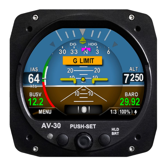
AV-30-C multi-mode instrument. System Description The uAvionix AV-30-C is a fully digital multi-mode instrument that mounts in the legacy 3-1/8” round instrument panel. It can be field configured as either an Attitude Indicator (AI) or a Directional Gyro (DG) indicator. It is fully self- contained with dual-precision inertial and pressure sensors and allows for a wide variety of pilot customization. - Page 10 2 hours in the event of aircraft power loss in flight and 30 minutes minimum under all temperature conditions. See AV-30-C Pilots Guide UAV-1003946-001 for additional details. UAV-1003947-001, AV-30-C, Installation Manual Rev E...
-
Page 11: System Functions
- GPS Navigator Route Line - Heading Bug Audio and Visual Alerting Functions: - AoA Alerting - G Limit Alerting - Excessive Roll Alerting Misc. Functions: - Internal Battery Operation - Auto / Manual Brightness UAV-1003947-001, AV-30-C, Installation Manual Rev E... - Page 12 Altitude 25,000 Feet (maximum) Optical Characteristics 3” Circular Diagonal Size Contrast Ratio (Typical) Brightness (Typical) 1000 cd/m Viewing Angle Left/Right 60° Viewing Angle Up 45° Viewing Angle Down 10° Backlight Lifetime (Typical) 50,000 Hours UAV-1003947-001, AV-30-C, Installation Manual Rev E...
-
Page 13: Certification
Title 14 of the Code of Federal Regulation (CFR) and other related accepted procedures. The certification basis for the AV-30-C is 14 CFR Part 23, Amendment 23- 61. Installation is approved as a Level A system and is robust to High Intensity Radiated Field (HIRF) and lightning levels applicable for both metallic and non-metallic aircraft. -
Page 14: Mechanical Instrument Replacement
Mechanical Instrument Replacement Approval is granted to replace legacy mechanical instrumentation as follows: • Installation of the AV-30-C (Dedicated AI mode) as the primary source for attitude and slip. Installation replaces the existing stand- alone vacuum or electrically powered attitude indicator. -
Page 15: Applicable Performance Standards
Applicable Performance Standards The AV-30-C was designed to, and satisfies, the applicable performance requirements defined in the following design standards: Table 2 - Applicable Performance Standards MOPS Title Category SAE AS8019 Airspeed Instruments Type B SAE AS392C Altimeter, Pressure Actuated, Sensitive... -
Page 16: Installation Limitations
• An electrical load analysis must be performed in association with the installation. • Connection to the Audio interface is not allowed for IFR approved non-metallic aircraft due to indirect lightning protection limitations. • A Wet compass must be installed in the aircraft. UAV-1003947-001, AV-30-C, Installation Manual Rev E... -
Page 17: Installation Locations & Operating Modes
CDI, HSI or flight director display. Reference CFR 23.1321 Arrangement and Visibility for additional FAA guidance on instrument installation location. UAV-1003947-001, AV-30-C, Installation Manual Rev E... -
Page 18: Operating Mode Configuration
Operating Mode Configuration The AV-30-C operating mode is configured during installation and can be set as follows: • Unit locked as a dedicated Attitude Indicator (AI Mode) • Unit locked as a dedicated Direction Indicator (DG Mode) • Unit unlocked; can be toggled between AI and DG mode by the pilot. -
Page 19: Functionality And Required Interfaces
Do not plug the pitot and static lines. Figure 3 – AV-30-C Aircraft Systems Interfaces – AI Mode Figure 4 - AV-30-C Aircraft Systems Interfaces – DG Mode UAV-1003947-001, AV-30-C, Installation Manual... -
Page 20: Feature Matrix
AoA Alerting Pitot / Static ✓ G Limit Alerting None ✓ Excessive Roll Alerting None Misc. ✓ ✓ Internal Battery Operation Pitot / Static ✓ ✓ Auto / Manual Brightness None UAV-1003947-001, AV-30-C, Installation Manual Rev E... -
Page 21: Power Input (Required)
Input range is compatible with both 12V and 24V aircraft. Each AV-30-C must have a dedicated, properly labeled, pilot resettable circuit breaker as part of the installation. Power for the unit should be supplied from the main battery master relay. It is recommended to shield the power wire. -
Page 22: Audio Output (Optional)
The GPS interface is an optional RS-232 serial input that is compatible with the industry standard “Aviation” output provided by most panel mounted GPS units, and NMEA serial interfaces provided by most hand-held GPS units. UAV-1003947-001, AV-30-C, Installation Manual Rev E... -
Page 23: Internal Magnetometer (Optional)
1. While AV-30-C is aligning, the unit will continue to battery mode if power is lost. Once aligned it will shut down. 2. If any button is pressed after power is lost, the AV-30-C will stay in battery mode. UAV-1003947-001, AV-30-C, Installation Manual... -
Page 24: Equipment Installation
Make sure that the caps have been removed from the back of the AV-30-C pitot and static ports. If the AV-30-C needs to be shut down after removing power, press and hold the left and right buttons until the unit shuts down. -
Page 25: Non-Supplied Components
The date of installation should be recorded in the aircraft’s log-book. Entry should include instrument(s) being replaced (AI or DG, or both), or, if the installation is being performed as a non-required instrument. Entry should also include a description of any optional connections made. UAV-1003947-001, AV-30-C, Installation Manual Rev E... -
Page 26: Mechanical Drawing
11.5 Mechanical Drawing Figure 5 – Mechanical Drawing UAV-1003947-001, AV-30-C, Installation Manual Rev E... -
Page 27: Mounting Screw Length Restriction
11.6 Mounting Screw Length Restriction The AV-30-C is fastened to the instrument panel with four 6-32 screws. The unit mounts from the rear of the instrument panel, with the screws being inserted from the front of the panel. The four 6-32 Mounting screws must observe depth limits given the internal component design. -
Page 28: Wiring Diagrams
11.7 Wiring Diagrams The AV-30-C performs different functions when installed as an AI or DG, and therefore wiring varies based on installation. Figure 7 and Figure 8 show connections for each configuration. The primary difference is that the DG does not support audio alerting. -
Page 29: Bonding Requirements
The following figure shows the grounding requirements for the electrical connections. The two D-Sub screws are to be utilized for shield and ground strap connections. The supplied ring terminal connectors are sized for these screws. UAV-1003947-001, AV-30-C, Installation Manual Rev E... - Page 30 The bond between the unit (measured at the D-sub screws) to the aircraft frame must be 2.5 milli-Ohms or less. D-SUB BACK-SHELL GROUND STRAP < 8” AIRCRAFT GROUND CABLE SHIELD DRAIN < 2.5” Figure 10 –Cable Shields and Ground Strap UAV-1003947-001, AV-30-C, Installation Manual Rev E...
-
Page 31: Unit Pinout
Reserved - Do Not Connect OAT Return Input White / Blue Probe Wire Reserved – Do Not Connect MFG Serial Output POWER GPS SERIAL AUDIO Figure 11 – Unit Connections – DB-15, Male (Rear Unit View) UAV-1003947-001, AV-30-C, Installation Manual Rev E... -
Page 32: Setup & Configuration
Operation in both AI and DG modes share common user interface controls as follows: TFT Color Display Left Push Button Right Push Button (Hold For Brightness Adjust) Photo Cell (Auto Screen Rotary Knob with Brightness) Momentary Push Figure 11 - Common User Interface Components UAV-1003947-001, AV-30-C, Installation Manual Rev E... -
Page 33: Available Menus
The edit fields menu allows the pilot to configure the display to show the various supplemental parameters in the desired locations. Details of this are covered in AV-30-C Pilots Guide UAV-1003946-001 and not addressed here. The Setup Menu allows the pilot to set various configurations and alerting limits as desired for the type of operations being performed. -
Page 34: Installation Menu
13 Installation Menu The installation menu is used to configure the AV-30-C after installation and should only be accessed on the ground and changed by the installer. To enable access the installation menu, ensure the unit is completely turned off. - Page 35 Figure 14 - Exiting Edit Mode Pressing DONE or a lack of user input for 30 seconds will exit the installation menu and return to the primary screen. Figure 15 - Setup Done / Exit Option UAV-1003947-001, AV-30-C, Installation Manual Rev E...
- Page 36 Software part number For reference SW VERSION Software version For reference SW CHECKSUM Software checksum For reference SW CERT Software certification For reference [AI] Available when Install Menu accessed through AI mode only Initial factory value UAV-1003947-001, AV-30-C, Installation Manual Rev E...
-
Page 37: Mandatory Settings
• Set the IAS units to match that of the existing airspeed indicator. • Set the Baro units to match that of the existing altimeter. • Set OAT units to owner / pilot preference. UAV-1003947-001, AV-30-C, Installation Manual Rev E... -
Page 38: Serial Inputs
– Do Not Enable unless authorized by BEACON X follow-on approval Autopilot adapter – Do Not Enable unless APA MINI authorized by follow-on approval • SERIAL 3 Set SERIAL 3 to NONE. Value Serial 3 Source UAV-1003947-001, AV-30-C, Installation Manual Rev E... -
Page 39: Aid Mode
(P/N UAV-1003429-002) then you will have a choice of NONE, MAG1, and MAG2. If the internal magnetometer is not found, only “NONE” will be displayed. Figure 16 - AID Mode Selection UAV-1003947-001, AV-30-C, Installation Manual Rev E... -
Page 40: Demo Mode
If power is removed from the unit while it is still aligning the unit will go to battery mode until it has completed the alignment process. Figure 17 - Aligning Annunciator If the indicator is not extinguished within 3 minutes, reference the troubleshooting section of this document for additional information. UAV-1003947-001, AV-30-C, Installation Manual Rev E... -
Page 41: Gyro Calibration
2.1.2 is displayed. Gyro Calibration must be completed on all units with software version 2.1.2 or later. 2. With the AV-30-C in the AI mode, enter the “Install Menu” page by pressing and releasing the left button repeatedly until the 3 menu is displayed. - Page 42 5. “Calibration in progress” will be displayed with a percentage complete. Figure 20 - Gyro Calibration Procedure 6. AV-30-C will indicate “Calibration successfully completed / Press DONE”. Press the left button under “DONE” and the calibration will be complete. If an error is shown, repeat the calibration process.
-
Page 43: Oat Interface
Pilot’s Guide to configure the display to show GPS navigational data in at least one textual display field. The image below shows a typical configuration that the pilot may setup. Figure 23 - GPS Data Elements UAV-1003947-001, AV-30-C, Installation Manual Rev E... -
Page 44: Vibration Check
The check procedure is performed during an engine run-up. 1. Before applying power to the AV-30-C, press and hold the center rotary knob and apply power. As the splash screen appears, check that a minimum version of 2.1.2 is displayed. - Page 45 • Replace worn engine mounts and address causes of high engine vibration. • Ensure the AV-30-C is not mounted in a location subject to high vibration. This can often be detected by placing your hand on various locations in the panel, and can be caused by poorly supported panel regions, adjacent equipment, or proximity to engine structure.
-
Page 46: Emc Checkout
After confirming all existing avionics are functioning properly, power off all existing equipment. Power on the AV-30-C and perform the following tests as they apply to the existing aircraft equipment. Observe load shedding procedures as appropriate for the aircraft during testing to ensure adequate power to complete the testing while maintaining enough reserve to support pre-flight and engine start. - Page 47 Operate the existing installed avionics according to manufacturer instructions. If capable, utilize the device transmit and receive functions through a range of values. Verify no errors, warnings, or unexpected operation is observed on the AV-30-C during operation of the installed avionics.
-
Page 48: Troubleshooting
Verify volume setting is sufficiently high in the Setup menu. Ensure alerting limits are configured as desired in the Setup Nuisance alerts are generated. menu. Disable any undesired alerting features in the Setup Menus. UAV-1003947-001, AV-30-C, Installation Manual Rev E... -
Page 49: Instructions For Continued Maintenance & Operation
• Visual Inspection Procedure • Altimeter Test and Calibration • Battery Test and Replacement Procedure 16 Aircraft Flight Manual Supplements See AV-30-C Flight Manual Supplement UAV-1004044-001 for normal, emergency and limitations as required by CFR §23.1581. UAV-1003947-001, AV-30-C, Installation Manual Rev E... -
Page 50: Serial Interface Specification
$GPRMB, Field 5 “L” Packet Bearing to Waypoint $GPRMB, Field 11 “Q” Packet Magnetic Variation $GPRMC, Field 10 “T” Packet, Flag 4 AT Master Flag $GPGGA, Field 6 “S” Packet, Flag 5 Garmin Master Flag UAV-1003947-001, AV-30-C, Installation Manual Rev E... -
Page 51: Field Update Capability
18 Field Update Capability The unit software can be field updated. Updating requires an in-line harness and Windows based PC. Contact uAvionix support for additional information, or reference available Service Bulletins. Figure 26 - Field Update Interface Diagram UAV-1003947-001, AV-30-C, Installation Manual...
Need help?
Do you have a question about the AV-30-C and is the answer not in the manual?
Questions and answers