Table of Contents
Advertisement
Quick Links
U S E R G U I D E
Software Version
3.4
Module:
Casia I
Module Model:
HCLM-0201
Camera Type:
8.9 MP USB
Camera Model
HEOC-0008
Ensuring no two aircraft collide mid-air.
uAvionix reserves the right to alter this document at any time without notice.
REVISION 1.1 | 2024-10-08
© 2024 uAvionix, Inc. All rights reserved.
Advertisement
Table of Contents

Related Manuals for uAvionix CASIA I


Summary of Contents for uAvionix CASIA I
- Page 1 Module Model: HCLM-0201 Camera Type: 8.9 MP USB Camera Model HEOC-0008 Ensuring no two aircraft collide mid-air. uAvionix reserves the right to alter this document at any time without notice. REVISION 1.1 | 2024-10-08 © 2024 uAvionix, Inc. All rights reserved.
-
Page 2: Trou Bles Hooting 1
C O N T E N T S Fe at u re s Ha rdwa re Compon ent s Insta llati o n Fli g ht De ck Confi g u ration Confi g u ration Man age ment Ve ri f i cat ion & Validation Autop i lots Gro un d Control St at ion s A D S - B Rece ivers... - Page 3 The world’s smallest, lightest, and lowest power Detect and Alert (DAA) solution for small UAS.
- Page 4 Features Detect & Avoid Senses non-cooperative aircraft using a patented computer vision and AI system. Integrated ADS-B Integrated ADS-B for increased coverage with cooperative aircraft. Collision Avoidance Avoid collisions with automatically executed, safe, drone maneuvers. Pilot-In-Command Report detected intruder aircraft to the ground-station and pilot-in-command in real time*. Low Size, Weight &...
-
Page 5: Safety First
It is your responsibility to maintain operations in accordance with local aviation regulations. uAvionix does not take on liability for your UAS operations, regardless of whether uAvionix technology is onboard or not. Before commencing any UAV operations, read the limitations and disclaimers section of this document to understand the importance of correct implementation, maintenance, and operation of Casia, and the potential impacts of external factors on its performance. -
Page 6: Hardware Components
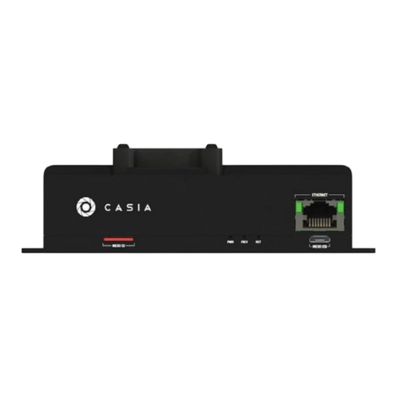
Hardware Components • 1x Casia Module • 1x 8.9 MP USB Camera Module • 1x Lens Cap • 1x USB 3.0 Type A to Micro B Screw-Locking Cable • 1x Pixhawk 2 Serial Cable • 1x Pixhawk 1 Serial Cable •... - Page 7 Casia I Module The Casia Module is the brains of the DAA system. This is where our software is executed and the cameras connect. It forms the central point of the Casia DAA system and interfaces between all sensors, autopilots, and other systems required to provide DAA capabilities.
-
Page 10: Camera Module
These two components are paired and optically calibrated at the time of manufacture and when taken apart require factory re-calibration. *Ensure camera and lens comply with uAvionix safety standards Note the white and red dots on the cameras and lenses below. If your system has such dots and they are not cracked or broken, this signifies that your camera and lens comply with the uAvionix safety standards. - Page 11 CABLES We provide all the cables that you need to use Casia, however sometimes it is necessary to use a different length cable or for the cable to be customized in another way. The cable diagrams, part numbers, etc are all provided in this section. Casia Power Cable...
- Page 12 Pixhawk 1 Serial Cable...
- Page 13 Pixhawk 2 Serial Cable...
- Page 14 Camera USB 3.0 Cable Additional cables are extremely difficult to make yourself. Please find these cables at the following suppliers: FLIR.com, Newnex.com...
-
Page 15: Installation
GPS receiver, etc) to avoid interference with that equipment. We recommend that Casia components are mounted away from antennas as well! Casia I Casia Module Find a suitable location for the Casia module to be located on your aircraft. As the heaviest component of the Casia system, it is best to mount this as near to the center of mass of the aircraft as possible. - Page 16 • In order to offload flight data, the ethernet port must be accessible to connect an ethernet cable to (shown in YELLOW) • There are status LEDs critical to pre-flight checks on the front of Casia that must be visible (shown in BLUE) •...
- Page 17 Camera When installing the camera in your aircraft, ensure that you first consider the following points about how the camera should be placed on the drone as there are some specific requirements to ensure that the DAA system functions correctly. •...
- Page 18 If at any point during installation you are unsure, please contact support@uavionix.com for assistance. In any integration position, no part of the ownship can occlude the field of view of any camera at any time during flight. Multi-rotor • Mounted to avoid having any of the rotors within the field of view •...
- Page 19 • Mounted to avoid having the propeller within the field of view • Camera is level with the airframe and facing forward to match autopilot orientation • Example image shows camera mounted on either one of the wings Helicopter • Mounted low on the body to ensure the rotors are not within the field of view •...
- Page 20 Power must be supplied to the Casia module within the specified acceptable input range. For Casia I this is an 11V to 40V supply. Make sure to reference the datasheet for your device and ensure that the power supply can provide an adequate power output to supply Casia.
- Page 21 Casia will power the camera from its internal power regulator systems so there is no need to connect power to the camera separately. The camera can be connected to either of the two USB ports indicated by the arrows in the image. The cables for the camera are standard USB 3.0 machine vision cables (these include locking screws), non machine vision cables will not include the locking screws.
- Page 22 A USB 3.0 machine vision cable is included in the Casia I kit, this cable has screw locking connectors at both ends that non machine vision cables will not have. Ensure that these cables are used and the screw locks are secured.
-
Page 24: Getting Started
In order to access FlightDeck you will need a user account. These are created and activated only for customers with an active Casia annual software license or license contract and are assigned at the time of purchase. Please contact support@uavionix.com if you require an account or account help. - Page 25 CASIA software updates It is vital that Casia remain updated with the latest version of the Flight Core software as uAvionix is constantly improving the performance of the DAA software, fixing issues and bugs, improving reliability, and adding important features and integrations.
-
Page 26: Checking For Updates
CHECKING FOR UPDATES To check to see if your device has an update available for it, navigate to the device page within FlightDeck for your device and check for a yellow colored alert on that page. This alert will give details of the current software installed on the device and any newer versions of software that are available. - Page 27 TOOLS FlightDeck provides many tools, this section explains the use of these tools and the data that they can provide. DATA UPLOAD & BACKUP Accessing Device Data Connect Casia to FlightDeck as described in the previous section, once this is complete navigate to the device page and follow these steps to assess how much data is available for upload on the device.
-
Page 28: Uploading Data
Uploading Data Connect Casia to FlightDeck as described in the previous section, once this is complete navigate to the device page and follow these steps. Navigate to the view page of the device that you have connected. Ensure that the device is online and shows “Connected” status. Click the “Upload Flight Data”... - Page 29 POST-FLIGHT ANALYSIS Flight Plotting The flight can be plotted using two different tools available in FlightDeck, these tools are the Path Plotted and Altitude Plotter. Each offers a different look at the flight from a 2D perspective. The Path Plotter shows a top-down view of the flight with the path of the drone and any intruders and maneuvers plotted along that path and laid on top of a map view of the area.
-
Page 30: Video Review
Video Review The video recorded by Casia is available once a flight is uploaded for your review. This may or may not be a continuous video clip of the entire flight, newer versions of the Casia FlightCore software do not record all the video during a flight in an effort to minimize the amount of data stored and therefore also transferred to FlightDeck. - Page 31 An example of a video playback in FlightDeck.
- Page 32 VIEW DETECTED INTRUDER DATA Intruder aircraft detected by Casia can be viewed in FlightDeck. To access intruder data for a flight: Connect your Casia device to FlightDeck (refer to FlightDeck → Getting Started → Setup). Uploaded the flight data to FlightDeck (refer to FlightDeck → Data Upload & Backup → Uploading Data).
- Page 33 A frame is taken from the camera when an intruder is detected. A blue bounding box is added post-flight during the batch process in FlightDeck to make it easier for a person to see where the intruder is. The blue bounding box represents the general area where the intruder is located.
- Page 34 DOWNLOAD INTRUDER AND TELEMETRY DATA Navigate to https://flightdeck.irisonboard.com/flights and select your flight from the list. Scroll to the bottom of Flight Details and click the Download Log Files button as shown below: You will be prompted to download a zip file of the flight logs. Download the file to your local device and extract it using a program like WinRAR.
-
Page 35: System Health
When assessing system health, uploads should show all of the status indicators as “YES” for a correctly integrated and functional system. If any “NO” messages are present, please contact uAvionix support at support@uavionix.com for further assistance in correcting the integration... -
Page 36: Additional Analysis
These detailed analysis tools require time from uAvionix to use and to generate a report, if you require these services please contact your account executive to arrange a detailed flight data analysis. - Page 37 Configuration Configuration of the Casia system is done through the FlightDeck which can be accessed at the following URL: https://flightdeck.irisonboard.com ADS-B PARAMETERS Parameter Description Value Default adsb__baud_rate The baud rate (data transfer Options: 57600 rate) of the ADS-B interface. 921600, 460800, 230400, 115200, 57600, 38400, 19200, 9600 adsb__serial_port...
- Page 38 AUTOPILOT PARAMETERS Parameter Description Value Default autopilot_interface_ The physical UART Options: Serial 2 address interface to use for autopilot Serial 2 or several other communication. UART and USB options autopilot_interface_ The baud rate (data transfer Options: 921600, 57600 baud_rate rate) of the autopilot serial 460800, 230400 interface.
- Page 39 COLLISION AVOIDANCE PARAMETERS Parameter Description Value Default avoid_vertical_dis- When aircraft are detected within this Units: Meters 304.8m tance vertical distance from the ownship, Greater than 0m avoidance will be initiatedif enabled. avoid_horizon- When aircraft are detected within this Units: Meters 3000m tal_distance horizontal distance from the ownship,...
- Page 40 COLLISION AVOIDANCE PARAMETERS Parameter Description Value Default avoid__coordi- The altitude reference used when Options: ATO, nate_frame conducting collision avoidance maneuver. AGL, AMSL, ATO: Relative altitude from take-off point. AGL: Above Ground Level altitude, requires laser altimeter or other ranging device integration with autopilot. AMSL: Above Mean Sea level altitude reference.
- Page 41 COLLISION AVOIDANCE PARAMETERS Parameter Description Value Default avoid__autore- Return the aircraft to autonomous flight Options: Disabled sume_enabled after a specified avoid_autoresume_ Enabled, timeout after an avoidance maneuver is Disabled triggered. This is misspelled as cas_send_resume_ manevuer in V0.21.2 avoid_autore- Duration of time since last detection of Units: Seconds sume_timeout intruder before mission is resumed.
-
Page 42: Camera Parameters
CAMERA PARAMETERS Parameter Description Value Default camera_pitch_angle The pitch angle that the camera is Units: 0 deg mounted on the drone relative to Degrees the autopilot XY plane. This is used for tuning the physical mount of the Greater than camera to the telemetry data provided -15 deg, less by the autopilot. - Page 43 DATA CAPTURE PARAMETERS Parameter Description Value Default data_capture__ When enabled, Casia will collect random Options: Enabled random_trigger_ data throughout the flight. Disable to Enabled, enabled minimize the flight data storage usage. Disabled data_capture__ Percentage of frames within the trigger Options: 100 10 Percent random_trigger_ window length that will send triggers.
-
Page 44: Detection Parameters
DETECTION PARAMETERS Parameter Description Value Default detection__classi- Selects which deep learning classifier Options: Stable fication_model model to use, a new preview model, or the Stable, stable release version. Preview detection__be- When enabled, allows detections below Options: Disabled low_horizon_en- the horizon. Enabled, abled Disabled... -
Page 45: Configuration Management
• Have the Device Manager user role Initial users for an organization are configured by the uAvionix Support Engineering team when a new Casia device is purchased. New users can be designed to have the above listed permissions and they should be carefully chosen and controlled by the organization in order to limit the access control of Casia devices to personnel who are authorized to have such access. -
Page 46: User Roles
User Roles Organization Administrator Organization Administrators have the following abilities and permissions. • View, create and manage users within the organization • View and manage all devices within the organization Device Manager Device Managers have the following permissions. • View and manage all devices within the organization Verification Configuration verification is performed using the configuration comparison tool within FlightDeck. - Page 47 When viewed side by side, two configurations can then be compared. Each configuration parameter is shown as it is configured within the selected configuration and any changes or differences between the two selected at the time are highlighted. In this example, the default configuration values for the device are compared with the values reported from the device at present.
- Page 48 Change Approval Changes to devices cannot be made without several steps which require the user to approve those changes before they are pushed to the device, the steps described here prevent users from accidentally changing configuration parameters without knowingly doing so. When making configuration changes to the device, the user must enter the device configuration tool page of the device management interface.
-
Page 49: Change Tracking
All changes are timestamped, the user that made the changes is logged, and the specific details of the configuration and the parameters is also logged. These logs are kept indefinitely once a device leaves uAvionix’s facility and is shipped to the customer for traceability. -
Page 50: Ground Testing
Verification & Validation The procedures in this section detail how an integration of Casia onto your aircraft is verified and validated for use in regular operations. These procedures and checks must be completed before Casia can be used for regular flight operations. -
Page 51: Data Review
By following the procedure in the previous section data is generated and logged by Casia that is used to determine the validation of this step. The data needs to be uploaded and inspected by an uAvionix Support Engineer in order to proceed further, please follow these steps to complete this step. - Page 52 Flight testing is performed to validate the following. Once this is completed it is possible for uAvionix rained personnel to give a final sign-off of the installation and for the Casia system to be used for regular operations. At this point the installation is complete! •...
- Page 53 SIGN-OFF Final sign-off on an installation is given by an uAvionix Support Engineer or a trained representative with the authorization of uAvionix to make this determination. Only once final sign-off has been received is the Casia system integration complete and can be used for...
- Page 54 Autopilots This section describes how to configure your autopilot to correctly support the Casia system. Ensure that you reboot the autopilot after changing these settings before flying the aircraft as some settings require a reboot before they take effect! ARDUPILOT BENEFITS Textual Alerts ArduPilot supports forwarding of text alerts from Casia to the Ground Control Station...
- Page 55 DAA functionality is no longer available. It may be required for some regulatory compliance reasons that this feature is supported, if this is the case please work with uAvionix support and regulations teams to determine the best course of action for your CONOPS.
- Page 56 CONFIGURATION Parameter Value Description SERIAL_X_BAUD Serial baud rate for the Casia connected serial port X (Where X can be 1, 2, 3, 4, or 5 for Pixhawk 2.1). Note that the value of 57 represents an actual baud rate of 57600. SERIAL_X_PROTO- MAVLink version used for serial port being used by Casia, replace X with the serial port being used...
- Page 57 CONFIGURATION (CONT.) Parameter Value Description Q_GUIDED_MODE Only applies to hybrid VTOL aircraft. This setting enables the use of VTOL mode (hovering) when in guided flight mode (as is the case during a collision avoidance maneuver). If this is not enabled, the aircraft will transition to forward flight when the avoidance maneuver is commanded! When enabled, the aircraft will always transition into VTOL...
- Page 58 PX4 please work with uAvionix support and regulations teams to determine the best course of action for your CONOPS.
- Page 59 CONFIGURATION (CONT.) Parameter Value Description MAV_X_RATE 7200 Configure the maximum sending rate for the MAVLink streams in Bytes/sec. If the configured streams exceed the maximum rate, the sending rate of each stream is automatically decreased. (7200 Bytes/s is 57600 bits/s divided by 8 bits/ Byte) SER_TELX_BAUD 57600...
- Page 60 PICCOLO BENEFITS LIMITATIONS Aircraft Location Indication The Piccolo autopilot by default does not support the ability for onboard equipment to transmit intruder aircraft location information to the ground control station without modification of the ground control station software. This means that positional information of detected aircraft intruders are not available to the ground control station operator.
- Page 61 UAV NAVIGATION Benefits, limitations and conguration information coming soon. Contact support@uavionix. com for details.
-
Page 62: Hardware Interface
The Piccolo autopilot uses an RS-232 serial interface to communicate with on-board equipment. Casia SR and Casia I are only equipped with a TTL UART serial interface and therefore must be used with a UART to RS-232 converter when configured with Piccolo. - Page 63 Piccolo hardware documentation. Interface: Payload/Serial TXD Pin: RXD Pin: GND Pin: Since there is a single connector on the Piccolo side, the customer is responsible for terminating the wires from the uAvionix cable harness to the Piccolo autopilot connector.
- Page 64 AVOIDANCE MANEUVER SPECIFICS The Piccolo autopilot does not have “modes” in the same way that the PX4 and Ardupilot autopilots do. Because of this, the way avoidance maneuvers are handled on Piccolo are different to the way that they are handled on the other two autopilots. This section details the specifics of how avoidance maneuvers have been implemented on the Piccolo autopilot without the ability to use modes.
- Page 65 Waypoint ID Name Description Default Maneuver This is the waypoint that the drone is directed to in order Waypoint to execute the configured collision avoidance maneuver according to the collision avoidance parameters. Resume This is the waypoint that the drone is directed to when Waypoint resuming a mission after the configured avoidance maneuver has been completed.
- Page 66 Exiting Avoidance Once the avoidance maneuver has been completed, the autopilot will be directed to resume the maneuver (if the resume feature is being used). If the autopilot_use_resume_maneuver parameter is set to true then the drone will go back to the resume waypoint (at the location where the avoidance happened) before going to continue on with the rest of the mission.
-
Page 67: Ground Control Stations
RPIC to notice and utilize in their decision making. This is in contrast to the alert display in some other ground control station software such as Mission Planner, because of this, QGroundControl is the preferred ground control station software that uAvionix recommends. - Page 68 An example of one of these alerts is shown below. Additionally these alerts are converted to speech by the software and provide an auditory warning. USAGE Intruder Display When intruder aircraft are detected by Casia they will be forwarded to the autopilot. The autopilot then sends this information to the ground control station for display to the remote pilot.
- Page 69 QGroundControl also displays the callsign of the intruder and the MSL altitude of the intruder below the icon in small white text. Note that the callsign “VISION” is used by Casia when communicating intruders detected using the vision system.
- Page 70 Avoidance Maneuver When an avoidance maneuver is issued by Casia, the RPIC is alerted to this by the mode change of the autopilot which is displayed within the ground control station software and can additionally be configured to be an auditory alert. The autopilot mode is displayed within the top bar of the QGroundControl interface, as shown in the images on the right the mode changes from when the avoidance...
- Page 71 Mission Planner Mission Planner is commonly used as the primary ground control station for the ArduPilot autopilot software. LIMITATIONS Alerts During flight Casia generates several alerts that must be displayed to the RPIC for safety, situational awareness, and sometimes regulatory compliance reasons. Mission Planner implements these alerts as a small textual output hidden in a sub-tab of the user interface and displayed amongst other output messages from the autopilot during flight.
- Page 72 An example of one of these alerts is shown on the right in the red text in the Heads Up Display as well as the small white text on the bottom left. Note: Alerts showing up in Mission Planner are dependent on the version of Mission Planner.
- Page 73 Mission Planner also displays the callsign of the intruder if the intruder icon is clicked on in the user interface. Note that the callsign “VISION” is used by Casia when communicating intruders detected using the vision system.
- Page 74 Avoidance Maneuver When an avoidance maneuver is issued by Casia, the RPIC is alerted to this by the mode change of the autopilot which is displayed within the ground control station software and can additionally be configured to be an auditory alert. The autopilot mode is displayed within the heads up display of the Mission Planner interface in the bottom right of this UI section in white test, as shown in the images on the right the mode changes from...
- Page 75 APM Planner is officially supported by the ArduPilot community however is untested by uAvionix due to its low usage within the industry. While it is likely that many features that MissionPlanner implements are also supported on APM Planner, it is not supported by...
- Page 76 The serial UART port in Casia I is reserved for the autopilot. To leverage a uAvionics PingRX ADS-B receiver with Casia I, plug it into the 2nd USB port. You will need a serial UART to USB cable. If necessary, uAvionix can provide a cable of the desired length (contact support@ uavionix.com), or you can obtain/manufacture the cable independently.
- Page 77 OPERATING INSTRUCTIONS Collision Avoidance Behavior Physical Avoidance Maneuver Casia uses a standardized avoidance maneuver for all intruder encounter scenarios. This maneuver has been validated through simulation and flight testing to provide the best balance between simplicity and ease of implementation and support by different autopilots, as well as maximizing the ability to maintain separation between the drone and the intruder aircraft.
- Page 78 Airframe Type Maneuver Fixed-Wing Descending right hand turn loiter May vary depending on Autopilots support, flight mode, and configuration Fixed-Wing VTOL Descending right hand turn loiter May vary depending on Autopilots support, flight mode, and configuration Multi-Rotor Stop, descend, and loiter Helicopter Stop, descend, and loiter...
- Page 79 Casia uses a computer vision system as the primary means of cooperative and non- cooperative aircraft detection but can also process and use intruder data from ADS-B information received by the autopilot (e.g. from sensors such as the uAvionix Ping). ENTERING AVOIDANCE When intruders are detected the GCS will immediately be notified via the Autopilot.
- Page 80 GCS connection loss, and to work around the inherent un-reliability and delay of requiring human input in fast-paced and uncertain environments. The GCS operator is then notified that an avoidance maneuver has taken place by monitoring the mode of the autopilot. When avoiding a collision the autopilot will switch into the mode used by Casia for avoidance as defined by the following table.
- Page 81 The complete flow-chart for initiating an avoidance maneuver is displayed below.
- Page 82 EXITING AVOIDANCE Manual The remote pilot may exit the avoidance maneuver at any time and continue the mission by switching the aircraft back into another flight mode such as “Auto” or “ Fly-By-Wire ”. Note that if you have enabled the automatic mission resume described below, it is possible that Casia will command the autopilot to go into “Auto”...
- Page 83 Once the timeout elapses, Casia will send a command to the autopilot to switch back into autonomous mode and continue on to the last waypoint that was previously being targeted before the avoidance maneuver was initiated (note that for some autopilots this behavior must be set in the autopilot configuration, please see the Autopilots section in the user guide for detailed information).
- Page 84 The complete flow-chart for exiting an avoidance maneuver automatically is displayed below. Note that if an intruder is detected immediately after resuming a mission, this is treated as if a new avoidance maneuver is being initiated, please see the section above on the behavior that would occur.
-
Page 85: Safety Interlocks
Safety Interlocks Casia will engage an avoidance maneuver only when of the following criteria have been met. The drone is above a preset, autopilot-reported, altitude known as the “ Minimum Maneuver Altitude ” present in the Casia system Configuration . The drone is in autonomous mission flight mode, as defined by the following table. -
Page 86: Safety Limits
Safety Limits When initiating a maneuver, Casia has certain limitations on its behavior that prevent unwanted behavior by the avoidance maneuver function. It will not command a descent below a specified “ Minimum Maneuver Clearance ” altitude which is present in the Casia system Configuration , even if this would result in an altitude change of less than the programmed altitude change parameter. -
Page 88: Alert Behavior
Alert Behavior Only ArduPilot autopilots forward the required message to the Ground Control Stations at this time. Therefore only ArduPilot autopilots currently support these alerts. ALERT : “Collision avoidance active” Description The system detected an intruder within the avoidance boundary and will execute an avoidance maneuver. - Page 89 ALERT “Do manual avoid immediate, auto disable” Description The system detected an intruder within the avoidance boundary, but the system will not execute an avoidance maneuver (this could because avoidance is disabled, its already in avoidance, its below safe altitude, etc. If it can’t avoid for some reason, it this message indicates it detects an intruder but will not direct the autopilot to do anything).
- Page 90 ALERT “Aircraft at safe distance, small plane/helicopter” Description The system detected an intruder, but it is outside of the avoidance area, so no maneuver will execute since its at a safe distance Will be sent a maximum of every 30 seconds while the intruder is still detected and remains outside the avoidance boundary.
- Page 91 ALERT “Casia: Node Degradation Detected, Reboot Pending” Description The watchdog has detected that a node is down based on missing heartbeats and that a reboot is pending. Indicates the system is going to reboot soon. Will be sent a maximum of every 10 seconds until the system reboots or resumes full functionality.
- Page 92 ALERT “Casia: All nodes are Operational” Description All expected nodes are sending heartbeats to the watchdog. This will show up initially after boot once the watchdog has received a heartbeat from all nodes it is monitoring. It will also show up if a node is perceived to go down, then able to recover itself somehow. Once the node is thought to be down, the status is changed in the system (usually indicated by the above reboot pending message).
- Page 93 Watchdog Behavior Watchdog system Casia includes a Watchdog System that allows it to detect and recover from errors while in operation. The way this system is designed and functions is described in this document. The Casia watchdog system works on the basis of continued positive affirmation of functionality and time-outs to detect failures within the system.
- Page 94 Software Watchdog The software watchdog functions by monitoring heartbeats from each individual component of the software on Casia. These heartbeats constantly confirm to the Software Watchdog that each component is still functional. If everything is still considered function, the Software Watchdog will send heartbeats to the Hardware Watchdog (see the next section of this document) to confirm that the software system in Casia is healthy.
- Page 95 Once a timeout occurs the heartbeats to the Hardware Watchdog will immediately stop being sent (which begins the Hardware Watchdog timeout) and the recovery action of the Software Watchdog is executed. This will exit and re-launch the entire Casia software stack to clear out any potential issue and start from a clean beginning.
- Page 97 Hardware Watchdog The Hardware Watchdog functions by monitoring for software stack functionality by listening to the heartbeats from the Software Watchdog as described in the previous section. The Hardware Watchdog is a completely independent hardware and software from the main Casia processor and is able to therefore independently monitor the performance of Casia and recover the system from potential underlying hardware or system level failures the Software Watchdog cannot recover the system from.
- Page 98 The specific time-outs are listed here: Timeout Duration Software Watchdog Heartbeat (before indication) Software Watchdog Heartbeat (before reset) Hard Reset Initialization Wait...
-
Page 100: Led Indicators
LED Indicators System Indication Hardware Solid On Watchdog • Ready for Flight • Receiving heartbeats from Software Watchdog to Hardware Watchdog Slow Blink • Booting Up/Initialization wait time Fast blink • Error, lost heartbeats from Software Watchdog • Will reset after timeout finished Software Solid On •... -
Page 101: Preflight Checklist
Pre-flight Checklist The following checks must be performed before flight to ensure that the Casia system is functioning correctly. If any of these checks fail, the issue must be corrected and the checklist started again. System Configuration Login to FlightDeck and connect Casia to FlightDeck Check the Casia device history log to ensure no un-desired changes have been made Confirm that the software version on Casia is as desired... - Page 102 “heartbeat” blinking pattern to indicate correct operation. If this is the case please contact support@uavionix.com to update your software! In versions of Casia Flight Core software before V1.0 LED C has no function. Please update your software as described in the FlightDeck.
-
Page 103: Camera Status
Camera Status LED on the back of the camera body is solid and not flashing in any way LED on the back of the camera body is green in color System Status GCS has received the “Casia: All nodes are operational” message... -
Page 104: In-Flight Procedures
In-Flight Procedures Detection Detection of crewed aircraft intruders is done on-board the aircraft by the FlightCore running on Casia. These detections are made within the images from the camera, however the detection system is then able to output the 3D position of the intruder aircraft to additional systems down-stream which are used for the Alert and Avoid functionality described further in this article. - Page 105 Note that the language used in the alerts generated by Casia are compliant with FAA Advisory Circular AC 25.1322-1, however Ground Control Station software support for other aspects of this advisory may vary. Note that Casia will only send the same type of alert once every 30 seconds.
- Page 106 Detection Alert As soon as an intruder is detected by the computer vision system a Detection Alert will be sent if that intruder is outside of the Avoidance Distance, if it is within that distance then an immediate Breach Alert will be sent instead, please see the following section for details on that alert.
- Page 107 Avoidance Intruder aircraft avoidance is initiated by Casia automatically to ensure timely and effective maintenance of airspace separation between the drone and the intruder crewed aircraft. The specifics of the maneuver are notified to the PIC and GCS operator at the time the avoidance takes place to ensure they are informed of the change in the flight characteristics of the drone.
-
Page 108: Post Flight Checklist
Post-Flight Checklist The following checks must be performed after a flight to ensure that the Casia system remains correctly functional once the drone has landed. Lens The anti-tamper paint on the lens is not cracked or damaged in any way Inspect the lens for dust, particulates, liquids, fingerprints, or other blemishes Clean the lens with a microfiber cloth and lens cleaning fluid... - Page 109 In older Casia devices the Hardware Watchdog status indicator (LED A) will show a “heartbeat” blinking pattern to indicate correct operation. If this is the case please contact support@uavionix.com to update your software! In versions of Casia Flight Core software before V1.0 LED C has no function. Please update your software as described in the FlightDeck.
-
Page 110: Maintenance Plan
Maintenance Plan uAvionix recommends its users to incorporate regular maintenance of Casia into their internal maintenance schedule to ensure the system continues to operate at its peak performance. Provided below are the recommended maintenance actions to be made at different intervals and an explanation of each of these procedures. -
Page 111: Before Beginning
25 Flight Hour interval CLEANING This is done to remove any built up particulate that may ingress into the body of the system over time and to make it easier to perform the inspections required for the 25 hour maintenance. Special care should be taken on the lens of the camera to ensure the lens is completely free of any particulate that may have a detrimental affect on the quality of imagery and performance of the system. - Page 112 Cables with thumbscrews should be snugly tightened. Cables to be checked include the power, autopilot, camera, and fan cables. Contact the uAvionix support team to replace any worn or damaged cabling.
-
Page 113: Software Update
Software Update process, and LED lights may not be displayed for a period of time. FlightDeck will indicate when the update is complete. FOLLOW-UP Should there be evidence that the system has failed any of these checks contact the uAvionix support team at for assistance before flying again. - Page 114 50 Flight Hour interval CLEANING This is done to remove any built up particulate that may ingress into the body of the system over time and to make it easier to perform the inspections required for the 25 hour maintenance. Special care should be taken on the lens of the camera to ensure the lens is completely free of any particulate that may have a detrimental affect on the quality of imagery and performance of the system.
- Page 115 Cables with thumbscrews should be snugly tightened. Cables to be checked include the power, autopilot, camera, and fan cables. Contact the uAvionix support team to replace any worn or damaged cabling.
-
Page 116: Assembly Check
4 which take a M1.5 hex driver. Any screws that are loose should be re-secured with Loctite 242 threadlocker (blue) and any screws that may be missing can be replaced by contacting the uAvionix support team. Before Beginning Prepare an M1.5 hex screwdriver... - Page 117 Procedure Gently torque the 4x screws securing the fan in place to ensure they are snug (shown in GREEN) Gently torque the 4x screws on the top of the Casia enclosure, between the heat sink fins, to ensure they are snug (shown in RED) Gently torque the 2x screws securing the IO board in place, on the front of the device, to ensure they are snug (shown in YELLOW)
- Page 118 Gentle pressure should be placed on each connector to validate that it is still firmly seated on its respective board. If any connector appears to be loose, contact the uAvionix support team for assistance. Before Beginning...
- Page 119 In order to assess that the camera is still in focus, some footage from the camera must be assessed against a standard camera calibration target by uAvionix. This check is extremely important and must be completed at regular intervals to ensure the Casia DAA system is still functioning correctly.
- Page 120 Casia as well as fixing bugs and making improvements to features. We advise that when performing maintenance that the latest version of software available for your device is downloaded and updated to.
- Page 121 FOLLOW-UP Should there be evidence that the system has failed any of these checks contact the uAvionix support team at for assistance before flying again. support@uavionix.com To arrange maintenance, please contact the uAvionix support team at support@uavionix.com.
-
Page 122: Troubleshooting
The power source is capable of delivering the required power for Casia (15W maximum draw, therefore >15W is recommended). If none of these are the issue, there may be an internal malfunction to the Casia device due to corrosion, extreme vibration, wear, defect, or other causes. Please contact uAvionix support for assistance. -
Page 123: Cooling Fan
Make sure that the fan has not been subjected to water or other liquids by checking for stains or other residue. If there are signs of damage or the above checks are completed without issue contact uAvionix support and a replacement fan can be sourced. WATCHDOGS LED A STUCK IN FAST BLINK This indicates that there is a persistent error detected by the Casia hardware watchdog. - Page 124 Note: In older Casia devices the Hardware Watchdog status indicator (LED A) will show a “heartbeat” blinking pattern to indicate correct operation. • Please ensure that all the system configuration parameters are set correctly for external devices such as the ADS-B receiver, Camera, and Autopilot. •...
- Page 125 Ensure the cables between Casia and the autopilot are un-damaged and are correctly connected (See Casia Datasheet or Casia I Datasheet for connector pinouts). Through FlightDeck, check that the Casia autopilot settings are correctly configured for your autopilot (See Casia configuration section of this document)
-
Page 126: Flight Behavior
FLIGHT BEHAVIOR MANEUVER NOT EXECUTED If a maneuver is not executed during an encounter with an intruder aircraft this may be because of many reasons. Please follow this checklist to ensure that Casia is functioning correctly. Camera Problems: • The lens cap was removed during flight. •... - Page 127 Please ensure that all system configuration settings are to your liking for the desired avoidance maneuver outcome and reference the descriptions of these settings and parameters in this document. If these settings are not clear please contact uAvionix Support for additional assistance.
-
Page 128: Further Assistance
The correct autopilot type is configured in the Casia system configuration. • The autopilot cable and connector are not damaged, are properly seated, and fixed. • The autopilot parameters are set correctly to forward MAVLink messages to the groundstation. FURTHER ASSISTANCE Please contact uAvionix support for further assistance at support@uavionix.com. - Page 129 Casia I has been trained and tuned to identify and classify small GA aircraft. The specified results are specific to the detection of small GA aircraft (small planes and helicopters). Casia I will not perform to the above level when the intruder aircraft are small drones.
- Page 130 Reliability / average uptime of the Casia System is under evaluation. Casia should be rebooted between flights to maximize performance. Following a heavy crash or impact, your Casia system should be replaced or returned to uAvionix for evaluation and repair.
- Page 131 Ensuring no two aircraft collide mid-air. uAvionix reserves the right to alter this document at any time without notice. uAvionix Inc. 300 Pine Needle Lane, Bigfork, MT. 59911 USA. © 2024 uAvionix, Inc. All rights reserved.
Need help?
Do you have a question about the CASIA I and is the answer not in the manual?
Questions and answers