
Related Manuals for AEMC PEL 52


Summary of Contents for AEMC PEL 52
- Page 1 User Manual ENGLISH Power & Energy Logger Model PEL 52 POWER & ENERGY LOGGER WITH AEMC INSTRUMENTS ®...
- Page 2 Copyright Chauvin Arnoux , Inc. d.b.a. AEMC Instruments. All rights reserved. © ® ® No part of this documentation may be reproduced in any form or by any means (including electronic storage and retrieval or translation into any other language) without prior agreement and written consent from Chauvin Arnoux , Inc., as governed by United States and International copyright laws.
- Page 3 Statement of Compliance Chauvin Arnoux , Inc. d.b.a. AEMC Instruments ® ® certifies that this instrument has been calibrated using standards and instruments traceable to international standards. We guarantee that at the time of shipping your instrument has met the instrument's published specifications.
-
Page 4: Table Of Contents
TABLE OF CONTENTS 1. INTRODUCTION...............7 1.1 PRECAUTIONS FOR USE .............. 8 1.2 RECEIVING YOUR SHIPMENT ............. 8 1.3 ORDERING INFORMATION ............11 1.3.1 Accessories................11 1.3.2 Replacement Parts ..............11 1.4 CHARGING THE BATTERY ............12 2. PRODUCT FEATURES ............13 2.1 DESCRIPTION ................13 2.2 INSTRUMENT FRONT PANEL ............ - Page 5 4.2 RECORDING ................. 34 4.3 MEASURED VALUE DISPLAY MODES ........34 4.3.1 Measurement Mode ............35 4.3.2 Energy Mode ..............37 4.3.3 Maximum Mode ............38 5. PEL CONTROL PANEL - DATAVIEW ........41 ® 5.1 INSTALLING DATAVIEW .............41 ® 5.2 PEL CONTROL PANEL ..............45 6.
- Page 6 7. MAINTENANCE ..............60 7.1 CLEANING ..................60 7.2 BATTERY ..................60 7.3 UPDATING FIRMWARE ..............61 7.4 REPAIR AND CALIBRATION ............61 7.5 TECHNICAL AND SALES ASSISTANCE ........62 7.6 LIMITED WARRANTY ..............62 7.6.1 Warranty Repairs ..............63 8. APPENDIX ................64 8.1 MEASUREMENTS .................
-
Page 7: Introduction
Example: hardwired equipment in fixed installation and circuit breakers. CAT II corresponds to measurements performed on circuits directly connected to the electrical distribution system. Example: measurements on household appliances and portable tools. Power & Energy Logger Model PEL 52 - User Manual... -
Page 8: Precautions For Use
Save the damaged packing container to substantiate your claim. Power & Energy Logger Model PEL 52 - User Manual... - Page 9 (1) Safety Sheet for the PEL (1) Safety Sheet for the MiniFlex Sensors ® (1) Compliance Sheet (1) SD Card (1) Quick Start Guide (2) AAA Rechargeable Batteries (1) Battery Information Sheet Power & Energy Logger Model PEL 52 - User Manual...
- Page 10 Cat. #5000.14 Dataview ® Software Also Included: (1) Safety Sheet for the PEL (1) Compliance Sheet (1) SD Card (1) Quick Start Guide (2) AAA Rechargeable Batteries (1) Battery Information Sheet Power & Energy Logger Model PEL 52 - User Manual...
-
Page 11: Ordering Information
CAT IV 15 A, UL for PowerPad & PEL Series ......Cat. #2140.44 Set of 12, color input ID markers for the PowerPad Series ..Cat. #2140.45 USB SD - card adapter for PEL 102, PEL 103 & PEL 52 ..Cat. #5000.45 Order Accessories and Replacement Parts Directly Online Check our Storefront at www.aemc.com/store... -
Page 12: Charging The Battery
When the symbol is full and steady, the battery is fully charged. NOTE: The battery will take approximately 5 h to fully charge. Power & Energy Logger Model PEL 52 - User Manual... -
Page 13: Product Features
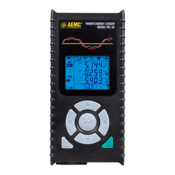
2. PRODUCT FEATURES 2.1 DESCRIPTION The Power & Energy Logger Model PEL 52 is an easy-to-use, single-phase, and two-phase Power and Energy Logger. The instrument has a large, backlit LCD display for crisp viewing and an SD card to store measurements. Designed to operate in 600 V CAT III or lower environments, the PEL records voltage, current, power, and energy on alternating current distribution networks (50 Hz or 60 Hz). -
Page 14: Instrument Front Panel
NOTE: Before connecting a current sensor, consult the sensor's corresponding safety data sheet or user manual. Also, the PEL must not be used when the SD card slot is open. Power & Energy Logger Model PEL 52 - User Manual... -
Page 15: Instrument Rear Panel
SD card facing up and forward, gently push card straight into the card slot until you hear a click. SD Card Slot Screw Protective Cover Figure 6 Power & Energy Logger Model PEL 52 - User Manual... -
Page 16: Mounting
In select mode, starts or stops a recording after the Select button is pressed. It also allows the type of Wi-Fi to be chosen. Table 1 If any button is pressed, the backlight will turn on for 3 minutes. Power & Energy Logger Model PEL 52 - User Manual... -
Page 17: Lcd Display
PEL Control Panel. 5. Wi-Fi Direct ON (steady): Wi-Fi Direct is enabled and not transmitting. Blinking: Wi-Fi Direct is actively transmitting. OFF: Wi-Fi Direct is disabled. Power & Energy Logger Model PEL 52 - User Manual... - Page 18 For more information reference the Help File. 10. Battery Empty : The battery must be charged. Partially filled : The battery is partially charged. Filled : The battery is fully charged. Blinking: The battery is charging. Power & Energy Logger Model PEL 52 - User Manual...
-
Page 19: Memory Card
PC. Insert the new SD card. Press it in all the way until you hear a click (see § 2.5). ■ Close the SD card protective cover. ■ Power & Energy Logger Model PEL 52 - User Manual... -
Page 20: Setup
This is a precaution intended to prevent a recording from being unintentionally stopped by the user. To turn the PEL off: Disconnect the PEL. ■ Press and hold the ON/OFF button until the device turns off. ■ Power & Energy Logger Model PEL 52 - User Manual... -
Page 21: Battery Operation
1P-2W1I: Single-phase 2-wire with a current sensor ■ 1P-3W2I: Single-phase 3-wire (2 voltages in phase) with two current sensors ■ 2P-3W2I: Two-phase 3-wires (2 voltages in opposite phases) with two current ■ sensors Power & Energy Logger Model PEL 52 - User Manual... -
Page 22: Wi-Fi
■ WIFI ST. PUSH ENTER FOR WIFI ST, WIFI OFF. PUSH ENTER FOR WIFI OFF or WIFI AP. PUSH ENTER FOR WIFI AP. Figure 10 Figure 11 Power & Energy Logger Model PEL 52 - User Manual... - Page 23 ■ Figure 12 Start the PEL Control Panel (see § 5). ■ Go to Instrument, Add an Instrument, PEL 52, to Wifi access point. ■ When you are connected to the PEL Control Panel, you will be able to: ■...
- Page 24 Your device will connect to this Wi-Fi network. ƒ The Wi-Fi access point connection will be lost. ƒ Once the PEL is connected to the network, you can find the PEL's IP ƒ address in information mode Power & Energy Logger Model PEL 52 - User Manual...
- Page 25 Configuration of the DataViewSync™ connection To connect the PEL to DataViewSync™, the PEL must be in WIFI ST, ■ and the connected network must have internet access in order to access DataViewSync™. Power & Energy Logger Model PEL 52 - User Manual...
-
Page 26: Nominal Primary Current
■ ■ If two current sensors are connected, they must be identical. For AmpFlex or MiniFlex sensors, press the button to select 300 A or 3000 A. ■ ® ® Power & Energy Logger Model PEL 52 - User Manual... -
Page 27: Aggregation Period
From the aggregation period screen, press the ▼ key to access the following ■ screen. Figure 18 To reset the device to the default Wi-Fi configuration (direct Wi-Fi, password ■ deleted), press the key. Power & Energy Logger Model PEL 52 - User Manual... -
Page 28: Remote User Interface
■ menu (see § 3.4). The following screen will be displayed: Figure 19 NOTE: Refreshing the display is not automatic. You need to do this regularly. Power & Energy Logger Model PEL 52 - User Manual... - Page 29 On the second tab, measurements can be viewed: Figure 20 On the 3rd tab, the device information is displayed: Figure 21 Power & Energy Logger Model PEL 52 - User Manual...
-
Page 30: Information
To enter Information mode, press the ◄ or ► buttons until the symbol is ■ selected. Using the ▲ and ▼ keys, scroll through the device information: ■ ■ Type of network Power & Energy Logger Model PEL 52 - User Manual... - Page 31 Year, month, day ■ Time Hour, minute, second ■ IP address (scrolling) ■ Firmware version and scrolling serial number After configuration is complete, the instrument is ready for use. Power & Energy Logger Model PEL 52 - User Manual...
-
Page 32: Operation
Connect the V1 measuring lead to the L1 phase conductor. ■ Connect the I1 current sensor to the L1 phase conductor. ■ 600 V 600 V CAT III Figure 23 Power & Energy Logger Model PEL 52 - User Manual... -
Page 33: Single-Phase 3-Wire 2-Currents: 1P-3W2I
Connect the I1 current sensor to the L1 phase conductor. ■ Connect the I2 current sensor to the L2 phase conductor. ■ 600 V 600 V CAT III Figure 25 Power & Energy Logger Model PEL 52 - User Manual... -
Page 34: Recording
The displays can be accessed as soon as the PEL is turned on but the values will be zero. The values will update when voltage or current is present at the inputs. Power & Energy Logger Model PEL 52 - User Manual... -
Page 35: Measurement Mode
Single-phase 2-wire (1P-2W1I)v φ (I If the current sensor is not detected, all the quantities that depend on the current (current, angle, powers, PF) are undefined (displays Power & Energy Logger Model PEL 52 - User Manual... - Page 36 Sum of powers on L1 and L2. If a current sensor is not detected, all the quantities that depend on this current (current, angle, powers, PF) are undefined (displays Power & Energy Logger Model PEL 52 - User Manual...
-
Page 37: Energy Mode
Es+: Total apparent energy consumed (by the load) in VAh ■ Es-: Total apparent energy supplied (by the source) in VAh ■ NOTE: The device does not display the “h” symbol. Therefore, you will see “W” for “Wh”. Power & Energy Logger Model PEL 52 - User Manual... -
Page 38: Maximum Mode
Single-phase 2-wire (1P-2W1I) Power & Energy Logger Model PEL 52 - User Manual... - Page 39 Single-phase 3-wire 2-currents (1P-3W2I) and two-phase 3-wire (2P-3W2I) Sum of powers on the load on L1 and L2. Power & Energy Logger Model PEL 52 - User Manual...
- Page 40 Sum of powers on the source on L1 and L2. Power & Energy Logger Model PEL 52 - User Manual...
-
Page 41: Pel Control Panel - Dataview
Setup.exe file located in the ® root directory of the USB drive, and double-click it to run the installation program. 3. The DataView setup screen appears. ® Figure 26 Power & Energy Logger Model PEL 52 - User Manual... - Page 42 4. Select the language version of DataView you want to install (English, ® French, or Spanish) then click Next. (By default, the language selected in step 3 is highlighted.) Figure 27 Power & Energy Logger Model PEL 52 - User Manual...
- Page 43 6. The Setup program now informs you that it is ready to install DataView ® If you want to review any of your previous selections, click the Previous button to return to earlier screens. Otherwise, click Install to begin installation. Power & Energy Logger Model PEL 52 - User Manual...
- Page 44 Panel(s) you have installed. 10. A warning message similar to the one below will appear. Click OK. There is no USB connection on the PEL 52, therefore ignore this automatic message that applies to other devices in the PEL range.
-
Page 45: Pel Control Panel
For further information about using the PEL Control Panel, consult the Help system that comes with the product. To access Help, click the option Help in the PEL Control Panel’s menu bar at the top of the screen. Power & Energy Logger Model PEL 52 - User Manual... -
Page 46: Specifications
100 mA at 90 V and 500 mA at 600 V. Sustained overload: 660 V. Above 690 V, the device will display the OL symbol. Power & Energy Logger Model PEL 52 - User Manual... -
Page 47: Current Inputs
Active power PF = [0.5 inductive; 0.8 capacitive] V = [100 V; 600 V] ± 0.7 % R ± 0.007 % P I = [5 % I ; 120 % I Power & Energy Logger Model PEL 52 - User Manual... - Page 48 Active energy , Ep , Ep PF = [0.5 inductive; 0.8 capacitive] V = [100 V; 600 V] ± 0.6 % R I = [5 % I ; 120 % I Power & Energy Logger Model PEL 52 - User Manual...
-
Page 49: Current Sensors
The choice of the current sensor to use depends on the current to be measured and the diameter of the cables. When installing current sensors, point the arrow on the sensor towards the load. When a current sensor is not connected, the device displays Power & Energy Logger Model PEL 52 - User Manual... -
Page 50: Characteristics
2, 600 V CAT IV, 1000 V CAT III Table 6 NOTE: Currents < 0.4 A for the 300 A range and < 2 A for the 3000 A range are set to zero. Power & Energy Logger Model PEL 52 - User Manual... - Page 51 2, 600 V CAT IV, 1000 V CAT III Table 7 NOTE: Currents < 0.4 A for the 300 A range and < 2 A for the 3000 A range are set to zero. Power & Energy Logger Model PEL 52 - User Manual...
- Page 52 AC current IEC/EN 61010-2-032 or BS EN 61010-2-032, Safety pollution degree 2, 300 V CAT IV, 600 V CAT III Table 9 NOTE: Currents < 0.1 A are set to zero. Power & Energy Logger Model PEL 52 - User Manual...
- Page 53 AC current IEC/EN 61010-2-032 or BS EN 61010-2-032, Safety pollution degree 2, 300 V CAT IV, 600 V CAT III Table 11 NOTE: Currents < 50 mA are set to zero. Power & Energy Logger Model PEL 52 - User Manual...
-
Page 54: Intrinsic Uncertainty
± 2 % R ± 1 A ± 3 ° + 1.2 ° [100 A; 240 A] ± 1 % R ± 1 A ± 2.5 ° ± 0.8 ° Power & Energy Logger Model PEL 52 - User Manual... - Page 55 0 ° MiniFlex MA194 ® [1 A; 100 A] 3000 Aac ± 1 % R ± 1 A 100 mA [100 A; 3600 A] ± 0.5 ° 0 ° Table 14 Power & Energy Logger Model PEL 52 - User Manual...
-
Page 56: Variation In The Field Of Use
Rejection: > 60 dB 6.3.5 Frequency Range of influence: (45 to 65) Hz, - 60 ° ≤ φ ≤ +60 ° Quantities influenced: V1, V2, I1, I2, P1, P2 Influence: 0.1 %/Hz Power & Energy Logger Model PEL 52 - User Manual... -
Page 57: Bandwidth
MiniFlex MA194 < 3 % ® Table 15 Bridge rectifiers have a waveform that is not supported by the PEL 52. 6.4 POWER SUPPLY Power supply (between terminals V1 and N) Operating range: (100 to 600) V ■ DC voltage of 100 V or more will prevent the operation of the power supply. -
Page 58: Environmental Characteristics
■ Degree of protection (provided by the enclosure according to IEC 60529): ■ IP 54 when the device is not connected ƒ IP 20 when the device is connected ƒ Power & Energy Logger Model PEL 52 - User Manual... -
Page 59: Electrical Safety
Do not exceed 32 recordings on the SD card or the SD card may become full. ■ The maximum size of a recording is 4 GB. The recording duration is unlimited ■ (> 100 years). Power & Energy Logger Model PEL 52 - User Manual... -
Page 60: Maintenance
Charge the device only at temperatures between (50 and 104) °F (10 and 40) °C. ■ ■ Comply with the conditions for use. Comply with the conditions for storage. ■ Power & Energy Logger Model PEL 52 - User Manual... -
Page 61: Updating Firmware
(Or contact your authorized distributor.) Contact us for the costs for repair, standard calibration, and calibration traceable to N.I.S.T. NOTE: You must obtain a CSA# before returning any instrument. Power & Energy Logger Model PEL 52 - User Manual... -
Page 62: Technical And Sales Assistance
AEMC Instruments will repair or replace the faulty material ® at our discretion. REGISTER ONLINE AT: www.aemc.com/warranty.html Power & Energy Logger Model PEL 52 - User Manual... -
Page 63: Warranty Repairs
Fax: (603) 742-2346 E-mail: repair@aemc.com Caution: To protect yourself against in-transit loss, we recommend that you insure your returned material. NOTE: You must obtain a CSA# before returning any instrument. Power & Energy Logger Model PEL 52 - User Manual... -
Page 64: Appendix
Aggregation of values for “aggregated” trends . ■ Determination of minimum and maximum values for the values of ■ “aggregated” trends. All “1 s” quantities can be recorded on the SD card during the recording session. Power & Energy Logger Model PEL 52 - User Manual... -
Page 65: Aggregation
N = number of samples L = I1 or I2 incremental sample Active power (PL) N = number of samples [1 s]= P [1 s] + P [1 s] Table 16 Power & Energy Logger Model PEL 52 - User Manual... -
Page 66: Aggregation
Table 17 N is the number of “1 s” values for the aggregation period considered (1, 2, 3, 4, 5, 6, 10, 12, 15, 20, 30, or 60 minutes). Power & Energy Logger Model PEL 52 - User Manual... -
Page 67: Supported Electrical Networks
Two-phase (split-phase single phase 3-wire) Reference Abbreviation Comments diagram Voltage is measured between L1, L2, and N. 2P-3W2I see § 4.1.3 Current is measured on conductors L1 and L2. Table 18 Power & Energy Logger Model PEL 52 - User Manual... -
Page 68: Values Available
8.5 VALUES AVAILABLE available on the instrument and in the PEL Control Panel ● ○ available in the PEL Control Panel not available Real-time Trend Trend Min/Max value Quantities Symbol value value value aggregated aggregated Phase-neutral ● ○ ● ○ ○... - Page 69 Real-time Trend Trend Min/Max value Quantities Symbol value value value aggregated aggregated ○ ○ ○ Distorting power ● ○ Power factor Power factor ○ on the source Power factor ○ on the load Cos φ ○ ○ Cos φ Cos φ Cos φ...
-
Page 70: Glossary
Real-time Trend Trend Min/Max value Quantities Symbol value value value aggregated aggregated ● Φ (I ● Φ (I Table 19 (1) No minimum value for P 8.6 GLOSSARY Prefixes of units of the International System (SI): Prefix Symbol Multiplied by milli kilo Mega... - Page 71 Apparent energy Frequency Number of full cycles of voltage or current per second Hertz (unit of frequency) Symbol for current Phase of a multiphase network Maximum value Minimum value Active power Power Factor: Ratio of active power to apparent power Reactive power RMS (Root Mean Square) average quadratic value of the current or voltage.
- Page 72 07/23 99-MAN 100581 v00 AEMC Instruments ® 15 Faraday Drive • Dover, NH 03820 USA Phone: (603) 749-6434 • (800) 343-1391 • Fax: (603) 742-2346 www.aemc.com © 2023 Chauvin Arnoux , Inc. d.b.a. AEMC Instruments. All Rights Reserved. ® ®...
Need help?
Do you have a question about the PEL 52 and is the answer not in the manual?
Questions and answers