Table of Contents
Advertisement
Quick Links
Advertisement
Table of Contents

Related Manuals for AEMC 5070


Summary of Contents for AEMC 5070
- Page 1 1.800.561.8187 information@itm.com www. .com...
- Page 2 Copyright © Chauvin Arnoux , Inc. d.b.a. AEMC Instruments. All rights reserved. ® ® No part of this documentation may be reproduced in any form or by any means (including electronic storage and retrieval or translation into any other language) without prior agreement and written consent from Chauvin Arnoux ®...
- Page 3 1.800.561.8187 information@itm.com www. .com...
-
Page 4: Table Of Contents
TABLE OF CONTENTS 1. INTRODUCTION ................6 1.1 PRECAUTIONS FOR USE ............7 1.2 RECEIVING YOUR SHIPMENT..........7 1.3 ORDERING INFORMATION ............. 8 1.3.1 Accessories and Replacement Parts ..........1.4 ACCESSORY INFORMATION ..........8 1.4.1 DataView Software ............... ® 2. PRODUCT FEATURES..............9 2.1 DESCRIPTION ................ - Page 5 3.9 CLEARING THE MEMORY ............. 44 ....46 3.11 MAXIMUM OUTPUT VOLTAGE ..........47 3.12 LIST OF ERROR CODES............47 4. MEASUREMENT FUNCTIONS............48 4.1 AC/DC VOLTAGE ..............48 4.2 INSULATION MEASUREMENT ..........48 4.3 CAPACITANCE MEASUREMENT .......... 51 4.4 RESIDUAL CURRENT MEASUREMENT ......51 5.
-
Page 6: Introduction
1.800.561.8187 information@itm.com www. .com... -
Page 7: Precautions For Use
1.800.561.8187 information@itm.com www. .com... -
Page 8: Ordering Information
1.3 ORDERING INFORMATION Megohmmeter Model 5070............. Cat. #2130.30 Includes extra large tool bag, set of three 10 ft (5 kV) leads (red/black/blue with clips), one guard terminal jumper lead, USB cable type B, US 115 V power cord, rechargeable battery pack, and a USB stick with DataView software and user ®... -
Page 9: Product Features
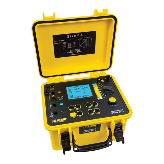
2. PRODUCT FEATURES 2.1 DESCRIPTION The Model 5070 megohmmeter is a top-of-the-line measuring instrument, portable, in a rugged housing with a graphic display. It is capable of operating from internal battery or line power. Automatic detection and measurement of voltage/frequency/input current. -
Page 10: Control Features
Insulation measurement with selectable test voltage (from 40 to 5100 V: 10 V steps from 40 to 1000 V and 100 V steps from 1000 to 5000 V) Insulation measurement with voltage step function (up to 5 steps Megohmmeter Model 5070 1.800.561.8187 information@itm.com www. - Page 11 Activates temperature correction Turns the display backlight ON or OFF Recalls saved data PRINT Printing measurement data is completed through DataView software. Browses through the screens accessible before, during, and after the GRAPH measurement Megohmmeter Model 5070 1.800.561.8187 information@itm.com www. .com...
-
Page 12: Display Features
Indicates the remaining battery charge. Indicates that the generated voltage is dangerous, V > 120 V Indicates that external voltage is present - this symbol is activated when the Start button is pressed if V > 25 V Megohmmeter Model 5070 1.800.561.8187 information@itm.com www. -
Page 13: Special Functions
3. SPECIAL FUNCTIONS This function, located at the top rotary switch position (Blue “SET-UP” position), llows: Megohmmeter Model 5070 1.800.561.8187 information@itm.com www. .com... - Page 14 You may now To exit the alarm setting function, press the DISPLAY button. This will bring you back to the top of the SET-UP menu. Megohmmeter Model 5070 1.800.561.8187 information@itm.com www.
- Page 15 00 to 49 : 01 to 59 selection position. Data from a timed run test can be stored in the Model 5070 at an interval you select. This storage interval can be as fast as once every 10 seconds to as slow as once every 10 minutes.
- Page 16 1.800.561.8187 information@itm.com www. .com...
- Page 17 Sample Time (seconds) = (h+1)*5 where h= total run time in hours. TEMPERATURE UNIT This function toggles the display between Fahrenheit and Celsius scales for temperature display. Range °C or °F Megohmmeter Model 5070 1.800.561.8187 information@itm.com www. .com...
- Page 18 For example, if you set the maximum voltage to 1250 V and place the rotary switch in the 5000 V position and start a test, the Model 5070 will only output 1250 V.
- Page 19 Range 3%, 10%, or 20% BUZZER The Model 5070 is equipped with a buzzer that will emit an audible tone when a key is pressed, at regular intervals during a timed test, or continuously during an Range ON or OFF POWER DOWN 5 minutes of no activity, if a timed test is not in progress.
- Page 20 BAUD RATE This function lets you program in the communication speed between the Model 5070 and your computer. It must be set to 9600 for communication with DataView. desired baud rate. Your choices are 300, 600, 1200, 2400, 4800, 9600, or complete the process.
-
Page 21: Set-Up Menu
Time can be set here. A 24-hour clock is used in the Model 5070. Therefore 3:30pm would be programmed in as 15:30. after you have selected the time set up to complete the process. Turning the rotary switch to SET-UP gives you access to the menu of all blinking cursor is again to the left of the function. -
Page 22: Mode / Print Button
1.800.561.8187 information@itm.com www. .com... - Page 23 GRAPH button, as long as no new measurement has been started. resistance, if it is stored. During the measurement, if the position of the rotary switch is changed, or the START/STOP button is pressed, the measurement is stopped. Megohmmeter Model 5070 1.800.561.8187 information@itm.com www.
- Page 24 SET-UP mode). NOTE: In this mode, the DAR ratio will also be calculated automatically if the times needed to calculate it are less than the second time needed to calculate the PI ratio. Megohmmeter Model 5070 1.800.561.8187 information@itm.com www. .com...
- Page 25 In addition, changes in these ratios over time can be observed and used for preventative maintenance (e.g. to monitor the aging of the insulation of a population of rotating machines). Megohmmeter Model 5070 1.800.561.8187 information@itm.com www.
-
Page 26: Secondary Function - Print
The screens vary depending on the mode selected before the measurement is started. This section, starting on the following page, shows typical screens that can be displayed for each test mode. Megohmmeter Model 5070 1.800.561.8187 information@itm.com www. - Page 27 Voltage bargraph Date and Time DURING the measurement: DISPLAY: Measured resistance Measured resistance DC test voltage DC test voltage Residual current Residual current Measurement duration Measurement duration Insulation resistance bargraph DAR, PI, Capacitance Megohmmeter Model 5070 1.800.561.8187 information@itm.com www. .com...
- Page 28 Measured resistance DC test voltage Leakage current Measurement duration DAR, PI, Capacitance values Test type and test voltage AC/DC input voltage Frequency Leakage current Date, time AC/DC input voltage Frequency Leakage current Voltage bargraph Megohmmeter Model 5070 1.800.561.8187 information@itm.com www. .com...
- Page 29 DURING the measurement: DISPLAY: Measured resistance Measured resistance DC test voltage DC test voltage Leakage current Leakage current Measurement duration Measurement duration DAR, PI, Capacitance Insulation resistance bargraph Residual current (calculation of DD) Megohmmeter Model 5070 1.800.561.8187 information@itm.com www. .com...
- Page 30 Leakage current Residual current (calculation of DD) Date, time Measured resistance DC test voltage AC/DC input voltage Leakage current Frequency Total test time Leakage current DAR, PI, Capacitance Voltage bargraph DD test current Megohmmeter Model 5070 1.800.561.8187 information@itm.com www. .com...
- Page 31 Residual current Date, time DURING the measurement: DISPLAY: Measured resistance Measured resistance DC test voltage DC test voltage Leakage current Leakage current Remaining measurement time Remaining measurement time Insulation resistance bargraph DAR, PI, Capacitance Megohmmeter Model 5070 1.800.561.8187 information@itm.com www. .com...
- Page 32 Leakage current Measurement duration DAR, PI, Capacitance values Test type DC test voltage Programmed duration of the test AC/DC input voltage Frequency Leakage current Date, time AC/DC input voltage Frequency Leakage current Voltage bargraph Megohmmeter Model 5070 1.800.561.8187 information@itm.com www. .com...
- Page 33 DURING the measurement: DISPLAY: Measured resistance Measured resistance DC test voltage DC test voltage Leakage current Leakage current Remaining measurement time Remaining measurement time DAR, PI, Capacitance Insulation resistance bargraph Residual current (calculation of DD) Megohmmeter Model 5070 1.800.561.8187 information@itm.com www. .com...
- Page 34 Leakage current Residual current (calculation of DD) Date, time Measured resistance DC test voltage AC/DC input voltage Leakage current Frequency Total test time Leakage current DAR, PI, Capacitance Voltage bargraph DD test current Megohmmeter Model 5070 1.800.561.8187 information@itm.com www. .com...
- Page 35 Date and Time DURING the measurement: DISPLAY: Measured resistance Measured resistance DC test voltage DC test voltage Leakage current Leakage current Remaining measurement time Remaining measurement time Insulation bargraph DAR, PI, Capacitance in process Megohmmeter Model 5070 1.800.561.8187 information@itm.com www. .com...
- Page 36 Leakage current Voltage bargraph *NOTE: Because the test will stop after the DAR calculation, PI will not be calculated if the time values for this test are longer than those set for DAR. Megohmmeter Model 5070 1.800.561.8187 information@itm.com www. .com...
- Page 37 Date and Time DURING the measurement: DISPLAY: Measured resistance Measured resistance DC test voltage DC test voltage Leakage current Leakage current Remaining measurement time Remaining measurement time Insulation bargraph DAR, PI, Capacitance in process Megohmmeter Model 5070 1.800.561.8187 information@itm.com www. .com...
- Page 38 Leakage current Measurement duration DAR, PI*, Capacitance Test type DC test voltage Programmed duration of the test AC/DC input voltage Frequency Leakage current Date and time AC/DC input voltage Frequency Leakage current Voltage bargraph Megohmmeter Model 5070 1.800.561.8187 information@itm.com www. .com...
-
Page 39: Secondary Function - Graph
If the result of your measurement is outside of the instrument’s range (the display shows the < or > symbol next to the reading), the Temperature Correction function cannot be applied. Temperature correction is not available on Step Voltage tests. Megohmmeter Model 5070 1.800.561.8187 information@itm.com www. - Page 40 The Reference Temperature (Rc Reference Temperature) and the T indicated and used for SET-UP. Note: To store this calculation, press the 2nd + TEMP buttons again (OK is then displayed) before storing everything. Megohmmeter Model 5070 1.800.561.8187 information@itm.com www. .com...
-
Page 41: Secondary Function - Smooth
The SMOOTH function (activated by pressing the 2nd + SMOOTH buttons) function is useful if the insulation values displayed are very unstable. RSMOOTH = RSMOOTH + (R – RSMOOTH) / N Therefore, displayed results are presented more smoothly. Megohmmeter Model 5070 1.800.561.8187 information@itm.com www. -
Page 42: Secondary Function - Alarm
If the Obj is a 3-phase motor, then each test number will represent a e.g. - Test 1 = Phase A to housing Test 2 = Phase B to housing Test 3 = Phase C to housing and so on. Megohmmeter Model 5070 1.800.561.8187 information@itm.com www. .com... - Page 43 MEM mode without saving the results. Total memory space: 128 kB Data management: 8 kB Free memory space: 120 kB An insulation measurement requires 80 bytes. Therefore, approximately 1500 insulation measurements can be stored. Megohmmeter Model 5070 1.800.561.8187 information@itm.com www. .com...
-
Page 44: Second Function - Mr (Recall)
GRAPH if the mode selected before the start of the measurement allows. , press the MR button once again or turn the selector switch to another position. 3.9 CLEARING THE MEMORY Megohmmeter Model 5070 1.800.561.8187 information@itm.com www. .com... - Page 45 Validate by pressing DISPLAY with the CANCEL option highlighted. choose it. appropriate choice is highlighted as described above. Megohmmeter Model 5070 1.800.561.8187 information@itm.com www. .com...
- Page 46 1.800.561.8187 information@itm.com www. .com...
-
Page 47: Maximum Output Voltage
The format of this error code is a 1 or 2 Here are some examples of possible errors: Codes from 0 to 9 identify fatal errors in the hardware. The instrument must be returned to AEMC Instruments for corrective action. ®... -
Page 48: Measurement Functions
(see V Disturbance / V Output on page 25). 4.2 INSULATION MEASUREMENT When the switch is turned to an insulation resistance measurement position, one of following appears: You select an insulation measurement manual mode. Switch Positions: Megohmmeter Model 5070 1.800.561.8187 information@itm.com www. .com... - Page 49 WARNING: Insulation measurements cannot be started if there is an excessively high external voltage on the “+” and “–” terminals. The Model 5070 will automatically inhibit testing. , if the external voltage of the terminals and described next, the insulation test is not started and an audible alarm is Megohmmeter Model 5070 1.800.561.8187...
- Page 50 “+” and “-” terminals of 75 V will cause the Model 5070 to inhibit testing. (Vpeak = (0.03 x 2500 V) = 75 V) Similarly, if during the insulation test, an external voltage greater than the V peak symbol will appear next to the value of the external voltage measured.
-
Page 51: Capacitance Measurement
4.4 RESIDUAL CURRENT MEASUREMENT The residual current circulating in the installation is measured and displayed automatically upon connection to the installation, it is all measured during and after the insulation measurement. Megohmmeter Model 5070 1.800.561.8187 information@itm.com www. .com... -
Page 52: Operation
Press the START/STOP button again to stop the test. The last result remains displayed until the next measurement is made or the switch is turned. When the insulation measurement has stopped, the device under test will be automatically discharged by the Model 5070. Megohmmeter Model 5070 1.800.561.8187 information@itm.com www. -
Page 53: Step Function Mode
A larger deviation or a sudden drop indicates the presence of localized physical damage such as arcing or perforation of the insulation, etc. Procedure: In the SET-UP menu, select “Set Step Function 1, 2 or 3” by scrolling down to Megohmmeter Model 5070 1.800.561.8187 information@itm.com www. - Page 54 (with the highest test voltage) and the initial resistance (with the lowest test voltage). The slope of the curve in ppm/V. The capacitance. Pressing the GRAPH button displays the resistance versus applied test voltage curve. Megohmmeter Model 5070 1.800.561.8187 information@itm.com www. .com...
-
Page 55: Operation Examples
(e.g. dusty, damp cable or transformer insulation). In this case, alligator clips are preferable to hand-held test probes. As soon as the insulation measurement is stopped, the test circuit is automatically discharged using the instrument’s internal discharge feature. Megohmmeter Model 5070 1.800.561.8187 information@itm.com www. - Page 56 BLUE BLACK BLUE JUMPER Braid External insulator Insulator Cable BLUE Guard BLACK BLUE JUMPER Megohmmeter Model 5070 1.800.561.8187 information@itm.com www. .com...
-
Page 57: Dataview ® Software
1.800.561.8187 information@itm.com www. .com... - Page 58 1.800.561.8187 information@itm.com www. .com...
-
Page 59: Megohmmeter Control Panel
For further information about using the Megohmmeter Control Panel, consult the Help system that comes with the product. You can access this Help by clicking the option Help at the top of the Control Panel's screen or by pressing F1 in the program. Megohmmeter Model 5070 1.800.561.8187 information@itm.com www. -
Page 60: Specifications
= 3%, 10%, or 20% NOTE: Vn = Test Voltage >1 mA Load Current: 3 mA approx when starting measurement NOTE: dlSt is the ratio of V Disturbance/V Output and is selectable in SET-UP mode. Megohmmeter Model 5070 1.800.561.8187 information@itm.com www. .com... - Page 61 ±5% of Reading + 3 cts ±15% of Reading + 10 cts Range Resolution 40.0 to 99.9 V 0.1 V 100 to 1500 V 1% of Reading ± 1 ct 1501 to 5100 V Megohmmeter Model 5070 1.800.561.8187 information@itm.com www. .com...
- Page 62 100.0 to 999.9 nA 100 pA 1.000 to 9.999 µA 1 nA 5% of Reading 10.00 to 99.99 µA 10 nA 100.0 to 999.9 µA 100 nA 1000 to 3000 µA 1 µA 10% of Reading Megohmmeter Model 5070 1.800.561.8187 information@itm.com www. .com...
- Page 63 500 V Range 0.01 1000 V Range 1200 1000 0.01 Megohmmeter Model 5070 1.800.561.8187 information@itm.com www. .com...
- Page 64 2500 V Range 3000 2500 2000 1500 1000 0.01 5000 V Range 6000 5000 4000 3000 2000 1000 0.01 Megohmmeter Model 5070 1.800.561.8187 information@itm.com www. .com...
-
Page 65: Power Supply
1.800.561.8187 information@itm.com www. .com... -
Page 66: Mechanical Specifications
0% to 20% Vn 0.1% R / % Vn 0.1% R / % Vn ± 5 cts test voltage *The terms DAR, PI, DD, and the capacity and current leak measurements are included in the Megohmmeter Model 5070 1.800.561.8187 information@itm.com www. .com... -
Page 67: Maintenance
8. MAINTENANCE be replaced by an authorized repair facility recognized by AEMC ® otherwise, AEMC Instruments will not be held responsible for any accident, ® incident, or malfunction following a repair not completed by its service center or an approved repair center. -
Page 68: Storage
8.6 TECHNICAL AND SALES ASSISTANCE If you are experiencing any technical problems, or require any assistance with the proper operation or application of your instrument, please call, mail, fax, or e-mail our technical support team: Megohmmeter Model 5070 1.800.561.8187 information@itm.com www. -
Page 69: Limited Warranty
8.7 LIMITED WARRANTY The Megohmmeter Model 5070 is warrantied to the owner for a period of two years from the date of original purchase against defects in manufacture. This limited warranty is given by AEMC Instruments, not by the distributor from ®... -
Page 70: Appendix A. Utilizing The Guard Terminal
The example of a cable, shown in the diagram below, connecting the guard terminal of the Model 5070 to the surface of the insulation will redirect surface leakage currents away from the true measured value of leakage current from the conductor through the insulation. - Page 71 “i1”. See Figure A-2. Figure A-2 - No Guard Terminal Connected With the guard terminal connected, the surface leakage i1 is removed and has no Figure A-3 - Guard Terminal Connected Megohmmeter Model 5070 1.800.561.8187 information@itm.com www.
-
Page 72: Appendix B. V Disturbance/V Output Feature
If the Model 5070 measures a voltage higher than the V Disturbance/V Output setting allows, no test voltage will be generated when the Start button is pressed. - Page 73 1.800.561.8187 information@itm.com www. .com...
Need help?
Do you have a question about the 5070 and is the answer not in the manual?
Questions and answers