AEMC SIMPLE LOGGER II User Manual
Trms voltage
Hide thumbs
Also See for SIMPLE LOGGER II:
- User manual (52 pages) ,
- Quick start user manual (8 pages) ,
- User manual (48 pages)
Table of Contents
Advertisement
Quick Links
Advertisement
Table of Contents

Subscribe to Our Youtube Channel
Related Manuals for AEMC SIMPLE LOGGER II


Summary of Contents for AEMC SIMPLE LOGGER II
- Page 1 L261 ® SIMPLE LOGGER TRMS VOLTAGE MODEL E N G L I S H User Manual...
- Page 2 Owner’s Record ® The serial number for the Simple Logger II is located on the back of the case. Please record this number and purchase date for your records. ® SIMPLE LOGGER MODEL #: _______________________________________________ SERIAL #: _______________________________________________ PURCHASE DATE: ________________________________________ DISTRIBUTOR: ___________________________________________...
-
Page 3: Table Of Contents
Table of Contents 1. INTRODUCTION ................3 1.1 International Electrical Symbols ..........3 1.2 Definition of Measurement Categories ........4 1.3 Receiving Your Shipment ............4 1.4 Ordering Information ..............4 2. PRODUCT FEATURES ..............5 2.1 Description ................5 2.2 Control Features ...............6 3. SPECIFICATIONS................8 3.1 Electrical ...................8 3.2 Mechanical ................9 3.3 Environmental ................9 3.4 Safety ..................9... - Page 4 APPENDIX A: TROUBLESHOOTING ............21 APPENDIX B: GLOSSARY ..............22 Repair and Calibration ................23 Technical and Sales Assistance ............23 Limited Warranty ...................24 Warranty Repairs ...................24...
-
Page 5: Introduction
CHAPTER 1 INTRODUCTION WARNING These safety warnings are provided to ensure the safety of personnel and proper operation of the instrument. • Read the instruction manual completely and follow all the safety infor- mation before attempting to use or service this instrument. • Never exceed the maximum working voltage ratings given. • NEVER open the back of the instrument while connected to any circuit or input. • Always inspect the instrument accessories and leads prior to use. Replace any defective parts immediately with factory parts. -
Page 6: Definition Of Measurement Categories
1.4.1 Accessories and Replacement Parts Lead-Set of 2, Color-coded 5 ft w/color-coded alligator clips (Rated 600V Cat IV, 15A) ............ Cat. #2140.62 Order Accessories and Replacement Parts Directly Online Check our Storefront at www.aemc.com/store for availability ® Simple Logger II Model L261... -
Page 7: Product Features
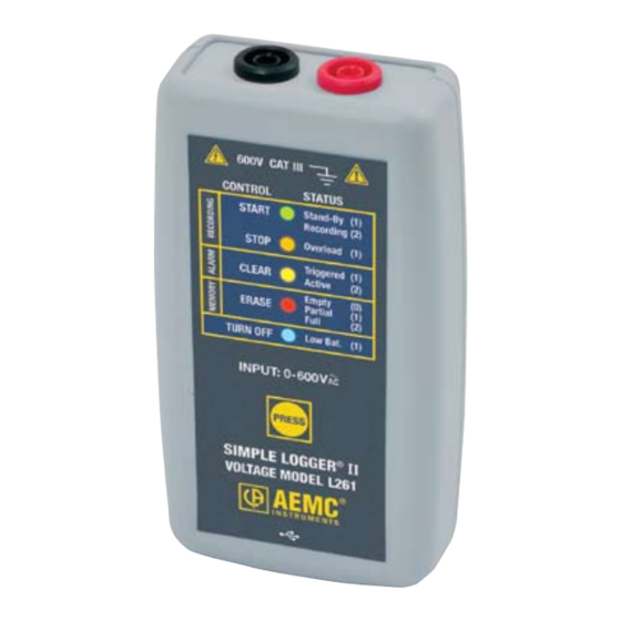
CHAPTER 2 PRODUCT FEATURES Description ® The Simple Logger II Model L261 is a one channel recording device powered by an alkaline battery pack. Line tracking is performed such that 64 samples over one line cycle are taken. Frequency tracking is performed over the range of ±2Hz around the nominal line frequency (50 or 60Hz). Harmonic measurements are calculated from these 64 samples (Harmon- II Control Panel within the ics are only available from the Simple Logger... -
Page 8: Control Features
Control Features Figure 2-2. Key Components and Features 1. 4mm Safety Banana Input Termination - located on the top of the instrument 2. Five LED Indicators The LEDs on the instrument serve two functions: control operation and status function. • The control operation (function when holding down the PRESS button) is indicated with text to the left of each LED. - Page 9 3. Control Button (PRESS) This button marked “PRESS” selects the mode of operation. Use this button to start or stop recordings, erase the memory, clear alarms and turn the instrument ON/OFF. 4. Female Type Mini-B USB Connector - located on the bottom of the instrument 5.
-
Page 10: Specifications
CHAPTER 3 SPECIFICATIONS Electrical Reference Conditions: 23°C ± 3°C, 30-50% RH, DC or 50/60 Hz, battery voltage: 3V ± 10%. MODEL L261 Channels Input Two Recessed Banana Jacks Voltage Range 0 to 600V Resolution 0.1V Accuracy 0 to 5V unspecified (50/60Hz) 5 to 50V: ±(0.5% of Reading + 1V) 50 to 600V: ±(0.5% of Reading + 0.5V) Sample Rate 64 samples/cycle Storage Rate... -
Page 11: Mechanical
Mechanical Dimensions: 4.94 x 2.75 x 1.28” (125 x 70 x 32mm) Weight (with battery): 6.4 oz (181 grams) Case: UL94-V0 Vibration: IEC 68-2-6 (1.5mm 10 to 55Hz) Shock: IEC 68-2-27 (30G) Drop: IEC 68-2-32 (1m) Environmental Operating Temperature: 14° to 122°F (-10° to 50°C) Storage Temperature: -4° to 140°F (-20° to 60°C) Relative Humidity: 0 to 85% @ 95°F (35°C), Non-condensing Altitude: 2000m Safety 600V Cat. III 300V Cat. IV *All specifications are subject to change without notice ®... -
Page 12: Operation
CHAPTER 4 OPERATION LED Control Operation and Status Function The ON/OFF state of the instrument can be determined by pressing the PRESS button for less than 0.5 seconds. If the instrument is ON, the status of the instrument will be shown by the LEDs. If the instrument is OFF no indication will be given (the LEDs will not blink). The instrument is turned ON by pressing the PRESS button until all LEDs light. - Page 13 The status function of each LED is as follows: GREEN STATUS LED OFF Logger is turned OFF or in Low Power Standby state* LED Single-blink Logger is in Standby Mode (and not recording) LED Double-blink Logger is in Record Mode ORANGE STATUS LED OFF...
-
Page 14: 4.2 Connecting The Simple Logger ® Ii To A Computer
® Connecting the Simple Logger II to a Computer ® INSTALL THE DATAVIEW SOFTWARE BEFORE CONNECTING THE SIMPLE ® LOGGER II TO THE COMPUTER. Figure 4-1 shows a typical hook-up. The Simple Logger ® II utilizes an opti- cally isolated USB communication port. Refer to the computer manual to locate the USB port on your computer. Figure 4-1 The logger can be connected to the computer during a recording session, however, additional battery drainage will occur to support the active USB... -
Page 15: Recording Data
The instrument contains protection circuitry to prevent it from being turned on when the battery voltage is below 1.7V. There are two thresholds for the battery voltage: • The first is used to indicate low battery. The low battery indicator will blink when the battery voltage drops below 1.8V. • The second is used to determine when to terminate recording and turn the unit off. -
Page 16: Stopping A Recording Session
4.4.2 Stopping a Recording Session 1. Press and hold the PRESS button. When the STOP (ORANGE) LED lights up, release the button. 2. The GREEN LED will change from a double-blink to a single-blink, indicating STANDBY mode. The data will be retained, even if the instrument is turned OFF. The recorded data is stored in Flash memory, meaning that it will be maintained even in the absence of batteries. The recorded data may be downloaded to a computer. -
Page 17: Data Storage
® Erasing the Memory using DataView 1. Connect the instrument to the computer, then open the Simple Logger ® II Control Panel. 2. Select Erase Memory from the Instrument Menu. 3. A dialog box will appear asking to confirm the erasure of instrument memory. Select Yes to confirm or No to cancel the operation. Data Storage The logger captures trend measurements. The following are a few definitions that will help with the understanding of this section. Input Channel: Source for the measurement channel of the instrument. - Page 18 • The RED LED is OFF, indicating there is no data in memory • PRESS button is used to Start and Stop a Recording Session • If the PRESS button is not pressed for a period of one minute, the instrument will enter a low power STANDBY mode and wait for either another button press or the recording start time to arrive (if a recording is scheduled).
- Page 19 Event: Memory Filled During Recording Session If the logger is recording using the Start/Stop mode and memory is filled before the Recording Session has finished, the session will end. The following happens: • The RED LED double-blinks • The GREEN LED single-blinks At this time: • The memory can be downloaded and cleared • A new recording can be started or scheduled once the memory is cleared Event: Battery Power is Insufficient for a Full Recording Duration If the battery voltage drops below 1.7V, the following will occur: •...
-
Page 20: Reset Button Operation
Event: Recording Session has Ended The logger will be in STANDBY mode if one of the following occurs: • The session terminates due to recording end time being reached when recording in the Start/Stop mode. • The recording in Start/Stop mode fills the memory. • PRESS button The user terminates the session by pressing the until the STOP (ORANGE) LED lights up and releasing the button before the next LED lights, or issues a Stop Recording command II Control Panel. - Page 21 Event: Pressing the RESET Button while Recording (not recommended) • The recording session ends and the GREEN LED changes from a double-blink to a single-blink. • The RED LED double-blinks to indicate that the memory is full. • Some portion of recorded data will be lost. Sample data is buff- ered and assembled into small packets before it is written to Flash.
-
Page 22: Maintenance
CHAPTER 5 MAINTENANCE Use only factory specified replacement parts. AEMC ® will not be held responsible for any accident, incident, or malfunction following a repair done other than by its service center or by an approved repair center. Changing the Batteries WARNING: Turn the unit off before changing the batteries or loss of recorded data may occur. -
Page 23: Appendix A: Troubleshooting
APPENDIX A TROUBLESHOOTING Symptom: After being in a damp, cold environment, the logger does not function. Cause, Correction: Condensation may have formed inside the logger, shorting out the circuitry and discharging the battery. Allow the circuit board to dry thoroughly in a warm location. ®... -
Page 24: Appendix B: Glossary
APPENDIX B GLOSSARY Some general terminology associated with the data collection process is listed here for convenience. Bps: Bits Per Second, a unit of signal transfer speed equal to the ® number of elements per second. The Simple Logger II transfers data at the rate of 115200 bps. -
Page 25: Repair And Calibration
Number (CSA#). This will ensure that when your instrument arrives, it will be tracked and processed promptly. Please write the CSA# on the outside of the shipping container. If the instrument is returned for calibration, we need to know if you want a standard calibration, or a calibration traceable to N.I.S.T. (Includes calibration certificate plus recorded calibration data). Ship To: Chauvin Arnoux , Inc. d.b.a. AEMC ® ® Instruments 15 Faraday Drive Dover, NH 03820 USA Phone: (800) 945-2362 (Ext. 360) -
Page 26: Limited Warranty
Instruments. For full and detailed warranty coverage, please read the Warranty Coverage Information, which is attached to the Warranty Registration Card (if enclosed) or is available at www.aemc.com. Please keep the Warranty Coverage Information with your records. What AEMC ®... - Page 28 05/07 99-MAN 100311 v1 Chauvin Arnoux ® , Inc. d.b.a. AEMC ® Instruments 15 Faraday Drive • Dover, NH 03820 USA • Phone: (603) 749-6434 • Fax: (603) 742-2346 www.aemc.com...
Need help?
Do you have a question about the SIMPLE LOGGER II and is the answer not in the manual?
Questions and answers