Table of Contents
Advertisement
Quick Links
Advertisement
Table of Contents

Related Manuals for AEMC 5070


Summary of Contents for AEMC 5070
- Page 1 5070 MEGOHMMETER E N G L I S H User Manual...
- Page 2 The recommended calibration interval for this instrument is 12 months and begins on the date of receipt by the customer. For recalibration, please use our calibration services. Refer to our repair and calibration section at www.aemc.com. Serial #: ________________________________ Catalog #: 2130.30 Model #:...
-
Page 3: Table Of Contents
3.5 Environmental Specifications .............17 3.6 Mechanical Specifications ..............17 3.7 Safety Specifications ................17 3.8 Variations in Operating Range ............18 4. SPECIAL FUNCTIONS ............... 19 4.1 SET-UP Function ................19 4.1.1 Default Configurations ............19 4.1.2 Instrument Configuration Parameters ........20 4.1.3 SET-UP Menu ...............27 4.2 MODE / PRINT Button ...............28 4.2.1 Primary Function - MODE .............28 4.2.2 Secondary Function - PRINT ..........32 Megohmmeter Model 5070... - Page 4 4.10 Calculation of ΔT from Stored Data ............53 4.11 Maximum Output Voltage ..............54 4.12 List of Error Codes ................54 5. MEASUREMENT FUNCTIONS ............55 5.1 AC/DC Voltage ...................55 5.2 Insulation Measurement ..............55 5.3 Capacitance Measurement ..............58 5.4 Residual Current Measurement ............58 6. OPERATION ..................59 6.1 Performing Measurements ..............59 6.2 Step Function Mode ................60 6.3 Operation Examples................62 Megohmmeter Model 5070...
- Page 5 (Print Result) ....64 6.5 Instantaneous Printing of Measurements (Print Memory) ........67 6.6 Printing Data in Memory 7. DATAVIEW SOFTWARE ..............71 ® 7.1 Installing DataView ................71 ® 7.2 Connecting the Model 5070 to your Computer ........75 7.3 Establishing Communication to the Instrument ........75 7.4 Configuring the Instrument ..............76 7.5 Running the Test ................79 7.6 Exporting the Report to a PDF File ..........82 DataView Megohmmeter Templates ..........83 ® 7.7.1 Megohmmeter Summary Report Template ......83 7.7.2...
-
Page 6: Introduction
• AEMC considers the use of rubber gloves to be an excellent ® safety practice, even if the equipment is properly operated and correctly grounded. • When testing samples with a capacitive component, make sure they have been properly discharged and are safe to touch. Dielectric insulation samples should be short-circuited for at least five times the amount of time they were energized. • Megohmmeters should never be used in an explosive environ- ment. • Only use the leads that are supplied with the megohmmeter. If they are defective or worn, replace before testing. • This instrument can be used on installations rated for 1000V CAT III or 2500V CAT I. Megohmmeter Model 5070... -
Page 7: International Electrical Symbols
CAT IV: For measurements performed at the primary electrical supply (<1000V) such as on primary overcurrent protection devices, ripple control units, or meters. 1.3 Receiving Your Shipment • Match the contents with the ordering information. • Notify your distributor of any missing items. • If the equipment appears to be damaged, file a claim immediately with the carrier and notify your distributor at once. NOTE: Charge the instrument fully before use. Megohmmeter Model 5070... -
Page 8: Ordering Information
1.4 Ordering Information Megohmmeter Model 5070.............Cat. #2130.30 Includes extra large tool bag, set of three 10 ft (5kV) leads (red/black/blue) with integral hippo clips (5000V), one guard terminal jumper lead, RS-232 DB9 F/F 6 ft null modem cable, RS-232 to USB adapter, US 115V power cord, rechargeable battery pack, and a USB stick with DataView software and user manual. -
Page 9: Product Features
The operation is controlled by a microprocessor for data acquisition, pro- cessing, and display of measurements and the storage and printing of results. Advantages: • Digital filtering of insulation measurements • Automatic voltage measurement • Automatic detection of external AC or DC voltages on the terminals, before or during insulation measurements, disabling or stopping the mea- surements when measurement accuracy is no longer guaranteed • Threshold programming to trigger audible alarms • Timer for measurement time checks • Fuse protection of the instrument with detection and display of defective fuses • Operator safety by automatic discharge of residual high voltage on the equipment tested Megohmmeter Model 5070... -
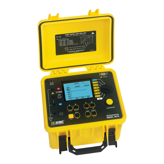
Page 10: Control Features
• Automatic shutdown of the instrument to save battery power • Battery charge indication • Large backlit graphic display that is very easy to read • Memory (128KB), real time clock, and serial interface • Control and programming of the instrument from a PC (using DataView software) ® • Direct printing with a serial printer (optional accessory - Cat. #2140.21) 2.1 Control Features 1. Safety terminals: “+”, “G” and “-” 2. Protective fuse access 3. AC power plug (direct operation on AC and battery recharge) 4. Back-lit liquid crystal display 5. RS-232 serial interface male plug (9-pin) • For connection to a PC or printer 6. Rotary selector switch with 8 positions: • OFF - Instrument is off Megohmmeter Model 5070... - Page 11 TEMP - activates temperature correction of the measurement to the reference temperature programmed in SET-UP. • - Selects a parameter to be modified to the right. - Turns the display backlight ON or OFF. • MEM - Saves measured values. MR - Recalls saved data. • MODE - Before starting a test, the mode function allows selection of run time, sample rate, DAR PI and ratio times. PRINT - direct printing of test result(s) on a serial or parallel printer. • DISPLAY - Browses through the various screens accessible before, during and after the measurement. • GRAPH - After a “timed run”, the Graph mode displays insulation resis- tance versus time in a graph format. Megohmmeter Model 5070...
-
Page 12: Display Features
2.2 Display Features REMOTE Indicates that the instrument is controlled remotely via the RS-232 interface. In this mode, all of the keys and the rotary switch are inac- tive, except for the OFF position. COM Flashes when data is transmitted to the serial interface. On continu- ously if there is a problem in transmission. Indicates that the secondary function of a key will be used. Indicates that the “programmed time test” mode was selected before the measurement was started. DAR Indicates that the “automatic calculation of Dielectric Absorption Ratio” mode was selected before the measurement was started. Indicates that the “automatic calculation of Polarization Index” mode was selected before the measurement was started. Indicates that the “automatic calculation of “Dielectric Discharge Index” mode was selected before the measurement was started. SMOOTH Smooths the insulation measurement readings on the display for better visibility. ALARM Indicates that the alarm is activated. An audible alarm will sound if the value measured is above the limit defined in the SET-UP mode. Indicates the battery charge condition. Voltage generated dangerous, V > 120V External voltage present - this symbol is activated when the Start button is pressed if V > 25V RMS. Megohmmeter Model 5070... -
Page 13: Specifications
Measurement Category: 1000V CAT III or 2500V CAT I (transients ≤2.5kV) 3.3 Insulation Resistance Method: Voltage-current method according to EN 61557-2 (ed. 02/97) Nominal Output Voltage: 500, 1000, 2500, 5000 V (or selectable from 40V to 5100V) Adjustments Available in Variable Mode: 10V from 40V to 1000V 100V from 1000V to 5100V Open-circuit Voltage: ≤1.1 x Vn ±2V (Vn ±2% in variable mode) Max. Overload of Voltage Vn: (1.05 + dISt) Vn + 50V with dlSt = 3%, 10% or 20% NOTE: Vn = Test Voltage Megohmmeter Model 5070... -
Page 14: Measurement Ranges
5000V 400MΩ to 4.00 to 40.0 to 400GΩ to 4.00 to Range 2.000 to 3.999TΩ 3.999GΩ 39.99GΩ 399.9GΩ 1.999TΩ 10.00TΩ Resolution 1MΩ 10MΩ 100MΩ 1GΩ 10GΩ Accuracy ±5% of Reading + 3cts ±15% of Reading + 10cts Megohmmeter Model 5070... - Page 15 5MΩ 5000V 100GΩ 120s Typical discharge time for a capacitive component to reach 25V Initial Voltage 500V 1000V 2500V 5000V Discharge time (C in µF) C x 3s C x 4s C x 4s C x 7s Megohmmeter Model 5070...
- Page 16 Typical changes in test voltages as a function of the load: 500V Range 0.01 Resistance (MΩ) 1000V Range 1200 1000 0.01 Resistance (MΩ) Megohmmeter Model 5070...
- Page 17 2500V Range 3000 2500 2000 1500 1000 Resistance (MΩ) 5000V Range 6000 5000 4000 3000 2000 1000 Resistance (MΩ) Megohmmeter Model 5070...
-
Page 18: Power Supply
Number of Measurements 5s on nominal charge Test Voltage Nominal Charge (with 25s pause between each measurement) 500V 500kΩ 6500 1000V 1MΩ 5500 2500V 2.5MΩ 4000 5000V 5MΩ 1500 Average Battery Life: The operating time will be 15 days or 3 weeks, based upon a 10 minute long PI measurement. Recharge Time: 6 hours for 100% capacity (10 hours if the battery is completely drained) 0.5 hours for 10% capacity (charge life: 2 days approximately) Megohmmeter Model 5070... -
Page 19: Environmental Specifications
3.5 Environmental Specifications Operating Range: 14° to 104°F (-10° to 40°C) during recharging of batteries 14° to 131°F (-10° to 55°C) during measurement 10 to 80% RH Storage: -40° to 158°F (-40° to 70°C); 10 to 90% RH Altitude: <2000m 3.6 Mechanical Specifications Case Dimensions (LxWxH): 10.63 x 9.84 x 7.09" (270 x 250 x 180mm) Weight: 9.5 lbs (4.3kg) approx 3.7 Safety Specifications Electrical safety according to EN 61010-1 (Ed. 2 for 2001), EN 61557 (ed. 97) Double insulation: 1000V CAT III 2500V CAT I Pollution Degree 2 Electromagnetic Compatibility: NF EN 61326-1 (Ed. 97) + A1, industrial environment category Mechanical Protection: IP 53 per NF EN 60529 (Ed. 92) IK 04 per NF EN 50102 (Ed. 95) Megohmmeter Model 5070... -
Page 20: Variations In Operating Range
0% to 20% Vn MΩ 0.1% R / % Vn 0.1% R / % Vn ± 5cts test voltage *The terms DAR, PI, DD and the capacity and current leak measurements are included in the quantity “MΩ”. Megohmmeter Model 5070... -
Page 21: Special Functions
∆T for R/2 Calculate ∆T from Memory 5100V Maximum Output Voltage Set Default Parameter Clear Memory V Disturbance / V Output Buzzer Power Down 9600 / RS232 Baud Rate Europe Units 04.02.2004 Date (d.m.y) 15:47 Time (h:m) Megohmmeter Model 5070... -
Page 22: Instrument Configuration Parameters
To adjust the alarm settings, press the ▼ button until the blinking cursor is to the left of alarm settings. To adjust the alarm value press the ► button. From the screen displayed, you can adjust low limit resistance values for 500V, 1000V, 2500V, 5000V or the three adjustable voltage positions. To change the low limit for any of these voltage positions, use the ▲ and ▼ but- tons to select the voltage, then press the ► button to highlight the resistance value for that voltage. Next, use the ▲ and ▼ buttons to increase or decrease the value at the blinking cursor position. Once the desired resistance value has been programmed, press the ◄ button to move the cursor again to the voltage selection part of the screen. You may now select the different voltage and adjust its value as just described. To exit the alarm setting function, press the DISPLAY button. This will bring you back to the top of the SET-UP menu. Megohmmeter Model 5070... - Page 23 When the desired voltage is on screen, press the ◄ button to move the cursor back to the parameter selection position. TIMED RUN (h : m) This function lets you set a time from 1 minute to 49 hours and 59 minutes to run an insulation resistance test. The Model 5070 will automatically end the test at the end of the timed run. Range 00 to 49 : 01 to 59 To change the length of time that a test will run, press the ► button to move the blinking cursor to the hour in TIMED-RUN. Use the ▲ and ▼ buttons to increment or decrement the hours. Next, press the ► to select the minute value. Use the ▲ and ▼ buttons to increment or decrement the minutes. When finished, press the ◄ button to move the cursor back to the parameter selection position. Megohmmeter Model 5070...
- Page 24 SAMPLE TIME (m : s) Data from a timed run test can be stored in the Model 5070 at an interval you select. This storage interval can be as fast as once every 5 seconds to as slow as once every 10 minutes. Range 00 to 59 : 05 to 59 DAR (s : s) The Dielectric Absorption Ratio is a ratio of insulation resistance measured at two predetermined times. The reading at the first time mark is then divided into the reading at the second time mark to calculate the ratio. The typical times used for...
- Page 25 *The minimum sample time is related to the total duration of the test (Total Run Time). It is equal to : Sample Time (seconds) = (h+1)*5 where h= total run time in hours. TEMPERATURE UNIT This function toggles the display between Fahrenheit and Celsius scales for tem- perature display. Range °C or °F Megohmmeter Model 5070...
- Page 26 Some materials have a different rate of change. This feature lets you program the temperature change (ΔT) at which the resistance halves for the equipment you will be testing. This value will be used when correcting results to a reference temperature. Range -15°C to +75°C CALCULATE ΔT FROM MEMORY The Model 5070 has the ability to calculate ΔT from three previously stored testsre- sults at different temperatures from one material in the event that no ΔT is selected for the present test. MAXIMUM OUTPUT VOLTAGE The Model 5070 provides the ability to limit the maximum test voltage to a value you specify from 40 to 5100 volts. When programmed, the instrument will not gen- erate a higher voltage to conduct the test even if the switch position indicates a higher voltage. For example, if you set the maximum voltage to 1250 volts and you place the rotary switch in the 5000 volt position and start a test, the Model 5070 will only output 1250 volts. Range 40 to 5100V Megohmmeter Model 5070...
- Page 27 10%, the presence of 100 volts (1000V * 10% = 100) before the test starts will inhibit the test. Range 3%, 10% or 20% BUZZER The Model 5070 is equipped with a buzzer that will emit an audible tone when a key is pressed, at regular intervals during a timed test, or will be on continuously during an alarm trip. This function lets you toggle the buzzer on or off. Range ON or OFF POWER DOWN The Model 5070 has a power save feature which turns the unit’s display off after 5 minutes of no activity, if a timed test is not in progress. This function lets you toggle this feature on or off. Range ON or OFF Megohmmeter Model 5070...
- Page 28 To adjust the baud rate, press the right arrow ► button to highlight the current setting. Next, press the up ▲ or down ▼ arrow buttons to select the desired baud rate. Your choices are 300, 600, 1200, 2400, 4800, 9600 or parallel. Press the right arrow ► button after you have selected the baud rate to complete the process. Range 300 to 9600 / RS-232 or – / Parallel UNITS The Model 5070 can display the date in either US (m.d.y) or European (d.m.y) fashion. This choice can be toggled here. Press the down arrow ▼ button until the blinking cursor is to the left of Units. To select the desired format, press the right arrow ► button to highlight the current setting. Next, press the up ▲ or down ▼ arrow buttons to select either USA or Europe. Press the right arrow ► button after you have selected the desired units to complete the process.
-
Page 29: Set-Up Menu
• Line two indicates the Model 5070’s Instrument Number and Software Version. • The selection cursor will be blinking and positioned to the left of the “Display Contrast” parameter. To adjust the “Display Contrast” parameter, press the ► button to move the blink- ing cursor to display contrast value. The default value is 80. Use the ▲ and ▼ buttons to lighten or darken the display. The higher the number the lighter the display will be. When finished, press the ◄ button to move the cursor back to the parameter selection position. The arrow buttons can be used to modify any parameter. Megohmmeter Model 5070... -
Page 30: Mode / Print Button
Duration Sample surement samples. The measurement (h:m) (m:s) is started by pressing the START/STOP Timed Run 02:30 01:40 button and stops automatically after Timed Run + DD the time programmed by the user has DAR (s/s) 30/60 occurred. PI (m/m) 1/10 Megohmmeter Model 5070... - Page 31 The samples and the curve are automatically stored with the final value of the resistance, if it is stored. During the measurement, if the position of the rotary switch is changed, or the START/STOP button is pressed, the measurement is stopped. Megohmmeter Model 5070...
- Page 32 Timed Run + DD NOTE: In this mode, the DAR ratio will DAR (s/s) 30/60 also be calculated automatically if the (m/m) 1.0/10 times needed to calculate it are less than the second time needed to calculate the PI ratio. Megohmmeter Model 5070...
- Page 33 What are the DAR (Dielectric Absorption Ratio) and the PI (Polarization Indexes)? It is beneficial to calculate insulation quality ratios, in addition to the quantitative insulation resistance value, because they can be used to eliminate the influence of certain parameters likely to invalidate the “absolute” insulation measurement. The most important of these parameters are: • Temperature and relative humidity with which insulation resistance varies to a quasi-exponential law. • The leakage currents (capacitive charging current, dielectric absorption cur- rent) are created by the application of the test voltage. Even though they gradually fall off, they affect the measurement at the start for a length of time that depends on whether the insulation is in good condition or degraded. These ratios complete the “absolute” insulation value, and reliably reflect whether the insulation layers are in good or poor condition. Megohmmeter Model 5070...
-
Page 34: Secondary Function - Print
There are two or three choices in the print mode depending on when it is accessed: • If you access the print mode right after the completion of a test, you will see “Print result” as the first choice. • If you access the print mode without running a test, “Print memory” will be your first choice. PRINT Print result: Print result Immediate printing of a measurement following a measurement or after access Print memory to the MR (Memory Recall) mode. Baud rate / Port 9600 / RS232 Print memory: Printing of stored data. Baud rate / Port: Display of baud rate selected in the SET-UP menu. Megohmmeter Model 5070... -
Page 35: Display / Graph Button
4.3 DISPLAY / GRAPH Button 4.3.1 Primary Function - DISPLAY The primary function of this button is used to browse through the various screens of information available before, during or after the measurement. The screens vary depending on the mode selected before the measurement is started. This section, starting on the following page, shows typical screens that can be displayed for each test mode. Megohmmeter Model 5070... - Page 36 10 100 1 10 100 1 10 100 1 10 Information Displayed: Information after pressing DISPLAY: Measured resistance Measured resistance DC test voltage DC test voltage Residual current Residual current Measurement duration Measurement duration Insulation resistance bargraph DAR, PI, Capacitance Megohmmeter Model 5070...
- Page 37 AC/DC input voltage Frequency Input voltage 0.1V AC Leakage current Frequency 0.0Hz Date, time Input current 24.6pA Date: 09.28.2003 Time: 22:49 After 2nd Press on Display: 0.1 V 0.0Hz 24.6pA AC/DC input voltage Frequency Leakage current Voltage bargraph 1000 Megohmmeter Model 5070...
- Page 38 DD current Information Displayed: Information after pressing DISPLAY: Measured resistance Measured resistance DC test voltage DC test voltage Leakage current Leakage current Measurement duration Measurement duration DAR, PI, Capacitance Insulation resistance bargraph Residual current (calculation of DD) Megohmmeter Model 5070...
- Page 39 DD current 24. 6 pA 2.55 After 1 Minute: After 2nd Press on Display: Measured resistance DC test voltage AC/DC input voltage Leakage current Frequency Total test time Leakage current DAR, PI, Capacitance Voltage bargraph DD test current Megohmmeter Model 5070...
- Page 40 10 100 1 10 100 1 10 100 1 10 Information Displayed: Information after pressing DISPLAY: Measured resistance Measured resistance DC test voltage DC test voltage Leakage current Leakage current Remaining measurement time Remaining measurement time Insulation resistance bargraph DAR, PI, Capacitance Megohmmeter Model 5070...
- Page 41 Input voltage 0.1V AC Frequency Frequency 0.0 Hz Leakage current Input current 20.6pA Date, time Date: 10.18.2003 Time: 09:49 After 2nd Press on Display: 0.1 V 0.0Hz 20.6pA AC/DC input voltage Frequency Leakage current Voltage bargraph 1000 Megohmmeter Model 5070...
- Page 42 Information Displayed: Information after pressing DISPLAY: Measured resistance Measured resistance DC test voltage DC test voltage Leakage current Leakage current Remaining measurement time Remaining measurement time DAR, PI, Capacitance Insulation resistance bargraph Residual current (calculation of DD) Megohmmeter Model 5070...
- Page 43 DD current 11.5 5 pA 2.55 After 1 Minute: After 2nd Press on Display: Measured resistance DC test voltage AC/DC input voltage Leakage current Frequency Total test time Leakage current DAR, PI, Capacitance Voltage bargraph DD test current Megohmmeter Model 5070...
- Page 44 10 100 1 10 100 1 10 100 1 10 Information Displayed: Information after pressing DISPLAY: Measured resistance Measured resistance DC test voltage DC test voltage Leakage current Leakage current Remaining measurement time Remaining measurement time Insulation bargraph DAR, PI, Capacitance in process Megohmmeter Model 5070...
- Page 45 AC/DC input voltage Frequency Leakage current Voltage bargraph 1000 *NOTE: Because the test will stop after the DAR calculation, PI will not be calculated if the time values for this test are longer than those set for DAR. Megohmmeter Model 5070...
- Page 46 10 100 1 10 100 1 10 100 1 10 Information Displayed: Information after pressing DISPLAY: Measured resistance Measured resistance DC test voltage DC test voltage Leakage current Leakage current Remaining measurement time Remaining measurement time Insulation bargraph DAR, PI, Capacitance in process Megohmmeter Model 5070...
- Page 47 Input voltage 0.1V DC Frequency Frequency 0.0 Hz Leakage current Input current 20.6pA Date and time Date: 10.18.2003 Time: 10:03 After 2nd Press on Display: 0.1 V 0.0Hz 20.6pA AC/DC input voltage Frequency Leakage current Voltage bargraph 1000 Megohmmeter Model 5070...
-
Page 48: Secondary Function - Graph
At the completion of a test, press the 2nd + TEMP buttons. This brings up the Temperature Correction display. This function provides the ability to display and store temperature corrected Insula- tion Resistance readings. Therefore, tests compared to historical data can all be referenced to a common temperature for better qualitative analysis. NOTE: • The TEMP function can be activated only after a measurement has been completed either before or after it is stored. • If the result of your measurement is outside of the instrument’s range (the display shows the < or > symbol next to the reading), the Tempera- ture Correction function cannot be applied. • Temperature correction is not available on Step Voltage tests. Megohmmeter Model 5070... - Page 49 Rc at 28.5°C 328.5MΩ • The calculation is performed imme- diately and the result is displayed as Rc along with the Reference Temperature. • This indicates what the measurement result would have been at the refer- ence temperature. • The Reference Temperature (Rc Reference Temperature) and the coef- ficient ΔT indicated and used for the calculation are those defined in SET- Note: To store this calculation, press the 2nd + TEMP buttons again (OK is then displayed) before storing everything. NOTE: • During the procedure, pressing the DISPLAY button or turning the rotary switch cancels the calculation in progress. • If the coefficient ΔT used for the calculation is not known, the instrument can calculate it in advance using at least 3 stored measurements made at different temperatures (see § 4.10). Megohmmeter Model 5070...
-
Page 50: Down / Smooth Button
Insulation Resistance Value is 991 megohms. All the historical data is at 104°F. The corrected Insulation Resistance value corrected to 104°F for this motor is calculated by the Model 5070 to be 284.4 megohms using the formula above when temperature correction is activated. -
Page 51: Up / Alarm Button
Increases the value of the flashing parameter displayed or selects the next param- eter up. 4.6.2 Secondary Function - ALARM To activate the ALARM function before or during a test, press the 2nd + ALARM buttons. The word ALARM will appear at the top right side of the display. If the insulation resistance drops below the set value at any time during the test, the ALARM symbol will flash and the buzzer will be continuously on (if activated), as long as the alarm condition exists. The alarm function can be deactivated at any time by pressing the 2nd + ALARM buttons again. 4.7 ► / Button 4.7.1 Primary Function - ► Selects the parameter to be modified to the right or moves the cursor on a graph screen to the right. 4.7.2 Secondary Function - To activate the display backlight, press the 2nd + buttons. To deactivate, press the 2nd + buttons again. Megohmmeter Model 5070... -
Page 52: Mem / Mr Button
! • To cancel, press the ▼ button to highlight CANCEL, then press the ► O.K. button to confirm. CANCEL When the MEM key is pressed again, the measurement results are recorded at the selected memory address (whether occupied or not). All information from the measurement will be stored at a single location in memory: date, time, test mode and voltage, insulation resistance, capacitance, residual cur- Megohmmeter Model 5070... -
Page 53: Second Function - Mr (Recall)
02 03 11.24.2003 15:04 2150V • To access more data, press DISPLAY 02 02 10.29.2003 21:45 975V repeatedly, or GRAPH, if the mode 02 01 09.30.2003 02:43 5000V selected before the start of the 01 02 09.02.2003 15:07 measurement allows. To exit the MR function, press the MR button once again or turn the selector switch to another position. Megohmmeter Model 5070... -
Page 54: Clearing The Memory
02 03 24.11.2003 15:04 2150V CANCEL To erase the entire memory: • Select “Clear All” by pressing the ▼ button to highlight it and the ► button to choose it. • The operation is confirmed or cancelled by pressing the ► button when the appropriate choice is highlighted as described above. SET-UP SET-UP Clear memory: !WARNING! Select Data Sets to Clear All data sets Clear All will be cleared! O.K. CANCEL Megohmmeter Model 5070... -
Page 55: Calculation Of Δt From Stored Data
5078V 30°C Clear Memory 13 58 178.5MΩ 5078V 37°C V Disturbance / V Output 02 03 328.5MΩ 5078V 23°C Buzzer 02 02 328.5MΩ 5078V 23°C Power Down 02 01 328.5MΩ 5078V 23°C Baud Rate 9600 / RS232 Megohmmeter Model 5070... -
Page 56: Maximum Output Voltage
Here are some examples of possible errors: Codes from 0 to 9 identify fatal errors in the hardware. The instrument must be returned to AEMC Instruments for corrective action. ® Codes from 20 to 25 identify semi-fatal errors, except for codes 21 and 25. -
Page 57: Measurement Functions
You select an insulation measurement 2500 V with a fixed/standard test voltage, in manual mode. Switch Positions: Input voltage 230V AC 500V - 2TΩ Frequency 50.0 Hz 1000V - 4TΩ Input current 24.6nA 2500V - 10TΩ Date: 09.28.2003 Time: 22:39 5000V - 10TΩ Megohmmeter Model 5070... - Page 58 If the beeper is selected as “ON” in the SET-UP mode, an audible beep is emit- ted every 10 seconds to indicate that a test is in process. A number of special functions can be performed during the test. Chapter 4 describes these functions. WARNING: Insulation measurements cannot be started if there is an excessively high external voltage on the “+” and “–” terminals. The Model 5070 will automatically inhibit testing. Megohmmeter Model 5070...
- Page 59 Example A: The test is to be conducted at 2500V, dISt is set to 3%. Therefore, before the test starts, a voltage present at the “+” and “-” terminals of 75V will cause the Model 5070 to inhibit testing. (Vpeak = (0.03 x 2500V) = 75V) Similarly, if during the insulation test, an external voltage greater than the V peak (as defined below) is detected, the measurement is stopped and the symbol appears next to the value of the external voltage measured.
-
Page 60: Capacitance Measurement
Similarly, if the DAR or PI mode is selected as measurement mode before the test, the measurement is stopped automatically after the time programmed to calculate them has occurred (time defined in SET-UP). A number of special functions can be used during the measurement (see § 4). 5.3 Capacitance Measurement The capacitance measurement is performed automatically during the insulation measurement, and is displayed after the measurement stops and the circuit has been discharged. 5.4 Residual Current Measurement The residual current circulating in the installation is measured and displayed auto- matically upon connection to the installation, it is all measured during and after the insulation measurement. Megohmmeter Model 5070... -
Page 61: Operation
Date: 09.28.2003 Time: 22:39 Connect the Red (+) and the Black (-) cables to the test object. Connect the Blue Guard jumper and cable, if required for the test (see Appendix A “When to use the Guard Terminal”). Next, (unless the step function mode is selected) select the measurement mode to be used (Manual Stop, Manual Stop +DD, Timed Run, Timed Run +DD, DAR or PI) by pressing the MODE button (see § 4.2.1) • Press the START/STOP button to begin the measurement test. If the voltage present is greater than the maximum allowed value, the measurement will be prohibited. The DISPLAY button can be used to scroll through the information available during the test. This information depends on the measurement mode selected (see § 4.2.1). If the insulation values displayed are very unstable, a digital filter can be activated by pressing SMOOTH to smooth them (see § 4.5.2). Megohmmeter Model 5070... -
Page 62: Step Function Mode
This function is based upon the principle that ideal insulation produces the same resistance no matter what the test voltage applied. Any negative variation of this resistance means that the insulation may be defective. The resistance of defective insulation will decrease as the test voltage increases. This phenomenon is rarely observed with “low” test voltages, therefore at least 2500V must be applied. The usual test condition is a voltage increasing in 5 steps, each lasting for 1 minute minimum. Assessment of the result: • A deviation of the resistance = f(test voltage) curve that exceeds 500ppm/V generally indicates the presence of mold or other deterioration. • A larger deviation or a sudden drop indicates the presence of localized physical damage such as arcing or perforation of the insulation, etc. Megohmmeter Model 5070... - Page 63 • Then, start the measurement by pressing the START/STOP button. During the measurement, the following screens can be accessed by pressing the DISPLAY button: 234.5M 234.5M 4078V 24.6pA 4078V 24.6pA Remaining time 00:01:43 Remaining time 00:01:43 MΩ ∆R 3000V ∆V kΩ MΩ GΩ TΩ ∆R/(R*∆V) (ppm/V) 10 100 1 10 100 1 10 100 1 10 Capacitance Megohmmeter Model 5070...
-
Page 64: Operation Examples
3000 5000 through the various samples recorded and 2500 4000 for each see: 2000 3000 • The insulation resistance value 1500 2000 1000 1000 • The applied test voltage 1:00 2:00 3:00 4:00 5:00 • The time of measurement 6.3 Operation Examples Connection diagram for measurement of low resistance insulation (e.g. motor) BLACK Megohmmeter Model 5070... -
Page 65: Megohmmeter Model
When measuring high levels of insulation (>1GΩ), it is advisable to use the “G” guard terminal to eliminate the influence of surface leakage currents. The guard is connected between the two measurement contact points, and the surface suscep- tible to surface currents, (e.g. dusty, damp cable or transformer insulation). In this case, alligator clips are preferable to hand-held test probes. As soon as the insulation measurement is stopped, the test circuit is automatically discharged using the instrument’s internal discharge feature. Connection diagram for measurement of high resistance insulation a) Example of a motor (reduction of capacitive effects) BLUE BLACK BLUE JUMPER b) Example of a cable (reduction of superficial leak effects) Braid External insulator Insulator Cable BLUE Guard BLACK BLUE JUMPER Megohmmeter Model 5070... -
Page 66: Printing Measured Values (Mode / Print Button)
If the transmission of data to the printer is successful, the COM symbol flashes at the top left of the display unit. • If a problem occurs, the COM symbol remains lit steadily at the top left of the display unit. 6.5 Instantaneous Printing of Measurements (Print Result) When this print mode is selected, the following are printed, in order: • General information concerning the measurement • The measurement result • If the TEMP function was activated, the measurement result referred to the reference temperature • For a Timed Run test, the list of recorded samples To stop printing, move the position of the selector switch to any other position. Megohmmeter Model 5070... - Page 67 Depending on the function used, the following formats are obtained: Any measurement except step function measurements AEMC Instruments Model 5070 Instrument number: 000 001 Company:......Address:.............. Tel.:....Fax:....Email:....Description:....... OBJECT: TEST: (printed only in MR mode) INSULATION RESISTANCE TEST Date 01.31.2003 Starting time: 14h55 Running time: 00:15:30 Temperature: 23°C...
- Page 68 Date of next test: ../../..Remarks:.............. Operator: ......Signature: ......Step function measurement AEMC Instruments Model 5070 Instrument number: 000 001 Company:......Address:.............. Tel.:....Fax:....Email:....Description:....... OBJECT: TEST: (printed only in MR mode) STEP FUNCTION TEST Date 01.31.2003 Starting time:...
-
Page 69: Printing Data In Memory (Print Memory)
13 : 58 02 02 10.29.2003 21:45 975V 02 : 03 02 01 09.30.2003 02:43 5000V 02 : 02 01 02 09.02.2003 15:07 Once they have been selected, do one of the following: • To start printing, press the PRINT key again. • To exit without printing, change the rotary switch position. • To stop printing, change the rotary switch position. The printing of each group of data is reduced to the main results. Megohmmeter Model 5070... - Page 70 Depending on the measurement performed, the following formats are obtained. Any measurement except step function measurements AEMC Instruments Model 5070 Instrument number: 000 001 Company:......Address:.............. Tel.:....Fax:....Email:....Description:....... OBJECT: TEST: INSULATION RESISTANCE TEST Date 01.31.2003 Starting time: 14h55 Running time: 00:15:30 Temperature: 23°C Relative humidity: ..%...
- Page 71 PI (10’/1’) 2.345 -.—- Capacitance 110 nF …etc.…………………………………… Date of next test: ../../..Remarks:............Operator:....... Signature: ......Step function measurement AEMC Instruments Model 5070 Instrument number: 000 001 Company:......Address:.............. Tel.:....Fax:....Email:....Description:....... Megohmmeter Model 5070...
- Page 72 2.182 GOhm 0:10 5000 V 3237 V 2.023 GOhm 604 GOhm ΔR 4000 V ΔV ΔR/(R*ΔV) (ppm/V) -57 ppm Capacitance 110 nF OBJECT: TEST: …etc.…………………………………… Date of next test: ../../..Remarks:.............. Operator:......Signature: ......Megohmmeter Model 5070...
-
Page 73: Dataview ® Software
BEFORE CONNECTING THE INSTRUMENT TO THE COMPUTER. NOTE: When installing, the user must have Administrative access rights during the installation. The users access rights can be changed after the installation is complete. DataView must be reinstalled for each user in a multi-user system. ® USB Flash Drive Install 1. Insert the USB stick into an available USB port (wait for driver to be installed). 2. If Autorun is enabled then an AutoPlay window should appear as shown. Megohmmeter Model 5070... - Page 74 • *Adobe Reader - Links to the Adobe website to download the most recent ® version of Adobe Reader to the computer. Adobe Reader is required for ® ® viewing PDF documents supplied with DataView ® • *DataView Updates - Links to the online DataView software updates to ® check for new software version releases. • *Firmware Upgrades - Links to the online firmware updates to check for new firmware version releases. Megohmmeter Model 5070...
- Page 75 NOTE: The PDF-XChange option must be selected to be able to generate PDF reports from within DataView ® Figure 7-2 12. In the Ready to Install the Program window, click on Install. 13. If the instrument selected for installation requires the use of a USB port, a warning box will appear, similar to Figure 7-3. Click OK. Megohmmeter Model 5070...
- Page 76 NOTE: If you connected your instrument to the computer before installing the software and drivers, you may need to use the Add/Remove Hard- ware utility to remove the instrument driver before repeating the process. Megohmmeter Model 5070...
-
Page 77: Connecting The Model 5070 To Your Computer
7.2 Connecting the Model 5070 to your Computer The Model 5070 is supplied with a serial interface cable necessary for connecting the instrument to the computer. This cable (Cat. #2119.45) is equipped with a 9-pin connector on each end (see diagram in Appendix B). To connect the megohmmeter to your computer: • Connect the 9-pin connector from one end of the cable to the serial port on the front panel of the Model 5070 megohmmeter. • Connect the 9-pin connector from the other end of the cable to an avail- able serial port on the back of your computer. 7.3 Establishing Communication to the Instrument Double-click the Megohmmeter Icon in the DataView folder that was created • during software installation. • The Connection dialog box will appear. Make sure that the communication port matches the port that the serial cable is plugged into. Figure 7-4 • The communication rate (baud rate) will default to 9600 and should be acceptable to any computer. This is also the default rate for the Model 5070. You... -
Page 78: Configuring The Instrument
7.4 Configuring the Instrument Click the Configure button in the Control Panel. The following settings appear. General Settings - for programming the 5070’s main functions. Figure 7-5 Variable Voltages - for programming the three selectable voltages and their alarm set points. Figure 7-6 Megohmmeter Model 5070... - Page 79 Ramp Voltages - for programming the three ramp profiles. Figure 7-7 Temperature - for programming the temperature correction variable. Figure 7-8 These settings configure every aspect of the megohmmeter. Each field is identical to the programmable features available from the instrument front panel itself. Refer to Chapter 4 for a complete description of each configurable function. Megohmmeter Model 5070...
- Page 80 • Clear Memory: Erases all contents in all memory locations in the megohmmeter. • Download: Retrieves the stored data from all memory locations within the megohmmeter for naming and storing on the computer’s disk drive memory. Once all fields in each of the 4 tabs of the Setup dialog box have been configured, it is recommended that you perform the following steps. 1. Click on the Save to Disk button. 2. Name and save the file. 3. Click on the Write to Inst button to configure the megohmmeter with this new configuration. Click on the Close button to exit Setup and return to the Control Panel. Megohmmeter Model 5070...
-
Page 81: Running The Test
• Download: Retrieves data from the memory of the megohmmeter for storage in the computer. Figure 7-9 To run a timed test, perform the following steps: Select the appropriate voltage for the test by clicking on one of the six radio buttons next to the desired selection. If Var V or Var Ramp is selected, you will also need to select profile 1, 2 or 3 using the drop-down arrow next to that selection. 2. Press the Start button. This will run the test at the selected voltage. As the test is running, all other buttons are grayed out and the Start button becomes a Stop button. Once the test has started, a graph will begin to appear and build on the right side of the Control Panel representing a standard test and a step voltage test respec- tively. Megohmmeter Model 5070... - Page 82 In these cases, simply press the Stop button to stop the dielectric discharge test or uncheck this box before starting the test. 3. Once the test has been completed press the Save to Disk button to save the results of the test just completed to a disk drive in your computer. 4. Name the file in the dialog box that opens, then click Save. Megohmmeter Model 5070...
- Page 83 Edit button) to assign a name and value. A checkbox appears to the left of the value. Items that are checked will be added to an associated database and used in displaying a report. Only a single set of Custom parameters can be maintained (unlike the Operator and Site lists). 5. Once you have completed the Session Properties, click OK. Type a descrip- tive name for the object and test just performed. 6. Press the OK button. The information is now saved to memory. 7. You will then be asked if you want to open the database just downloaded. Click the Yes button, which will open the Create Report from Template dialog box. Megohmmeter Model 5070...
-
Page 84: Exporting The Report To A Pdf File
8. The Megohmmeter Instrument Group and Megohmmeter 5070 Summary Report template will be selected automatically. If you wish to open the data- base using another template, select it. Figure 7-12 9. In the Step 2: Specify Database(s) window, the file you just saved and named should be visible. If this is the file you wish to generate a report from, click the OK button, if it is not, click on the file you wish to work with and then click OK. The report will now be available on the screen including graph, individual data points and all statistical data. 10. To print this report, either click on the Print icon or choose File > Print. 11. To save or export to a spreadsheet or PDF file, keep the report open and read the next section (§ 7.7). Exporting the Report to a PDF File With a report open, go to File > Print. In the Print dialog box that appears, make sure that PDF-XChange 3.0 is selected from the drop-down menu, then click OK. -
Page 85: Dataview Megohmmeter Templates
• Trend Graph: This frame provides a graphical look into the database it is attached to. The database is attached to the Trend Graph Frame when it is created. • Channel Summary: This frame displays a textual summary of the chan- nel record (trace) selected in its parent frame. • Channel List: This frame displays a textual summary of the channel records contained in the database attached to its parent frame. • Trend Summary List: This frame displays a textual list of the sample points for a given test. Each summary line contains user-specified param- eters of a group of sample points. Megohmmeter Model 5070... -
Page 86: Title Page
• Database - containing the name of the database used to generate the report Each of these frames is customized by using the associated properties dialog box. The properties dialog box for a frame is displayed by selecting the frame, right- clicking and selecting Properties from the list displayed. In addition to the pre-designed report templates, DataView allows you ® to totally configure reports to your needs. Refer to the DataView HELP ® file on “Templates” to learn more about templates. Megohmmeter Model 5070... -
Page 87: Maintenance
There is no full charge indication. The “Charging Full” indication is displayed only when the instrument is returned to the OFF position. If the instrument is turned on and the battery voltage is >8V, then the normal use of the device is permitted. The battery should be replaced by an authorized repair facility recognized by AEMC Instruments. ® WARNING: Changing the battery causes data to be lost from the memory. Press the MEM /MR button (“OFF” is displayed). Proceed with a total clearing of memory in SET-UP (see §4.8) so the MEM /MR functions can be used again. Megohmmeter Model 5070... -
Page 88: Fuse Replacement
• Do not get water inside the case. This may lead to electrical shock or damage to the instrument. • Do not use alcohol, solvents or hydrocarbons. 8.4 Storage If the instrument is not used for an extended time period (longer than two months), it is recommended that a complete charge and discharge of the battery is per- formed three times before re-using the instrument. Complete battery discharge can be performed: • By removing the battery from the instrument and applying a 3 Amp load to it. • On the 5000V position with the backlight on (consumes the most power) Megohmmeter Model 5070... -
Page 89: Appendix A: Utilizing The Guard Terminal
Outer jacket The guard terminal is useful when Exposed measuring very Surface high resistance Conductor Insulation Shield values. Line (-) Guard Earth (+) Terminal Terminal Terminal Figure A-1 - Shielded Cable • Connect the black (-) test lead to the conductor at A • Connect the red (+) test lead to the shield layer of the cable at C • Connect the blue Guard (G) lead to the insulation layer of the cable at B If there is no shield, use a copper wire wound several times around the exposed Megohmmeter Model 5070... - Page 90 No Connection to Guard Terminal To EARTH To LINE Terminal Terminal Figure A-2 - No Guard Terminal Connected With the guard terminal connected, the surface leakage i1 is removed and has no effect on the reading, See Figure A-3. To Guard Terminal To EARTH To LINE Terminal Terminal Figure A-3 - Guard Terminal Connected Megohmmeter Model 5070...
-
Page 91: Appendix B: Serial Cable Requirements
SET-UP mode (see § 4.1). The Data format is: 8 data bits, 1 stop bit, no parity, Xon / Xoff protocol. Serial Printer Connection Cable, PC RS-232, DB9 F/F 6 ft (for serial printer) ......Cat. #2119.46 9-pin female connector 9-pin female connector to Model 5070 to serial printer Connection to a PC or to a Parallel Printer Cable, PC RS-232, DB9 F/F 6 ft Null Modem Cable ......Cat. #2119.45 9-pin female connector 9-pin female connector... -
Page 92: Appendix C: V Disturbance/ V Output Feature
Test V Disturbance/ V Output Voltage 1000 2500 5000 1000 If a sudden change in voltage occurs during the test, the formula for calculating V Disturbance/V Output is slightly different. It is (V Output)( 1.05+ dlst). Using 500 volts as the test voltage and 3% as dlSt, the inhibit voltage that must occur after a test is started is (500)(1.05 + .03) = 540 volts. The table below shows the inhibit voltages for the 4 fixed test voltage positions and the three V Disturbance/V Output percentages that must occur after a test starts. During a Test Test V Disturbance/ V Output Voltage 1000 1080 1150 1250 2500 2700 2875 3125 5000 5400 5750 6250 Megohmmeter Model 5070... -
Page 93: Repair And Calibration
NOTE: You must obtain a CSA# before returning any instrument. Technical and Sales Assistance If you are experiencing any technical problems, or require any assistance with the proper operation or application of your instrument, please call, mail, fax or e-mail our technical support team: Chauvin Arnoux , Inc. d.b.a. AEMC Instruments ® ® 200 Foxborough Boulevard Foxborough, MA 02035 USA Phone: (800) 343-1391 (Ext. 351) (508) 698-2115 (Ext. 351) Fax: (508) 698-2118 E-mail: techsupport@aemc.com www.aemc.com NOTE: Do not ship Instruments to our Foxborough, MA address. Megohmmeter Model 5070... -
Page 94: Limited Warranty
Limited Warranty The Megohmmeter Model 5070 is warranted to the owner for a period of two years from the date of original purchase against defects in manufacture. This limited warranty is given by AEMC Instruments, not by the distributor from whom ® it was purchased. This warranty is void if the unit has been tampered with, abused or if the defect is related to service not performed by AEMC Instruments. - Page 96 03/17 99-MAN 100283 v24 Chauvin Arnoux , Inc. d.b.a. AEMC Instruments ® ® 15 Faraday Drive • Dover, NH 03820 USA • Phone: (603) 749-6434 • Fax: (603) 742-2346 www.aemc.com...
Need help?
Do you have a question about the 5070 and is the answer not in the manual?
Questions and answers