Table of Contents
Advertisement
Quick Links
Advertisement
Table of Contents

Related Manuals for AEMC 3910


Summary of Contents for AEMC 3910
- Page 1 3910 TRUE RMS POWER METER E N G L I S H User Manual...
- Page 2 Owner’s Record The serial number for the Model 3910 is located inside the battery com- partment of the instrument. Please record this number and purchase date for your records. TRMS POWER METER MODEL 3910 CATALOG #: 2111.27 SERIAL #: _______________________________________________ PURCHASE DATE: ________________________________________ DISTRIBUTOR: ___________________________________________...
-
Page 3: Table Of Contents
Table of Contents 1. INTRODUCTION ................2 1.1 International Electrical Symbols ..........3 1.2 Receiving Your Shipment ............3 1.3 Ordering Information ..............3 1.3.1 Accessories and Replacement Parts ......3 2. PRODUCT FEATURES ..............4 2.1 Description ................4 2.2 Control Features ...............5 2.3 Display Features ...............7 2.4 Button Functions ..............7 2.4.1 PEAK Button . -
Page 4: Introduction
• Always make connections from the instrument to the circuit under test. • Always inspect the instrument and accessory leads for ser- viceability prior to use, and replace defective parts immedi- ately. • Do not use the meter or any test leads, connectors, probes or clips if they look damaged. • Never use the Model 3910 on electrical conductors rated above 600V. • On the current probe input, only use the current probe(s) supplied with the instrument. • Never use the Model 3910 without its rubber holster. TRMS Power Meter Model 3910... -
Page 5: International Electrical Symbols
Do not use an instrument that appears to be damaged. Ordering Information TRMS Power Meter Model 3910........Cat. #2111.27 Includes 3910 power meter, shock-proof safety holster, 500A clamp-on current probe, two 5 ft (1.5m) leads, two test probes, two probe grips, batteries (not installed), user manual and hard carrying case. -
Page 6: Product Features
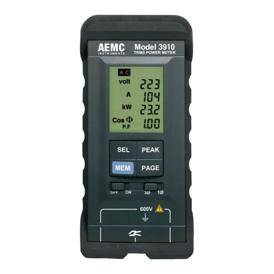
Description The True RMS Power Meter Model 3910 is designed for today’s electrical environments. Operation is simple. There are no programming require- ments or menus, just four push-buttons for direct access. The Model 3910 is auto-ranging and ensures the best range for measurements. Troubleshooting and measuring power is done simply by connecting two voltage leads and clamping on the current probe. The Model 3910 is easier to operate than most DMMs and may even replace your multimeter for individual voltage or current measurements. Small and compact in its protective holster, the Model 3910 provides seven essential power measurement values. Four measurements are displayed at a time on its extra large multi-display LCD. The Model 3910 performs current and voltage measurements in True RMS, and provides immediate readings of power factor (PF), active power (kW), reactive power (kVar), apparent power (kVA) and frequency (Hz). -
Page 7: Control Features
Control Features TRMS Power Meter Model 3910... - Page 8 4. Clamp Input FRB socket for connecting the clamp-on current probe. Use only specified current probes, which have a voltage output (1mV 5. Display LCD (40x50mm), displays the seven measurements on two pages. NOTE: A beep sounds when the PAGE, PEAK, SEL or MEM button is pressed. 6. PEAK Button Selects “PEAK” measurement mode. 7. PAGE Button Displays Vrms, Arms, W, PF (or Cos Φ) on page 1 automatically; pressing PAGE gives access to Var, VA and Hz on page 2. 8. 1Ø / 3Ø Selects the type of network to be tested. • 1Ø: single-phase • 3Ø: balanced three-phase, three-wire 9. Voltage Inputs Two safety input terminals (4mm) for lead connection. Voltage mea- surement may be made up to 600V TRMS Power Meter Model 3910...
-
Page 9: Display Features
When this button is activated, PEAK values of a measurement can be displayed. To activate the PEAK mode, press the PEAK button once. The Model 3910 changes initially to peak current measurements and “PEAK A” is displayed. Press the SEL button to choose the desired parameter (A, W, V). The SEL button can only be used after the PEAK button has been activated. -
Page 10: 2.4.2 Memory Button
The Model 3910 stores all the measurements present when peak is selected. The first four measurements (V, A, W, PF) are displayed on page 1 and the following three measurements (Var, VA, Hz) on page 2 (press the PAGE button). For example, you can find the voltage, the power, etc., at the moment when current is at a peak. In PEAK mode, the typical acquisition time is 400ms. Each new peak is taken into account as long as the PEAK button is activated. To exit PEAK mode, press the PEAK button. 2.4.2 Memory Button This button has two functions: • First Function - Memory To store page 1 of the display, press the MEM button once. “MEM” will show on the display. Voltage, current, active power and power factor are stored. -
Page 11: Specifications
Typical Accuracy (and Phase Shift) with 500A Current Probe MD313: 25A: 5% of Reading (4°) 100A: 2% of Reading (2°) 500A: 2% of Reading (1.5°) Typical Accuracy (and Phase Shift) with 1000A Current Probe SD652: 50A: ± 0.9% of Reading (1.5°) 200A: ± 0.5% of Reading (0.5°) 1000A: ± 0.5% of Reading (0.5°) Resolution: 1 to 9.99A: 10mA 10 to 99.9A: 100mA 100 to 500A: 1A VOLTAGE (TRMS) Input Range: 0 to 600V Accuracy: 1 to 99.9V: 0.5% ± 0.6V 100 to 600V: 0.3% ± 2V Resolution: 0 to 99.9V: 0.1V, 100 to 600V: 1V TRMS Power Meter Model 3910... -
Page 12: Mechanical Specifications
Range: -0.00 (Lag) to +0.00 (Lead) Accuracy: Sum of the V and A accuracy plus the probe phase shift ACTIVE POWER Range: 30W to 300kW (600kW with SR652 probe) Accuracy: Sum of the V and A accuracy REACTIVE POWER Range: 0 to 300kVar (600kVar with SR652 probe) Accuracy: Sum of V and A accuracy @ Sin Φ = 1 plus the probe phase shift APPARENT POWER Range: 0 to 300kVA (600kVA with SR652 probe) Accuracy: Sum of the V and A accuracy Mechanical Specifications Display: 1.58 x 1.97" (40 x 50mm) multi-display LCD Power Supply: Four 1.5V AA alkaline batteries Low Battery Indicator: “BAT” on display Battery Life: 50 hours approx, continuous use TRMS Power Meter Model 3910... -
Page 13: Safety Specifications
Dimensions: 3.2 x 6.9 x 1.3" (80 x 175 x 32mm) - without holster 3.5 x 7.7 x 2.1" (90 x 195 x 54mm) - with holster Weight (with battery): 15 oz (400g) - without holster 17.6 oz (500g) - with holster Supplied 500A current probe: Accommodates two 500 MCM or one 750 MCM Safety Specifications Protection Level: EN 61010, Class II Protection Index: IP40 per IED 529 Max. Voltage Overload: 825Vrms, 1170Vpeak TRMS Power Meter Model 3910... -
Page 14: Operation
CHAPTER 4 OPERATION Single-Phase Networks WARNING: Maximum voltage rating 600V • Set the selector switch to the 1Ø position. • Connect the Model 3910 as shown in the diagram, with phase con- nected to the right terminal and the probe on phase. NOTE: Only clamp the current probe around one conductor. The arrow on the current probe should always point towards the load for correct polarity indication during power measurements. TRMS Power Meter Model 3910... -
Page 15: Balanced Three-Phase Networks
Balanced Three-Phase Networks WARNING: Maximum voltage rating 600V • Set the selector switch to the 3Ø position. • Connect the Model 3910 as shown in the diagram. Note that the cur- rent probe is clamped onto the conductor that is not connected to a voltage input. The Model 3910 will automatically display the system power on balanced three-phase, three-wire circuits (two wattmeter method). TRMS Power Meter Model 3910... -
Page 16: Three-Phase, Four-Wire Networks
Three-Phase, Four-Wire Networks WARNING: Maximum voltage rating 600V • Set the selector switch to the 1Ø position. • Connect the Model 3910 as shown for single-phase (phase-to-neutral) and measure on each phase. • Add all three readings for system total. Total W = W + W + W TRMS Power Meter Model 3910... -
Page 17: Using As A Voltmeter
Using as a Voltmeter WARNING: Maximum voltage rating 600V • Plug voltage leads into the safety input terminals. • The selector switch may be set at either 1Ø or 3Ø position. • Connect the Model 3910 as shown in the diagram below. Note: The Model 3910 may also measure DC volts. DC will be displayed on the LCD. TRMS Power Meter Model 3910... -
Page 18: Using As An Ammeter
Using as an Ammeter WARNING: Maximum voltage rating 600V • Connect the current probe to the FRB socket. • The selector switch may be set at either 1Ø or 3Ø position. • Connect the Model 3910 as shown in the diagram. • Only use the supplied current probes (MD313 or optional SR652) TRMS Power Meter Model 3910... -
Page 19: Measurements: Review Of Formulas Used
Measurements: Review of Formulas Used ∑ Vrms = RMS Voltage: ∑ Irms = RMS Current: ∑ Active Power: Vn.In VA = Vrms x Irms Apparent Power: PF = Power Factor: Var = Reactive Power: TRMS Power Meter Model 3910... -
Page 20: Maintenance
CHAPTER 5 MAINTENANCE Warning Use only factory specified replacement parts. AEMC will not be held ® responsible for any accident, incident, or malfunction following a repair done other than by its service center or by an approved repair center. • Do not allow water or other foreign substances into the instrument. • Disconnect the unit from all circuits and test cables before opening the case. Battery Replacement The TRMS Power Meter Model 3910 is powered by four 1.5V “AA” alka- line batteries. When the battery indicator shows that the batteries are low (“BAT” appears on the LCD), the batteries should be replaced. • Unplug the leads and the clamp from the instrument. •... -
Page 21: Repair And Calibration
NOTE: You must obtain a CSA# before returning any instrument. Technical and Sales Assistance If you are experiencing any technical problems, or require any assistance with the proper operation or application of your instrument, please call, fax or e-mail our technical support team: Contact: Chauvin Arnoux , Inc. d.b.a. AEMC Instruments ® ® Phone: (800) 945-2362 (Ext. 351) (603) 749-6434 (Ext. 351) Fax: (603) 742-2346 E-mail: techsupport@aemc.com TRMS Power Meter Model 3910... -
Page 22: Limited Warranty
® For full and detailed warranty coverage, please read the Warranty Coverage Information, which is attached to the Warranty Registration Card (if enclosed) or is available at www.aemc.com. Please keep the Warranty Coverage Information with your records. What AEMC Instruments will do: ®... - Page 24 02/18 99-MAN 100072 v3 Chauvin Arnoux , Inc. d.b.a. AEMC Instruments ® ® 15 Faraday Drive • Dover, NH 03820 USA • Phone: (603) 749-6434 • Fax: (603) 742-2346 www.aemc.com...
Need help?
Do you have a question about the 3910 and is the answer not in the manual?
Questions and answers