
Subscribe to Our Youtube Channel
Related Manuals for Beckhoff EPP3504-0023


Summary of Contents for Beckhoff EPP3504-0023
- Page 1 Short documentation | EN EPP3504-0023 4-channel measuring bridge,(SG) full/half/quarter bridge, 24 bit, 10 ksps 2023-02-21 | Version: 1.2...
-
Page 3: Table Of Contents
Electronic access to the BIC (eBIC)................. 12 2 Product group: EtherCAT P Box modules.................... 14 3 Product overview ............................ 15 EPP3504-0023 - Introduction ...................... 15 EPP3504-0023 - Technical data ..................... 16 3.2.1 EPP3504-0023 overview measurement ranges............... 18 3.2.2 Measurement ±10 V...................... 20 3.2.3... - Page 4 6.3.8 Import/Export of EtherCAT devices with SCI and XTI............ 186 EtherCAT basics ........................... 192 EtherCAT cabling – wire-bound .................... 192 General notes for setting the watchdog .................. 193 EtherCAT State Machine ...................... 195 CoE Interface .......................... 197 Version: 1.2 EPP3504-0023...
- Page 5 7.1.4 Tightening torques for plug connectors................ 206 Notes regarding connectors and wiring.................. 207 Note - Power supply ........................ 209 Notes on connection technology EPP3504-0023................ 210 Connectors ............................ 211 Accessories ........................... 212 Power supply, potential groups ..................... 213 Status LEDs .......................... 215 7.8.1...
- Page 6 Table of contents Version: 1.2 EPP3504-0023...
-
Page 7: Foreword
, XTS and XPlanar are registered trademarks of and licensed by Beckhoff Automation GmbH. Other designations used in this publication may be trademarks whose use by third parties for their own purposes could violate the rights of the owners. Patent Pending... -
Page 8: Safety Instructions
All the components are supplied in particular hardware and software configurations appropriate for the application. Modifications to hardware or software configurations other than those described in the documentation are not permitted, and nullify the liability of Beckhoff Automation GmbH & Co. KG. Personnel qualification This description is only intended for trained specialists in control, automation and drive engineering who are familiar with the applicable national standards. -
Page 9: Documentation Issue Status
Also see about this 2 Firmware compatibility [} 242] Version identification of EtherCAT devices 1.4.1 General notes on marking Designation A Beckhoff EtherCAT device has a 14-digit designation, made up of • family key • type • version • revision EPP3504-0023... -
Page 10: Beckhoff Identification Code (Bic)
Associated and synonymous with each revision there is usually a description (ESI, EtherCAT Slave Information) in the form of an XML file, which is available for download from the Beckhoff web site. From 2014/01 the revision is shown on the outside of the IP20 terminals, see Fig. “EL5021 EL terminal, standard IP20 IO device with batch number and revision ID (since 2014/01)”. -
Page 11: Fig. 2 Example Dmc 1P072222Sbtnk4P562D71Kel1809 Q1 51S678294
Further types of information and data identifiers are used by Beckhoff and serve internal processes. Structure of the BIC Example of composite information from positions 1 to 4 and with the above given example value on position 6. -
Page 12: Electronic Access To The Bic (Ebic)
Foreword An important component of the BIC is the Beckhoff Traceability Number (BTN, position 2). The BTN is a unique serial number consisting of eight characters that will replace all other serial number systems at Beckhoff in the long term (e.g. batch designations on IO components, previous serial number range for safety products, etc.). - Page 13 EtherCAT, the eBIC of the top-level device is located in the CoE object directory 0x10E2:01 and the eBICs of the sub-devices follow in 0x10E2:nn. Profibus/Profinet/DeviceNet… Devices Currently, no electronic storage and readout is planned for these devices. EPP3504-0023 Version: 1.2...
-
Page 14: Product Group: Ethercat P Box Modules
EtherCAT P Box modules are EtherCAT P slaves with degree of protection IP67. They are designed for operation in wet, dirty or dusty industrial environments. EtherCAT basics A detailed description of the EtherCAT system can be found in the EtherCAT system documentation. Version: 1.2 EPP3504-0023... -
Page 15: Product Overview
It has the same technological features as the ELM3x0x Terminals, i.e. all parameters can be set via EtherCAT using the CoE directory. The EPP3504-0023 is designed for use close to the measurement site in a protected environment and is therefore equipped with IP20 bridge connections. -
Page 16: Epp3504-0023 - Technical Data
Product overview EPP3504-0023 - Technical data Technical data EPP3504-0023 Analog inputs 4 channel (differential) Time relation between channels to each Simultaneous conversion of all channels in the box, other synchronous conversion between devices, if DistributedClocks will be used ADC conversion method ΔΣ... - Page 17 See chapter “Mounting and wiring”/ “Mounting”/ “Dimensions” [} 203] Mounting Directly on metallic, earthed structure screwed Note mounting Plug partly not within scope of delivery, see chapter Notes on connection technology EPP3504-0023 [} 210] Weight approx. 250 g Permissible ambient temperature range 0…+55 °C during operation Permissible ambient temperature range -25…+85 °C...
-
Page 18: Epp3504-0023 Overview Measurement Ranges
Product overview 3.2.1 EPP3504-0023 overview measurement ranges Measurement Connection tech- Mode Maximum value/ value nology range Voltage 2 wire ±10 V Extended ±10.737.. V Legacy ±10 V ±80 mV Extended ±85.9.. mV Legacy ±80 mV PT1000 2/3/4 wire 2000 Ω Legacy 266 °C... -
Page 19: Fig. 4 Overview Measurement Ranges, Bipolar
Error = TRUE is also displayed. The detection limit for Underrange/Overrange Error can be set in the CoE. In Legacy Range mode, an Underrange/Overrange event also leads to an Error in the PDO status. EPP3504-0023 Version: 1.2... -
Page 20: Measurement ±10 V
Noisedensity@1kHz < 1.41 Noise (with 50 Hz FIR filter) E < 9.0 ppm < 70 digits < 90.0 µV Noise, PtP < 1.5 ppm < 12 digits < 15.0 µV Noise, RMS Max. SNR > 116.5 dB Version: 1.2 EPP3504-0023... -
Page 21: Fig. 6 Representation ±10 V Measurement Range
Error = TRUE is also displayed. The detection limit for Underrange/Overrange Error can be set in the CoE. In Legacy Range mode, an Underrange/Overrange event also leads to an Error in the PDO status. EPP3504-0023 Version: 1.2... -
Page 22: Measurement ±80 Mv
Noisedensity@1kHz < 0.03 Noise (with 50 Hz FIR filter) E < 18.0 ppm < 141 digits < 1.44 µV Noise, PtP < 3.0 ppm < 23 digits < 0.24 µV Noise, RMS Max. SNR > 110.5 dB Version: 1.2 EPP3504-0023... -
Page 23: Fig. 7 Representation ±80 Mv Measurement Range
Error = TRUE is also displayed. The detection limit for Underrange/Overrange Error can be set in the CoE. In Legacy Range mode, an Underrange/Overrange event also leads to an Error in the PDO status. EPP3504-0023 Version: 1.2... -
Page 24: Rtd/Pt1000 Measurement
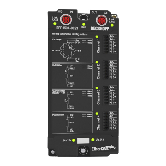
RTD type (Pt100, Pt1000…). Both steps can take place locally in the Beckhoff measurement device. The transformation in the device can also be deactivated if it is to be calculated on a higher level in the control. Depending on the device type, several RTD conversions can be implemented which only differs in software. - Page 25 • Full bridge: 4‑wire connection without line compensation, 6‑wire connection with full line compensation • Half bridge: 3‑wire connection without line compensation, 5‑wire connection with full line compensation • Quarter bridge: 2‑wire connection without line compensation, 3‑wire connection with theoretical line compensation and 4‑wire connection with full line compensation EPP3504-0023 Version: 1.2...
- Page 26 0 … 2 kΩ PDO LSB (Extended Range) Extended range is not supported for resistance measurement PDO LSB (Legacy Range) Resistance measurement not available as separate measuring range on EPP3504-0023. Preliminary specifications: Resistance measurement 2kΩ 2/3-wire 4-wire Basic accuracy: Measuring deviation at <...
-
Page 27: Fig. 8 Chart: Rtd Measuring Range
• equations for calculating further parameters (offset/gain/non-linearity/repeatability/noise) if necessary from the resistance specification at the desired operating point RTD types supported by the EPP3504-0023: EPP3504-0023 Version: 1.2... -
Page 28: Fig. 10 Diagram For Basic Accuracy For Pt1000, 3-Wire Connection
)) / (ΔR Temp Measuring point Resistance Measuring point proK Measuring point • To determine the error of the entire system consisting of RTD and the measuring device in [°C], the two errors must be added together quadratically: Version: 1.2 EPP3504-0023... - Page 29 ) = 0.074 Ω / 4.05 Ω/°C ≈ 0.018 °C (means ± 0.018 °C) Temp Measuring point Example 4: If the noise E of the above example terminal is considered not for one sensor point -100 °C but in Noise, PtP general, the following plot results: EPP3504-0023 Version: 1.2...
-
Page 30: Fig. 12 Diagram Noise Enoise, Ptp In Dependence On Sensor Temperature
Product overview Fig. 12: Diagram noise E in dependence on sensor temperature Noise, PtP Version: 1.2 EPP3504-0023... -
Page 31: Potentiometer Measurement
Noise (with 50 Hz FIR filter, at < 9.0 ppm Noise, PtP 23°C) < 70 digits < 1.5 ppm Noise, RMS < 12 digits Max. SNR > 116.5 dB Common-mode rejection ratio (without filter) 50 Hz: 1 kHz: typ. typ. typ. EPP3504-0023 Version: 1.2... -
Page 32: Fig. 13 Representation Potentiometer Measurement Range
In practice, the offset component can be eliminated by the functions Tare and also ZeroOffset [} 000] of the box module or in the controller by a higher-level tare function. The offset deviation over time can change, therefore Beckhoff recommends a regular offset adjustment or careful observation of the change. -
Page 33: Measurement Sg 1/1 Bridge (Full Bridge) 4/6-Wire Connection
3.2.6 Measurement SG 1/1 bridge (full bridge) 4/6-wire connection Some notes to EPP3504-0023 full bridge measurement: The nominal/technical measuring range is specified in "mV/V"; the maximum permitted supply voltage is 5 V. The maximum nominal measuring range that can be used for the bridge voltage is therefore ±32 mV/ V ⋅ 5 V = ±160 mV;... - Page 34 Product overview The strain relationship (µStrain, µε) is as follows: Version: 1.2 EPP3504-0023...
- Page 35 < 20 ppm < 30 ppm < 40 ppm < 40 ppm < 80 ppm Common- mode tbd. tbd. tbd. tbd. tbd. tbd. rejection ratio 50 Hz (without filter) tbd. tbd. tbd. tbd. tbd. tbd. 1 kHz tbd. tbd. tbd. tbd. tbd. tbd. EPP3504-0023 Version: 1.2...
- Page 36 Features [} 000] of the box module or in the controller by a higher-level tare function. The offset deviation of a bridge measurement over time can change, therefore Beckhoff recommends a regular offset adjustment or careful observation of the change.
- Page 37 < 20.0 ppm Noise, RMS < 16 digits < 39 digits < 78 digits < 156 digits < 0.06 µV/V < 0.04 µV/V < 0.04 µV/V < 0.04 µV/V Max. > 114.0 dB > 106.0 dB > 100.0 dB > 94.0 dB EPP3504-0023 Version: 1.2...
-
Page 38: Measurement Sg 1/2 Bridge (Half Bridge) 3/5-Wire Connection
3.2.7 Measurement SG 1/2 bridge (half bridge) 3/5-wire connection Some notes to EPP3504-0023 half bridge measurement: The nominal/technical measuring range is specified in "mV/V"; the maximum permitted supply voltage is 5 V. The maximum nominal measuring range that can be used for the bridge voltage is therefore ±16 mV/ V ⋅ 5 V = ±80 mV;... - Page 39 The strain relationship (µStrain, µε) is as follows: N should be chosen based on the mechanical configuration of the variable resistors (Poisson, 2 active uniaxial, …). The channel value (PDO) is interpreted directly [mV/V]. EPP3504-0023 Version: 1.2...
- Page 40 < 50 ppm < 100 ppm < 240 ppm < 100 ppm < 200 ppm Common- mode tbd. tbd. tbd. tbd. tbd. tbd. rejection ratio 50 Hz (without filter) tbd. tbd. tbd. tbd. tbd. tbd. 1 kHz tbd. tbd. tbd. tbd. tbd. tbd. Version: 1.2 EPP3504-0023...
- Page 41 Features [} 000] of the box module or in the controller by a higher-level tare function. The offset deviation of a bridge measurement over time can change, therefore Beckhoff recommends a regular offset adjustment or careful observation of the change.
- Page 42 The resistor of the bridge is positioned parallel to the internal resistor of the box module and leads to an offset shifting respectively. The Beckhoff factory calibration will be carried out with the half bridge 350 Ω, thus the values specified above are directly valid for the 350 Ω half bridge. By connection of another dimensioned half-bridge is to: •...
-
Page 43: Measurement Sg 1/4 Bridge (Quarter-Bridge) 2/3-Wire Connection
Only 3-wire operation should be used. • Specifications apply to 5 V excitation. The specification deteriorates at lower excitation voltage; Beckhoff does not have detailed information on this. If a lower excitation voltage is desired for reasons of sensor self-heating, the excitation voltage can be temporarily switched on/off for non-continuous measurements (clocked operation). -
Page 44: Fig. 14 Connection Of The Quarter Bridge
• Rs: switchable shunt resistor • SW: internal switch for 2/3-wire operation; open: 3-wire operation The strain relationship (µStrain, µε) is as follows: For the quarter-bridge, N=1 always applies. The relationship between U and ∆R is non-linear: Bridge Version: 1.2 EPP3504-0023... -
Page 45: Fig. 15 Relationship Between Ubridge/Uexc And ∆R1
Product overview Fig. 15: Relationship between UBridge/UExc and ∆R The EPP3504‑0023 devices apply internal linearization so that the output is already linearized since the internal calculation is based on U Exc' EPP3504-0023 Version: 1.2... - Page 46 < 2.88 µV/V/K < 2.88 µV/V/K < 2.88 µV/V/K Largest short-term tbd. % tbd. % tbd. % tbd. % deviation during a specified electrical interference test Input Differential tbd. tbd. tbd. tbd. impedance CommonM tbd. tbd. tbd. tbd. ±Input 1 Version: 1.2 EPP3504-0023...
- Page 47 < ±0.044% < ±0.16% < ±0.32% < ±0.64% accuracy: Offset < ±440 ppm < ±1600 ppm < ±3200 ppm < ±6400 ppm Measuring < ±14 µV/V < ±12.8 µV/V < ±12.8 µV/V < ±12.8 µV/V deviation at EPP3504-0023 Version: 1.2...
- Page 48 < 2500 digits < 5000 digits < 1.6 µV/V < 1.28 µV/V < 1.28 µV/V < 1.28 µV/V Max. > 86.0 dB > 75.9 dB > 69.9 dB > 63.9 dB Noiseden sity@1kH < 0.02 < 0.02 < 0.02 < 0.02 Version: 1.2 EPP3504-0023...
- Page 49 < 36.0 ppm Noise, RMS < 23 digits < 70 digits < 141 digits < 281 digits < 0.1 µV/V < 0.07 µV/V < 0.07 µV/V < 0.07 µV/V Max. > 110.5 dB > 100.9 dB > 94.9 dB > 88.9 dB EPP3504-0023 Version: 1.2...
- Page 50 < 3.68 µV/V/K < 3.68 µV/V/K < 3.68 µV/V/K Largest short-term tbd. % tbd. % tbd. % tbd. % deviation during a specified electrical interference test Input Differential tbd. tbd. tbd. tbd. impedance CommonM tbd. tbd. tbd. tbd. ±Input 1 Version: 1.2 EPP3504-0023...
- Page 51 Features [} 000] of the box module or in the controller by a higher-level tare function. The offset deviation of a bridge measurement over time can change, therefore Beckhoff recommends a regular offset adjustment or careful observation of the change.
-
Page 52: Process Data Interpretation
The channel for this box module features an option to set the measuring range either to the conventional Beckhoff type, up until now: "nominal full-scale value = PDO end value: LegacyRange" or the new method "technical full-scale value = PDO end value: ExtendedRange". -
Page 53: General Information On Measuring Accuracy/Measurement Uncertainty
Depending on the work involved, the measurement/measured value is subject to a random measuring error that cannot be eliminated. With its practically determined specification data, Beckhoff provides an approach that can be used to calculate the residual measurement uncertainty in the individual case. The following paragraphs elucidate this. - Page 54 CoE object 0xF900:02 [} 81]. This can be evaluated by an application, • in horizontal installation position, taking the minimum distances into consideration, • under natural convection (no forced ventilation), • provided the specifications are adhered to. Version: 1.2 EPP3504-0023...
- Page 55 The independent specification data can be divided into two groups: • the data on offset/gain deviation, non-linearity, and repeatability, whose effect on the measurement cannot be influenced by the user. These are summarized by Beckhoff according to the calculation below, at "basic accuracy at 23°C".
- Page 56 Error coefficient of ageing If the specification value for aging from Beckhoff has not (yet) been specified, it must be assumed to be 0 ppm when considering measurement uncertainty, as in the above example, even if in reality it can be assumed that the measurement uncertainty of the device under consideration changes over the operating time, or colloquially stated, the measured value "drifts".
- Page 57 This value could easily be calculated from the data given by the specification, as the total accuracy consists of a measured value and full scale value dependent component and an exclusively full scale value dependent component, according to the formula: EPP3504-0023 Version: 1.2...
-
Page 58: Scope Of Supply
Product overview Scope of supply Make sure that the following components are included in the scope of delivery: • 1x EtherCAT P Box EPP3504-0023 • 2x protective cap for EtherCAT P socket, M8, red (pre-assembled) • 4x label, blank Pre-assembled protective caps do not ensure IP67 protection Protective caps are pre-assembled at the factory to protect connectors during transport. -
Page 59: Commissioning
Commissioning Commissioning Notes to short documentation NOTE This short documentation does not contain any further information within this chapter. For the complete documentation please contact the Beckhoff sales department responsible for you. EPP3504-0023 Version: 1.2... -
Page 60: Coe Overview
If values are to be changed or read specifically at application runtime, function blocks (FBs) can be used for CoE access to the TwinCAT TC2_EtherCAT.lib. See also the sample programs in this documentation. Single access and CompleteAccess are possible. Version: 1.2 EPP3504-0023... -
Page 61: Fig. 18 Function Blocks (Fbs) For Coe Access To The Twincat Tc2_Ethercat.lib
Fig. 18: Function blocks (FBs) for CoE access to the TwinCAT TC2_EtherCAT.lib TwinCAT TF6010 ADS Monitor The TF6010 ADS Monitor is a free tool from Beckhoff for monitoring ADS communication. It can be used to read or write CoE values from/to the EtherCAT device (Command Test). Single access and CompleteAccess are possible. -
Page 62: Fig. 20 Filter Coefficients Nos. 1 To 12 Of Channel 1 In The Coe Online Of An Elm3602 Ethercat Ter- Minal
"in one set", alternatively they could also be copied out manually one after the other as above. After installing the TF6010 ADS Monitor from the Beckhoff website, it can be started in the development environment menu under [TwinCAT] → [ADS Monitor]: Version: 1.2... -
Page 63: Fig. 22 Calling The Ads Monitor Command Test
TwinCAT must be activated or restarted. Fig. 23: Activation of "EtherCAT Addr." The following is to be entered in the dialog: • A: Ams Net ID of the EtherCAT master • B: as port, the EtherCAT address of the 'Slave' EPP3504-0023 Version: 1.2... - Page 64 Which corresponds exactly to the values from figure above "Filter coefficients nos. 1 to 12 of channel 1 in CoE-Online of an ELM3602 EtherCAT Terminal". The values can thus be further processed using a spreadsheet program and, if necessary, incorporated into a self-generated Startup.xml. Version: 1.2 EPP3504-0023...
-
Page 65: 0X10E2 Manufacturer-Specific Identification Code
TRUE: Measurement event overflow BOOLEAN 0x00 (0 60n0:0D Diag TRUE: New diagnostic message BOOLEAN 0x00 (0 available 60n0:0E TxPDO State TRUE: data invalid BOOLEAN 0x00 (0 60n0:0F Input cycle Incremented by one when values have BIT2 0x00 (0 counter changed EPP3504-0023 Version: 1.2... -
Page 66: 0X60N1 Pai Samples Ch.[N+1] (24 Bit)
0 ≤ n ≤ m, n+1 = Channel number, m+1 = max. No. of channels Index Name Meaning Data type Flags Default (hex) 60n5:0 PAI Timestamp UINT8 0x02 (2 Ch.[n+1] 60n5:01 Low Timestamp (low) UINT32 0x00000000 60n5:02 Hi Timestamp (hi) UINT32 0x00000000 Version: 1.2 EPP3504-0023... -
Page 67: 0X60N6 Pai Synchronous Oversampling Ch.[N+1]
Sensor supply: UINT16 0x0000 (0 0 - 0.0 V 2 - 1.0 V 3 - 1.5 V 4 - 2.0 V 5 - 2.5 V 6 - 3.0 V 7 - 3.5 V 8 - 4.0 V EPP3504-0023 Version: 1.2... - Page 68 Average Filter 2 80n0:1B True RMS No. Number of samples for "True RMS" UINT16 0x0001 (1 of Samples calculation (min. 1, max. 1000); also see chapter TrueRMS 80n0:1C Enable True Activation of "True RMS" BOOLEAN 0x00 (FALSE) calculation Version: 1.2 EPP3504-0023...
- Page 69 Low load cycle limit REAL32 0xFF7FFFFD Limit (-3.4028231e+38) 80n0:3B High Load Cycle High load cycle limit REAL32 0x7F7FFFFD Limit (3.4028231e+38) 80n0:40 Filter 1 Type Filter 1 type information STRING Info 80n0:41 Filter 2 Type Filter 2 type information STRING Info EPP3504-0023 Version: 1.2...
-
Page 70: 0X80N1 Pai Filter 1 Settings Ch.[N+1]
LookUp y value 1 80n6:03 Scaler Value 3 LookUp x value 2 REAL32 0x00000000 (0 80n6:04 Scaler Value 4 LookUp y value 2 REAL32 0x00000000 (0 80n6:63 Scaler Value 99 LookUp x value 50 REAL32 0x00000000 (0 80n6:64 Scaler Value 100 LookUp y value 50 REAL32 0x00000000 (0 Version: 1.2 EPP3504-0023... -
Page 71: 0X80Na Pai Extended Settings Ch.[N+1]
(T1S1 * temp * sample) 80nE:09 T2 Temperature coefficient for second- REAL32 0x00000000 order temperature value (0.0 (T2 * temp²) 80nE:0A T2S1 Combined coefficient for second-order REAL32 0x00000000 gain and temperature values (0.0 (T2S1 * temp² * sample) EPP3504-0023 Version: 1.2... -
Page 72: 0X80Nf Pai Vendor Calibration Data Ch.[N+1]
(T2S1 * temp² * sample) 80nF:0B T3 Temperature coefficient for third-order REAL32 0x00000000 temperature value (0.0 (T3 * temp³) 80nF:0C T3S1 Combined coefficient for third-order REAL32 0x00000000 gain and temperature values (0.0 (T3S1 * temp³ * sample) Version: 1.2 EPP3504-0023... -
Page 73: 0X90N0 Pai Internal Data Ch.[N+1]
4.2.19 0x90n2 PAI Info Data Ch.[n+1] 0 ≤ n ≤ m, n+1 = Channel number, m+1 = max. No. of channels Index Name Meaning Data type Flags Default (hex) 90n2:0 PAI Info Data UINT8 0x12 (18 Ch.[n+1] EPP3504-0023 Version: 1.2... - Page 74 Counter of the user calibration UINT16 0x0000 Counter (related to the selected interface) The counter counts +1 when data has changed and the memory code word is written. Depending on the adjustment method, the counter may therefore count several times. Version: 1.2 EPP3504-0023...
-
Page 75: 0X90Nf Pai Calibration Dates Ch.[N+1]
OCTET-STRING[4] 3Wire 4 mV/V 90nF:18 Vendor SG Half-Bridge OCTET-STRING[4] 3Wire 4 mV/V compensated 90nF:19 Vendor SG Half-Bridge OCTET-STRING[4] 3Wire 8 mV/V 90nF:1A Vendor SG Half-Bridge OCTET-STRING[4] 3Wire 16 mV/V 90nF:1B Vendor SG Half-Bridge OCTET-STRING[4] 5Wire 2 mV/V EPP3504-0023 Version: 1.2... - Page 76 90nF:30 Vendor SG Quarter-Bridge OCTET-STRING[4] 2Wire 350R 4 mV/V compensated 90nF:31 Vendor SG Quarter-Bridge OCTET-STRING[4] 2Wire 350R 8 mV/V 90nF:32 Vendor SG Quarter-Bridge OCTET-STRING[4] 2Wire 350R 32 mV/V 90nF:33 Vendor SG Quarter-Bridge OCTET-STRING[4] 3Wire 350R 2 mV/V Version: 1.2 EPP3504-0023...
- Page 77 User PT1000 3 Wire OCTET-STRING[4] 90nF:86 User PT1000 4 Wire OCTET-STRING[4] 90nF:87 User Poti 3 Wire OCTET-STRING[4] 90nF:88 User Poti 5 Wire OCTET-STRING[4] 90nF:89 User SG Full-Bridge 4Wire OCTET-STRING[4] 2 mV/V 90nF:8A User SG Full-Bridge 4Wire OCTET-STRING[4] 2 mV/V compensated EPP3504-0023 Version: 1.2...
- Page 78 User SG Quarter-Bridge OCTET-STRING[4] 2Wire 120R 2 mV/V 90nF:A2 User SG Quarter-Bridge OCTET-STRING[4] 2Wire 120R 2 mV/V compensated 90nF:A3 User SG Quarter-Bridge OCTET-STRING[4] 2Wire 120R 4 mV/V 90nF:A4 User SG Quarter-Bridge OCTET-STRING[4] 2Wire 120R 4 mV/V compensated Version: 1.2 EPP3504-0023...
- Page 79 90nF:B8 User SG Quarter-Bridge OCTET-STRING[4] 3Wire 350R 32 mV/V 90nF:B9 User SG Quarter-Bridge OCTET-STRING[4] 2Wire 1k 2 mV/V 90nF:BA User SG Quarter-Bridge OCTET-STRING[4] 2Wire 1k 2 mV/V compensated 90nF:BB User SG Quarter-Bridge OCTET-STRING[4] 2Wire 1k 4 mV/V EPP3504-0023 Version: 1.2...
-
Page 80: 0Xf000 Modular Device Profile
4.2.22 0xF008 Code word Index Name Meaning Data type Flags Default (hex) F008:0 Code word UINT32 0x00000000 4.2.23 0xF009 Password Protection Index Name Meaning Data type Flags Default (hex) F009:0 Password UINT32 0x00000000 protection Version: 1.2 EPP3504-0023... -
Page 81: 0Xf010 Module List
= number of existing channels by the box module 4.2.25 0xF083 BTN Index Name Meaning Data type Flags Default (hex) F083:0 Beckhoff Traceability Number STRING 00000000 4.2.26 0xF900 PAI Info Data Index Name Meaning Data type Flags Default (hex) -
Page 82: 0Xfb00 Pai Command
(100 = 0% etc.) 255: function is busy, if [100..200] won’t be used as progress display FB00:03 Response Command response OCTET- STRING[6] If the transferred command returns a response, it will be displayed here. Functional dependent, see resprective sections. Version: 1.2 EPP3504-0023... -
Page 83: 0X80N0:01 Pai Settings.interface
524 - SG Quarter-Bridge 2Wire 1k 32 mV/V 548 - SG Quarter-Bridge 3Wire 1k 2 mV/V compensated 550 - SG Quarter-Bridge 3Wire 1k 4 mV/V compensated 551 - SG Quarter-Bridge 3Wire 1k 8 mV/V 556 - SG Quarter-Bridge 3Wire 1k 32 mV/V EPP3504-0023 Version: 1.2... -
Page 84: Sample Programs
• The EtherCAT device of the example should usually be declared your present system. After selection of the EtherCAT device in the “Solutionexplorer” select the “Adapter” tab and click on “Search...”: Fig. 25: Search of the existing HW configuration for the EtherCAT configuration of the example Version: 1.2 EPP3504-0023... -
Page 85: Sample Program 1 And 2 (Offset/Gain)
CoE directory ("PAI Scaler Settings" object) can be done in this sample program (see Variable declaration). The following procedure is foreseen: 1. Configuration of "bWriteToCoEEnable" = TRUE, i.e. on completion of the calculation of the correction values, they are written to the CoE object "PAI Scaler Settings". EPP3504-0023 Version: 1.2... - Page 86 Example program 1 and 2 program code: PROGRAM MAIN VAR_INPUT bEnable :BOOL; // Start the code (Offset / Gain adjust) nPAI_Sample AT%I* :DINT; // Input samples of the measurement value END_VAR // Enter your Net-Id here: userNetId :T_AmsNetId := 'a.b.c.d.x.y'; // Enter EtherCAT device address here: nUserSlaveAddr :UINT := 1002; // Check, if correct // Configurations: fMinFrequencyIn :REAL:=1.5; // Hz bScalingOrder :BOOL:=FALSE; // TRUE: Start scale offset first bWriteToCoEEnable :BOOL:=FALSE; // TRUE: Enable writing to CoE // =============================================== // "Main" State controlling Offset/Gain adjusting: nMainCal_State :BYTE:=0; // For CoE Object 0x8005 access: fb_coe_write :FB_EcCoESdoWrite; // FB for writing to CoE nSTATE_WRITE_COE :BYTE := 0; nSubIndex :BYTE; nCoEIndexScaler :WORD := 16#8005; // Use channel 1 // For EPP3504‑0023 this is 0x8006 nSubIndScalGain :BYTE := 16#02; nSubIndScalOffs :BYTE := 16#01; nADSErrId :UDINT; // Copy of ADS-Error ID // =============================================== fb_get_min_max :FB_GET_MIN_MAX; // Min/Max values needed // Note: you may also use "FB_ALY_MinMaxAvg_1Ch" of TwinCAT analytics) // instead; there avg (average values can also be determinated // Variables used for offset scaling: Version: 1.2 EPP3504-0023...
- Page 87 bError :BOOL := FALSE; // Evaluate.. END_VAR Execution part: // THIS CODE IS ONLY AN EXAMPLE - YOU HAVE TO CHECK APTITUDE FOR YOUR APPLICATION // Example program 1 and 2 program code: // ===================================== // 1. PAI setting of 0x80n0:2E must be "Extended Range" at first // 2. When writing of scaling values were done, switch to "Linear" // Calculation of the temporary value (..and use for ScopeView to check) nScaledSampleVal := nOffset + nGain * DINT_TO_REAL(nPAI_Sample); // Main-State Procedure: CASE nMainCal_State OF 0: fb_trig_bEnable(CLK:=(bEnable AND NOT bError)); IF fb_trig_bEnable.Q THEN // Poll switch or button // Initialize temporary offset and gain values: nOffset:= 0; nGain := 1; bScaleOffsetStart := bScalingOrder; bScaleGainStart := NOT bScalingOrder; fb_get_min_max.nMinFreqInput := fMinFrequencyIn; nMainCal_State := 10; // Start END_IF 10: IF (bScaleGainDone AND NOT bScalingOrder) OR (bScaleOffsetDone AND bScalingOrder) THEN bScaleOffsetStart := NOT bScalingOrder; bScaleGainStart := bScalingOrder; nMainCal_State := nMainCal_State + 10; END_IF 20: IF bScaleGainDone AND bScaleOffsetDone THEN nMainCal_State :=0; // All done, initalization for next start EPP3504-0023 Version: 1.2...
- Page 88 fOffsetDeviationVal := (fb_get_min_max.nMaxVal - ABS((fb_get_min_max.nMaxVal-fb_get_min_max.nMinVal)/2)); // Offset deviation check: IF ABS(fOffsetDeviationVal) < nOFFSET_MIN_VAL_REF THEN // Deviation in acceptable range - offset scaling done, // now write correction value into CoE Object: nDINT_Value := REAL_TO_DINT(nOffset); // Initiate writing to CoE: nSubIndex := nSubIndScalOffs; nSTATE_WRITE_COE := 10; nSTATE_SCALE_OFFSET := nSTATE_SCALE_OFFSET + 10; ELSE // Calculate new offset value (new by old with deviation) nOffset := nOffset - fOffsetDeviationVal; END_IF END_IF 10: IF(nSTATE_WRITE_COE = 0) THEN // Scaling offset done within CoE of the device bScaleOffsetDone := TRUE; bScaleOffsetStart := FALSE; nSTATE_SCALE_OFFSET := 0; END_IF END_CASE END_IF // ----- Gain scaling (program 2) ----- IF bScaleGainStart THEN CASE nSTATE_SCALE_GAIN OF 0: bScaleGainDone := FALSE; // Initialization of confirmation flag // Get min/max values within a period of the signal: fb_get_min_max(nInputValue:=DINT_TO_REAL(nPAI_Sample)); IF fb_get_min_max.bRESULT THEN // Wait if Limit-Values are valid // Calculate Gain nGain := nPRESET_MAX_VAL/ABS((fb_get_min_max.nMaxVal-fb_get_min_max.nMinVal)/2); // ..shift gain value by 16 Bit left and convert to DINT: nDINT_Value := REAL_TO_DINT(65536 * nGain); Version: 1.2 EPP3504-0023...
- Page 89 END_IF nSTATE_SCALE_GAIN := nSTATE_SCALE_GAIN + 10; END_IF 20: IF(nSTATE_WRITE_COE = 0) THEN // Scaling gain done within CoE of the device bScaleGainStart := FALSE; bScaleGainDone := TRUE; nSTATE_SCALE_GAIN := 0; // Set initial state END_IF END_CASE END_IF IF (nSTATE_WRITE_COE > 0) THEN IF bWriteToCoEEnable THEN CASE nSTATE_WRITE_COE OF 10: // Prepare CoE write access fb_coe_write( sNetId:= userNetId, nSlaveAddr:= nUserSlaveAddr, nIndex:= nCoEIndexScaler, bExecute:= FALSE, tTimeout:= T#1S ); nSTATE_WRITE_COE := nSTATE_WRITE_COE + 10; 20: // Write nDINT_Value to CoE Index "Scaler": fb_coe_write( nSubIndex:= nSubIndex, pSrcBuf:= ADR(nDINT_Value), cbBufLen:= SIZEOF(nDINT_Value), bExecute:= TRUE ); nSTATE_WRITE_COE := nSTATE_WRITE_COE + 10; 30: fb_coe_write(); IF NOT fb_coe_write.bBusy THEN EPP3504-0023 Version: 1.2...
- Page 90 Function block FB_GET_MIN_MAX Declaration part: FUNCTION_BLOCK FB_GET_MIN_MAX VAR CONSTANT CMAXinit :REAL := -3.402823E+38; CMINinit :REAL := 3.402823E+38; END_VAR VAR_INPUT bInit :BOOL := TRUE; nInputValue :REAL; nMinFreqInput :REAL; END_VAR VAR_OUTPUT bRESULT :BOOL; nMaxVal :REAL; nMinVal :REAL; END_VAR CMMcnt :UINT; nMaxValCnt :UINT; nMinValCnt :UINT; bValidMinVal :BOOL; bValidMaxVal :BOOL; fbGetCurTaskIdx : GETCURTASKINDEX; END_VAR Execution part: IF bInit THEN // Counter initialization: // [counter value] > [1/(<input frequency> * TaskCycleTime)] fbGetCurTaskIdx(); CMMcnt := REAL_TO_UINT( 1.1E7/(nMinFreqInput*UDINT_TO_REAL( _TaskInfo[fbGetCurTaskIdx.index].CycleTime))); // At least an entire period have to be sampled for min/max determination Version: 1.2 EPP3504-0023...
-
Page 91: Sample Program 3 (Write Lookup Table)
bRESULT := NOT (nMaxVal = nMinVal); // Sign valid results ELSE bRESULT := FALSE; // Sign still invalid results END_IF 4.3.2 Sample program 3 (write LookUp table) Download TwinCAT 3 project: https://infosys.beckhoff.com/content/1033/epp3504/Resources/ 2152669707/.zip Program description Transmission of LookUp table interpolation values for mapping of an equation f(x) = x via CoE into the box module. Variable declaration sample program 3 PROGRAM MAIN... - Page 92 • The variable "userSlaveAddr" must contain the EtherCAT address of the box module. Sample program for transferring the LookUp table: Execution part: // Example program 3: // ###### Write LookUp table into CoE object 0x8005: ####### IF bWriteLUT2CoE THEN CASE wState OF 0: fb_coe_writeEx(bExecute := FALSE);// Prepare CoE-Access wState := wState + 1;// Next state 1: // Write 100 X/Y LookUp-Table entries fb_coe_writeEx( sNetId:= userNetId, nSlaveAddr:= userSlaveAddr, nSubIndex:= 1, nIndex:= wCoEIndexScaler, pSrcBuf:= ADR(aLUT), cbBufLen:= SIZEOF(aLUT), bCompleteAccess:= TRUE, bExecute:= TRUE ); wState := wState + 1; // Next state Version: 1.2 EPP3504-0023...
-
Page 93: Sample Program 4 (Generate Lookup Table)
bWriteLUT2CoE := TRUE; END_IF 4.3.3 Sample program 4 (generate LookUp table) Download TwinCAT 3 project: https://infosys.beckhoff.com/content/1033/epp3504/Resources/ 2152669707/.zip Program description / function: Inclusion of LookUp table interpolation values from a box module input signal to a field variable (and optional subsequent transfer of the LookUp table interpolation values via CoE access to the box module using sample program 3). -
Page 94: Sample Program 5 (Write Filter Coefficients)
nYstepValue := (nMaxValue - nMinValue) / nEndX; // Y steps nYvalue := aValues[0]; // Common start value of the LUT FOR nX:=0 TO nEndX DO // Create LUT (X = actual values, Y = target values): aLUT[nX*2] := aValues[nX]; // X value aLUT[nX*2+1] := nYvalue; // Y value // next Y value of the LUT (make a "straight"): nYvalue := nYvalue + nYstepValue; // f(x) = b+x END_FOR END_IF END_IF 4.3.4 Sample program 5 (write filter coefficients) Download TwinCAT 3 project: https://infosys.beckhoff.com/content/1033/epp3504/Resources/ 2152672011/.zip Version: 1.2 EPP3504-0023... - Page 95 // Writing PLC state for coefficients transfer (Set to 0 for start) wState :BYTE:=255; index :BYTE:=1; // Start index for coefficients transfer wCoEIndexUserFilterCoeffizents :WORD:=16#8001; aFilterCoeffs:ARRAY[0..NumOfFilterCoeff] OF LREAL := [ // Example filter coefficients FIR band pass: 3600..3900 Hz // Usage: "User defined FIR Filter" (32) 0.03663651655662163, 0.04299467480848277, -0.007880289104928245, 0.0664029021294729, -0.0729038234874446, -0.00005849791174519834, 0.05628409460964408, -0.0525134329294473, 0.026329003448584205, 0.00027114381194760643, -0.03677629552114248, 0.06743018479714939, -0.0560894442193289, 0.0009722394088121363, 0.05676876756757213, -0.07775650809213645, 0.05330627422911416, 0.0009941073749156226, -0.055674804078696793, 0.07874009379691002, -0.055674804078696793, 0.0009941073749156226, 0.05330627422911416, -0.07775650809213645, EPP3504-0023 Version: 1.2...
- Page 96 END_VAR Execution part: // Example program 5: // writes filter coefficients of // "User defined FIR Filter" (32) // incl. example coefficients for band pass // Note: writing possible, if CoE Object // PAI Settings Ch.1 (0x8000:16) has value 32 or 33 set, only! // (32 = User defined FIR Filter / 33 = User defined IIR Filter) // =============================================================== CASE wState OF 0: fb_coe_write(bExecute := FALSE);// Prepare CoE access wState := wState + 1;// Go to next state 1: //nValue := REAL_TO_DINT(DINT_TO_REAL(aFilterCoeffs[index]) *16384); nValue := LREAL_TO_DINT(aFilterCoeffs[index] * 1073741824); // Bit-shift factor: 2^30 // Write filter coefficients (max. 40 entries) fb_coe_write( sNetId:= userNetId, nSlaveAddr:= userSlaveAddr, nSubIndex:= index, nIndex:= wCoEIndexUserFilterCoeffizents, pSrcBuf:= ADR(nValue), cbBufLen:= SIZEOF(nValue), bExecute:= TRUE, tTimeout:= T#1S ); wState := wState + 1; // Go to next state 2: // Execute writing to CoE fb_coe_write(); IF fb_coe_write.bError THEN wState := 100; // Error case ELSE Version: 1.2 EPP3504-0023...
-
Page 97: Sample Program 6 (Interlacing Of Measured Values)
(in this case: 50 µs). If the two measured data streams are now combined alternately in the controller, i.e. "interlaced", the result is a net measured data stream of 20 ksps. Fig. 26: Process of interlacing the input data The following configuration is used for this purpose: EPP3504-0023 Version: 1.2... -
Page 98: Fig. 27 Configuration And Setup For Sample Program 6: Doubling Of The Sample Rate With 2 X El3751
50 µs for the second terminal. This is set in the "Advanced settings" for Distributed Clocks ("DC" tab) for the second terminal: Fig. 28: Setting the DC shift time for terminal 2 Version: 1.2 EPP3504-0023... - Page 99 Sample program This setting, like the base time and the task cycle time, is already configured in the sample program: Download TwinCAT 3 project / sample program 6a: https://infosys.beckhoff.com/content/1033/epp3504/ Resources/4867888523/.zip In the following section, the simplest form of input value interlacing in Structured Text is initially shown with oversampling = 1 for each input value: each of two elements of a field variable receives a value from a...
-
Page 100: Fig. 29 Oversampling 20 Ksps With 2 X El3751 With Input Signals (Below) And Result Signal (Top)
For this purpose the sample program contains an additional task with 50 µs cycle time, which is required for representing the input signals in the SopeView and contains a variable (nCollected) to which both inputs are assigned alternately: // 50 µs task Version: 1.2 EPP3504-0023... -
Page 101: Sample Program 7 (General Decimation In The Plc)
aCollectedResult[2*nPos] := aSamples_1[nPos]; // Put n-th value of sequence into array (2nd here): aCollectedResult[2*nPos+1] := aSamples_2[nPos]; END_FOR Download TwinCAT 3 project / sample program 6b: https://infosys.beckhoff.com/content/1033/epp3504/ Resources/4867891467/.zip Sample program 6b returns the same result, except that the total input signal is only available in the form of a field variable with 20 elements. - Page 102 (finite) number, value/time pairs are used for representation in the PLC/Scope, i.e., an X time value is assigned to each Y value. Such value/time pairs can easily be displayed with TwinCAT ScopeView in XY mode. See also infosys.beckhoff.com: TwinCAT3 → TExxxx | TC3 Engineering → TE13xx | TC3 ScopeView → Configuration → XY‑Graph •...
- Page 103 It is therefore advisable to perform low-pass filtering in the PLC, e.g. with the TC3 Controller Toolbox or the TC3 Filter Library, before the conversion/decimation is performed. Suitable filters can easily be created with the TE1310 FilterDesigner. For more information, see www.beckhoff.com: EPP3504-0023...
-
Page 104: Fig. 31 Decimation From 20 Μs (Left) To 22.675
It can be remedied by changing the DC ShiftTime of the box module; see the EtherCAT system documentation. Declaration // THIS CODE IS ONLY AN EXAMPLE - YOU HAVE TO CHECK APTITUDE FOR YOUR APPLICATION PROGRAM MAIN VAR CONSTANT // User decimation factor e.g. 50 to 44.1 kSps: Version: 1.2 EPP3504-0023... - Page 105 nDX :LREAL; // X-Difference: target input element to decimation element nDY :DINT; // Y-Difference: two values for interpolation sVal :LREAL; // Slope for calculation of new value bEnable :BOOL:=FALSE; // Start/Stop conversion to decimation values nOVS_CycleCount :ULINT := 0; // Time value for every OVS sample // Values for testing bTEST_VALUES_ENABLED :BOOL := FALSE; // No input value needed, if TRUE nPhi :LREAL := 1.4; // Start angle for sinus simulation // For visualization only: aOVS_Samples :ARRAY[0..nOVS-1] OF DINT; // 2 OVS sample sets (value) aOVS_Samples_TS :ARRAY[0..nOVS-1] OF ULINT; // 2 OVS sample sets (timestamp) END_VAR Program // 500 µs Task FOR i:= 0 TO nOVS-1 DO // Shift OVS set to left and update on right: aOVS_SampleSets[i] := aOVS_SampleSets[i+nOVS]; // Transfer "samples set" to the left side IF bTEST_VALUES_ENABLED THEN // Simulate values: aOVS_SampleSets[i+nOVS] := LREAL_TO_DINT(1000000 * SIN(nPhi)); nPhi := nPhi + 0.01;//0.003141592653; ELSE // Fill current new samples set on right: aOVS_SampleSets[i+nOVS] := aSamples_1[i]; END_IF END_FOR IF bEnable THEN nResultNoOfSamples := 0; // Use for further processing EPP3504-0023 Version: 1.2...
-
Page 106: Sample Program 8 (Diagnosis Messages)
// Calc new value: nVarDecResult := LREAL_TO_DINT(DINT_TO_LREAL(aOVS_SampleSets[i]) + sVal * nDX); // next decimation time step tDecVar_InTaskCycle := tDecVar_InTaskCycle + nDecTimeInterval_ns; tDecVar_InTaskCycle := tDecVar_InTaskCycle - INT_TO_UDINT(TRUNC_INT(tDecVar_InTaskCycle/nTaskCycle_ns)) * nTaskCycle_ns; END_IF // Fill timestamp and new value allocated to the field element of its timestamp aVarDecResult_TS[i] := tVarDecResult; aVarDecResult[i] := nVarDecResult; // For visualization of the original input: aOVS_Samples[i] := aOVS_SampleSets[i]; aOVS_Samples_TS[i] := nOVS_CycleCount; // Count the task cycle timestamp nOVS_CycleCount := nOVS_CycleCount + nOVSTimeInterval_ns; END_FOR END_IF IF nOVS_CycleCount = 1000000000 THEN bEnable := FALSE;// Stop after 1s just for recording IF NOT bEnable THEN bEnable := TRUE; // OVS‑Samples transferred complete into both array sets END_IF END_IF 4.3.7 Sample program 8 (diagnosis messages) Download TwinCAT 3 project: https://infosys.beckhoff.com/content/1033/epp3504/Resources/ 4279234443/.zip Version: 1.2 EPP3504-0023... -
Page 107: Sample Program 9 (Measuring Range Combination)
Diagnosis message No.01...16 (0x10F3:06...0x10F3:15). Format of a message (consider little endian): [dddd cccc ffff mmmm tttttttttttttttt pppp kk dddd = DiagCode: z.B. (00 E0): 0xE000 standard Beckhoff Message cccc = ProductCode (21 50): 0x5021 = Code for ELM ffff = Flags, amongst others indication of the number (i) of parameters (pppp kk) to be given. -
Page 108: Fig. 32 Principle Of Combining Two Measuring Channels With Fsv1 And Fsv2
). In this sample, using a combination of FSV1 and FSV2, the calculation is as follows: Dynamic range = 20 · log(FSV1 / Resolution FSV2 The following sample program is based on a parallel connection of two input channels of the ELM3602-0002: Version: 1.2 EPP3504-0023... -
Page 109: Fig. 33 Possible Structure For The "Measurement Range Combination" Sample Program
0x8010:01→ ±80 mV Scaling for both channels: "Extended Range"; no filters active (corresponds to the default setting of the terminal). Variables declaration: PROGRAM MAIN VAR CONSTANT nFSV_PDO : REAL := 7812500; nMAX_PDO : REAL := 8388607; nEXT_F : REAL := nMAX_PDO/nFSV_PDO; nFSV_HI : REAL := 5; // V nFSV_LO : REAL := 0.08; // V nStep_HI : REAL := nFSV_HI/nFSV_PDO; nStep_LO : REAL := nFSV_LO/nFSV_PDO; END_VAR nSamplesIn1 AT%I* : DINT; nSamplesIn2 AT%I* : DINT; nValueCombi : LINT; EPP3504-0023 Version: 1.2... -
Page 110: Fig. 34 Combination Of Two Channels Of The Elm3602-0002 With ±5 V And ±80 Mv Measuring Range
Fig. 34: Combination of two channels of the ELM3602-0002 with ±5 V and ±80 mV measuring range With an applied delta voltage of approx. 86 mV ±5 mV, the transition range is indicated by the voltage characteristic of input 2 (values < 0 V): Version: 1.2 EPP3504-0023... -
Page 111: Sample Program 10 (Fb For Real Time Diagnosis)
It can be extended with data-processing code or further particular diagnostics or assigned to a completely different type of a box module (analog output EL4xxx, Encoder EL5xxx, ...). The function block between the box module and the PLC can be schematically illustrated as follows: EPP3504-0023 Version: 1.2... -
Page 112: Fig. 36 Function Block As An Example For Analysis Of Diagnostics Information Of The Box Module
This and all configurations are already included in the respective example program: • Example program (variant A – using the “Plc” tab of the box module): https://infosys.beckhoff.com/content/1033/epp3504/Resources/7161530379/.zip • Example program (variant B – using of “Create SM/PDO Variables” by the advanced settings of the box module): https://infosys.beckhoff.com/content/1033/epp3504/Resources/7161533067/.zip Version: 1.2 EPP3504-0023... -
Page 113: Fig. 37 Creation Of Pdo Variables (Twincat Version >= V3.1.4024.0)
EtherCAT settings of the box module: within the advanced settings under “General”/ "Behavior" the checkbox "Create SM/PDO Variables“ in “Process Data” is to set: Fig. 38: Creation of the SmPdoVariables (TwinCAT version >= V3.1.4022.30) The data type is visible by selecting the object and can be copied to the clipboard there: EPP3504-0023 Version: 1.2... -
Page 114: Sample Program 11 (Scripts For Generation And Transformation Of Filter Coefficients)
TRUE (no inequality). After a write access the entry remains in the read CoE and can be checked by reading (a write access does not change the state of bCmpResult). Version: 1.2 EPP3504-0023... -
Page 115: Fig. 40 Visualization Of The Sample Implementation: Calibration Signature
"bInit := FALSE" (e.g. if the channel number or the interface number has been corrected according to the addressed box module). The "nErrorId" can be used for evaluation. In the function block, the signature calculation can be changed/extended at the following point: // Calculate signature // ============== User code here ============== // Example: simple CRC: nCrc := nIfSlectCoE + nChSelectCoE; // Default setting of start value nCrc := F_DATA_TO_CRC16_CCITT(ADR(aData), nDataLen, nCrc); // Calculate "signature" EPP3504-0023 Version: 1.2... -
Page 116: Sample Program 13: Reading The Bic From The Coe
BTN. The BIC is also stored electronically in the ESI EPROM in all Beckhoff EtherCAT devices and can be read there by the EtherCAT Master (e.g. TwinCAT). A reading function is available for this in the TC3 EtherCAT lib from 2020 onwards. -
Page 117: Fig. 41 Test Data To Illustrate The Content Of Patmanfactspecidcode[0]^ Of The Fb
The function block is available as a .tpzip file in the following download (as a .zip file) and also contains the necessary library references (Tc2_EtherCAT, Tc3_DynamicMemory), the necessary data structure and a call in MAIN: https://infosys.beckhoff.com/content/1033/epp3504/Resources/9880941579/.zip EPP3504-0023 Version: 1.2... -
Page 118: Features
Features Features NOTE This short documentation does not contain any further information within this chapter. For the complete documentation please contact the Beckhoff sales department responsible for you. Version: 1.2 EPP3504-0023... -
Page 119: Commissioning On Ethercat Master
See the corresponding device documentation The colors in Fig. Selection of the diagnostic information of an EtherCAT Slave also correspond to the variable colors in the System Manager, see Fig. Basic EtherCAT Slave Diagnosis in the PLC. EPP3504-0023 Version: 1.2... - Page 120 Fig. Basic EtherCAT Slave Diagnosis in the PLC shows an example of an implementation of basic EtherCAT Slave Diagnosis. A Beckhoff EL3102 (2-channel analogue input terminal) is used here, as it offers both the communication diagnosis typical of a slave and the functional diagnosis that is specific to a channel.
- Page 121 The CoE parameter directory (CanOpen-over-EtherCAT) is used to manage the set values for the slave concerned. Changes may, in some circumstances, have to be made here when commissioning a relatively complex EtherCAT Slave. It can be accessed through the TwinCAT System Manager, see Fig. EL3102, CoE directory: EPP3504-0023 Version: 1.2...
- Page 122 Commissioning interfaces are being introduced as part of an ongoing process for EL/EP EtherCAT devices. These are available in TwinCAT System Managers from TwinCAT 2.11R2 and above. They are integrated into the System Manager through appropriately extended ESI configuration files. Version: 1.2 EPP3504-0023...
- Page 123 The target state wanted by the user, and which is brought about automatically at start-up by TwinCAT, can be set in the System Manager. As soon as TwinCAT reaches the status RUN, the TwinCAT EtherCAT Master will approach the target states. EPP3504-0023 Version: 1.2...
- Page 124 In addition, the target state of any particular Slave can be set in the “Advanced Settings” dialogue; the standard setting is again OP. Fig. 47: Default target state in the Slave Manual Control There are particular reasons why it may be appropriate to control the states from the application/task/PLC. For instance: Version: 1.2 EPP3504-0023...
- Page 125 The pre-calculated theoretical maximum E-Bus current is displayed in the TwinCAT System Manager as a column value. A shortfall is marked by a negative total amount and an exclamation mark; a power feed terminal is to be placed before such a position. EPP3504-0023 Version: 1.2...
- Page 126 Fig. 50: Warning message for exceeding E-Bus current NOTE Caution! Malfunction possible! The same ground potential must be used for the E-Bus supply of all EtherCAT terminals in a terminal block! Version: 1.2 EPP3504-0023...
-
Page 127: Twincat Quick Start
• “offline”: The configuration can be customized by adding and positioning individual components. These can be selected from a directory and configured. ◦ The procedure for the offline mode can be found under http://infosys.beckhoff.com: TwinCAT 2 → TwinCAT System Manager → IO Configuration → Add an I/O device •... - Page 128 Note that all combinations of a configuration are possible; for example, the EL1004 terminal could also be connected after the coupler, or the EL2008 terminal could additionally be connected to the CX2040 on the right, in which case the EK1100 coupler wouldn’t be necessary. Version: 1.2 EPP3504-0023...
-
Page 129: Twincat 2
In the menu under “Actions” → “Choose Target System...”, the following window is opened for this via the symbol “ ” or the “F8” key: EPP3504-0023 Version: 1.2... - Page 130 Once the target system has been entered, it is available for selection as follows (a correct password may have to be entered before this): After confirmation with “OK”, the target system can be accessed via the System Manager. Version: 1.2 EPP3504-0023...
- Page 131 Confirm the message “Find new boxes”, in order to determine the terminals connected to the devices. “Free Run” enables manipulation of input and output values in “Config Mode” and should also be acknowledged. Based on the example configuration [} 128] described at the beginning of this section, the result is as follows: EPP3504-0023 Version: 1.2...
- Page 132 TwinCAT PLC Control is the development environment for generating the controller in different program environments: TwinCAT PLC Control supports all languages described in IEC 61131-3. There are two text- based languages and three graphical languages. • Text-based languages ◦ Instruction List (IL) Version: 1.2 EPP3504-0023...
- Page 133 The following section refers solely to Structured Text (ST). After starting TwinCAT PLC Control, the following user interface is shown for an initial project: Fig. 60: TwinCAT PLC Control after startup Example variables and an example program have been created and stored under the name “PLC_example.pro”: EPP3504-0023 Version: 1.2...
- Page 134 Manager has been notified, the warning no longer appears. First, integrate the TwinCAT PLC Control project in the System Manager. This is performed via the context menu of the PLC configuration (right-click) and selecting “Append PLC Project…”: Fig. 62: Appending the TwinCAT PLC Control project Version: 1.2 EPP3504-0023...
- Page 135 “PLC_example” and via “Modify Link...” “Standard”: Fig. 64: Creating the links between PLC variables and process objects In the window that opens, the process object for the “bEL1004_Ch4” BOOL-type variable can be selected from the PLC configuration tree: EPP3504-0023 Version: 1.2...
- Page 136 The links can also be checked by selecting “Goto Link Variable” from the context menu of a variable. The opposite linked object, in this case the PDO, is automatically selected: Version: 1.2 EPP3504-0023...
- Page 137 The PLC system can then be started as described below. Starting the controller Starting from a remote system, the PLC control has to be linked with the embedded PC over the Ethernet via “Online” → “Choose Runtime System…”: EPP3504-0023 Version: 1.2...
- Page 138 This results in the message “No program on the controller! Should the new program be loaded?”, which should be confirmed with “Yes”. The runtime environment is ready for the program start: Version: 1.2 EPP3504-0023...
-
Page 139: Twincat 3
(see “TwinCAT System Manager” of TwinCAT 2) for communication with the electromechanical components. After successful installation of the TwinCAT system on the PC to be used for development, TwinCAT 3 (shell) displays the following user interface after startup: EPP3504-0023 Version: 1.2... - Page 140 First create a new project via (or under “File”→“New”→ “Project…”). In the following dialog, make the corresponding entries as required (as shown in the diagram): Fig. 71: Create new TwinCAT 3 project The new project is then available in the project folder explorer: Version: 1.2 EPP3504-0023...
- Page 141 Via the symbol in the menu bar: expand the pull-down menu: and open the following window: Fig. 73: Selection dialog: Choose the target system EPP3504-0023 Version: 1.2...
- Page 142 The TwinCAT System Manager may first have to be set to “Config mode” via or via the menu “TwinCAT” → “Restart TwinCAT (Config Mode)”. Fig. 75: Select “Scan” Confirm the warning message, which follows, and select the “EtherCAT” devices in the dialog: Version: 1.2 EPP3504-0023...
- Page 143 A scan (search function) can also be initiated by selecting “Device ...” from the context menu, which then only reads the elements below which are present in the configuration: EPP3504-0023 Version: 1.2...
- Page 144 The following section refers solely to Structured Text (ST). In order to create a programming environment, a PLC subproject is added to the example project via the context menu of the “PLC” in the project folder explorer by selecting “Add New Item….”: Version: 1.2 EPP3504-0023...
- Page 145 Fig. 80: Specifying the name and directory for the PLC programming environment The “Main” program, which already exists due to selecting “Standard PLC project”, can be opened by double-clicking on “PLC_example_project” in “POUs”. The following user interface is shown for an initial project: EPP3504-0023 Version: 1.2...
- Page 146 Commissioning on EtherCAT Master Fig. 81: Initial “Main” program for the standard PLC project Now example variables and an example program have been created for the next stage of the process: Version: 1.2 EPP3504-0023...
- Page 147 “Assignments” in the project folder explorer: Assigning variables Via the menu of an instance – variables in the “PLC” context, use the “Modify Link…” option to open a window to select a suitable process object (PDO) for linking: EPP3504-0023 Version: 1.2...
- Page 148 4 of the EL1004 terminal is selected for linking. In contrast, the checkbox “All types” must be ticked to create the link for the output variables, in order to allocate a set of eight separate output bits to a byte variable in this case. The following diagram shows the whole process: Version: 1.2 EPP3504-0023...
- Page 149 PDOs to a variable. However, in this example, it would not be possible to select all output bits for the EL2008, since the terminal only makes individual digital outputs available. If a terminal has a byte, word, EPP3504-0023 Version: 1.2...
- Page 150 5. Then the project folder must be created. This can be done either via the key combination “CTRL + Shift + B” or via the “Build” tab in TwinCAT. 6. The structure in the “PLC” tab of the terminal must then be linked to the created instance. Version: 1.2 EPP3504-0023...
- Page 151 A few seconds later, the corresponding status of the Run mode is displayed in the form of a rotating symbol at the bottom right of the VS shell development environment. The PLC system can then be started as described below. EPP3504-0023 Version: 1.2...
-
Page 152: Twincat Development Environment
◦ Supports units at the bit level ◦ Supports synchronous or asynchronous relationships ◦ Exchange of consistent data areas and process images ◦ Datalink on NT - Programs by open Microsoft Standards (OLE, OCX, ActiveX, DCOM+, etc.) Version: 1.2 EPP3504-0023... -
Page 153: Installation Of The Twincat Real-Time Driver
6.3.1 Installation of the TwinCAT real-time driver In order to assign real-time capability to a standard Ethernet port of an IPC controller, the Beckhoff real-time driver has to be installed on this port under Windows. This can be done in several ways. - Page 154 Commissioning on EtherCAT Master Fig. 94: Call up under VS Shell (TwinCAT 3) B: Via TcRteInstall.exe in the TwinCAT directory Fig. 95: TcRteInstall in the TwinCAT directory In both cases, the following dialog appears: Version: 1.2 EPP3504-0023...
- Page 155 TwinCAT 3: the properties of the EtherCAT device can be opened by double click on “Device .. (EtherCAT)” within the Solution Explorer under “I/O”: After the installation the driver appears activated in the Windows overview for the network interface (Windows Start → System Properties → Network) EPP3504-0023 Version: 1.2...
- Page 156 Commissioning on EtherCAT Master Fig. 98: Windows properties of the network interface A correct setting of the driver could be: Fig. 99: Exemplary correct driver setting for the Ethernet port Other possible settings have to be avoided: Version: 1.2 EPP3504-0023...
- Page 157 Commissioning on EtherCAT Master Fig. 100: Incorrect driver settings for the Ethernet port EPP3504-0023 Version: 1.2...
- Page 158 DHCP. In this way the delay associated with the DHCP client for the Ethernet port assigning itself a default IP address in the absence of a DHCP server is avoided. A suitable address space is 192.168.x.x, for example. Fig. 101: TCP/IP setting for the Ethernet port Version: 1.2 EPP3504-0023...
-
Page 159: Notes Regarding Esi Device Description
The files are read (once) when a new System Manager window is opened, if they have changed since the last time the System Manager window was opened. A TwinCAT installation includes the set of Beckhoff ESI files that was current at the time when the TwinCAT build was created. - Page 160 1018 in the configuration. This is also stated by the Beckhoff compatibility rule. Refer in particular to the chapter “General notes on the use of Beckhoff EtherCAT IO components” and for manual configuration to the chapter “Offline configuration creation [} 164]”.
- Page 161 Faulty ESI file If an ESI file is faulty and the System Manager is unable to read it, the System Manager brings up an information window. Fig. 107: Information window for faulty ESI file (left: TwinCAT 2; right: TwinCAT 3) EPP3504-0023 Version: 1.2...
- Page 162 Commissioning on EtherCAT Master Reasons may include: • Structure of the *.xml does not correspond to the associated *.xsd file → check your schematics • Contents cannot be translated into a device description → contact the file manufacturer Version: 1.2 EPP3504-0023...
-
Page 163: Twincat Esi Updater
Commissioning on EtherCAT Master 6.3.3 TwinCAT ESI Updater For TwinCAT 2.11 and higher, the System Manager can search for current Beckhoff ESI files automatically, if an online connection is available: Fig. 108: Using the ESI Updater (>= TwinCAT 2.11) The call up takes place under: “Options”... -
Page 164: Offline Configuration Creation
EL6601/EL6614 terminal select “EtherCAT Automation Protocol via EL6601”. Fig. 111: Selecting the EtherCAT connection (TwinCAT 2.11, TwinCAT 3) Then assign a real Ethernet port to this virtual device in the runtime system. Fig. 112: Selecting the Ethernet port Version: 1.2 EPP3504-0023... - Page 165 Fig. “Selection dialog for new EtherCAT device”. If the preceding device has several free ports (e.g. EK1122 or EK1100), the required port can be selected on the right-hand side (A). Overview of physical layer • “Ethernet”: cable-based 100BASE-TX: couplers, box modules, devices with RJ45/M8/M12 connector EPP3504-0023 Version: 1.2...
- Page 166 (i.e. highest) revision and therefore the latest state of production is displayed in the selection dialog for Beckhoff devices. To show all device revisions available in the system as ESI descriptions tick the “Show Hidden Devices” check box, see Fig. “Display of previous revisions”.
- Page 167 If current ESI descriptions are available in the TwinCAT system, the last revision offered in the selection dialog matches the Beckhoff state of production. It is recommended to use the last device revision when creating a new configuration, if current Beckhoff devices are used in the real application. Older revisions should only be used if older devices from stock are to be used in the application.
- Page 168 Commissioning on EtherCAT Master Fig. 119: EtherCAT terminal in the TwinCAT tree (left: TwinCAT 2; right: TwinCAT 3) Version: 1.2 EPP3504-0023...
-
Page 169: Online Configuration Creation
This scan mode attempts to find not only EtherCAT devices (or Ethernet ports that are usable as such), but also NOVRAM, fieldbus cards, SMB etc. However, not all devices can be found automatically. Fig. 122: Note for automatic device scan (left: TwinCAT 2; right: TwinCAT 3) EPP3504-0023 Version: 1.2... - Page 170 [} 174] with the defined initial configuration.Background: since Beckhoff occasionally increases the revision version of the delivered products for product maintenance reasons, a configuration can be created by such a scan which (with an identical machine construction) is identical according to the device list;...
- Page 171 Likewise, A might create spare parts stores worldwide for the coming series-produced machines with EL2521-0025-1018 terminals. After some time Beckhoff extends the EL2521-0025 by a new feature C. Therefore the FW is changed, outwardly recognizable by a higher FW version and a new revision -1019. Nevertheless the new device naturally supports functions and interfaces of the predecessor version(s);...
- Page 172 Fig. 131: Displaying of “Free Run” and “Config Mode” toggling right below in the status bar Fig. 132: TwinCAT can also be switched to this state by using a button (left: TwinCAT 2; right: TwinCAT 3) The EtherCAT system should then be in a functional cyclic state, as shown in Fig. Online display example. Version: 1.2 EPP3504-0023...
- Page 173 The connections and devices should be checked in a targeted manner, e.g. via the emergency scan. Then re-run the scan. Fig. 134: Faulty identification In the System Manager such devices may be set up as EK0000 or unknown devices. Operation is not possible or meaningful. EPP3504-0023 Version: 1.2...
- Page 174 A “ChangeTo” or “Copy” should only be carried out with care, taking into consideration the Beckhoff IO compatibility rule (see above). The device configuration is then replaced by the revision found; this can affect the supported process data and functions.
- Page 175 If current ESI descriptions are available in the TwinCAT system, the last revision offered in the selection dialog matches the Beckhoff state of production. It is recommended to use the last device revision when creating a new configuration, if current Beckhoff devices are used in the real application. Older revisions should only be used if older devices from stock are to be used in the application.
- Page 176 - PDO (process data: Sequence, SyncUnit SU, SyncManager SM, EntryCount, Ent-ry.Datatype) This function is preferably to be used on AX5000 devices. Change to Alternative Type The TwinCAT System Manager offers a function for the exchange of a device: Change to Alternative Type Version: 1.2 EPP3504-0023...
-
Page 177: Ethercat Subscriber Configuration
Several terminals, as for instance the EL6695 provide special functions by a tab with its own terminal name, so “EL6695” in this case. A specific tab “Settings” by terminals with a wide range of setup options will be provided also (e.g. EL3751). “General” tab Fig. 142: “General” tab EPP3504-0023 Version: 1.2... - Page 178 CANopen process data objects (Process Data Objects, PDOs). The user can select a PDO via PDO assignment and modify the content of the individual PDO via this dialog, if the EtherCAT slave supports this function. Version: 1.2 EPP3504-0023...
- Page 179 For Beckhoff EtherCAT EL, ES, EM, EJ and EP slaves the following applies in general: • The input/output process data supported by the device are defined by the manufacturer in the ESI/XML description.
- Page 180 (CoE) or Servo drive over EtherCAT protocol. This tab indicates which download requests are sent to the mailbox during startup. It is also possible to add new mailbox requests to the list display. The download requests are sent to the slave in the same order as they are shown in the list. Version: 1.2 EPP3504-0023...
- Page 181 (CoE) protocol. This dialog lists the content of the object list of the slave (SDO upload) and enables the user to modify the content of an object from this list. Details for the objects of the individual EtherCAT devices can be found in the device-specific object descriptions. EPP3504-0023 Version: 1.2...
- Page 182 The Update list button updates all objects in the displayed list Auto Update If this check box is selected, the content of the objects is updated automatically. Advanced The Advanced button opens the Advanced Settings dialog. Here you can specify which objects are displayed in the list. Version: 1.2 EPP3504-0023...
- Page 183 This button attempts to set the EtherCAT device to the operational state. Bootstrap This button attempts to set the EtherCAT device to the Bootstrap state. Safe-Op This button attempts to set the EtherCAT device to the safe-operational state. EPP3504-0023 Version: 1.2...
- Page 184 • DC-Synchron (Input based) • DC-Synchron Advanced Settings… Advanced settings for readjustment of the real time determinant TwinCAT-clock Detailed information to Distributed Clocks is specified on http://infosys.beckhoff.com: Fieldbus Components → EtherCAT Terminals → EtherCAT System documentation → EtherCAT basics → Distributed Clocks Version: 1.2...
- Page 185 Sync unit to which this PDO is assigned. PDO Content Indicates the content of the PDO. If flag F (fixed content) of the PDO is not set the content can be modified. EPP3504-0023 Version: 1.2...
-
Page 186: Import/Export Of Ethercat Devices With Sci And Xti
• Store and transport as a file, • Import into another EtherCAT project. TwinCAT offers two methods for this purpose: • within the TwinCAT environment: Export/Import as xti file or • outside, i.e. beyond the TwinCAT limits: Export/Import as sci file. Version: 1.2 EPP3504-0023... - Page 187 The two methods for exporting and importing the modified terminal referred to above are demonstrated below. 6.3.8.2 Procedure within TwinCAT with xti files Each IO device can be exported/saved individually: The xti file can be stored: and imported again in another TwinCAT system via "Insert Existing item": EPP3504-0023 Version: 1.2...
- Page 188 • If TwinCAT is offline (i.e. if there is no connection to an actual running controller) a warning message may appear, because after executing the function the system attempts to reload the EtherCAT segment. However, in this case this is not relevant for the result and can be acknowledged by clicking Version: 1.2 EPP3504-0023...
- Page 189 Reference to the original ESI file. Export Save SCI file. • A list view is available for multiple selections (Export multiple SCI files): • Selection of the slaves to be exported: ◦ All: All slaves are selected for export. EPP3504-0023 Version: 1.2...
- Page 190 • The sci file can be saved locally: • The export takes place: Import • An sci description can be inserted manually into the TwinCAT configuration like any normal Beckhoff device description. • The sci file must be located in the TwinCAT ESI path, usually under: C:\TwinCAT\3.1\Config\Io\EtherCAT...
- Page 191 Default setting whether the configured MAC and IP addresses are exported. Keep modules Default setting whether the modules persist. Generic Reload Devices Setting whether the Reload Devices command is executed before the SCI export. This is strongly recommended to ensure a consistent slave configuration. EPP3504-0023 Version: 1.2...
-
Page 192: Ethercat Basics
- RJ45 connector, field assembly ZS1090-0005 - EtherCAT cable, field assembly ZB9010, ZB9020 Suitable cables for the connection of EtherCAT devices can be found on the Beckhoff website! E-Bus supply A bus coupler can supply the EL terminals added to it with the E-bus system voltage of 5 V; a coupler is thereby loadable up to 2 A as a rule (see details in respective device documentation). -
Page 193: General Notes For Setting The Watchdog
FALSE (off) or an output value. The EtherCAT slave controller (ESC) features two watchdogs: • SM watchdog (default: 100 ms) • PDI watchdog (default: 100 ms) Their times are individually parameterized in TwinCAT as follows: EPP3504-0023 Version: 1.2... - Page 194 µC and can be significantly lower. In addition, the execution may then be subject to a certain time uncertainty. Since the TwinCAT dialog may allow inputs up to 65535, a test of the desired watchdog time is recommended. Version: 1.2 EPP3504-0023...
-
Page 195: Ethercat State Machine
EtherCAT master to the device in each state, particularly during the bootup of the slave. A distinction is made between the following states: • Init • Pre-Operational • Safe-Operational and • Operational • Boot The regular state of each EtherCAT slave after bootup is the OP state. EPP3504-0023 Version: 1.2... - Page 196 SAFEOP state. Operational (Op) Before the EtherCAT master switches the EtherCAT slave from Safe-Op to Op it must transfer valid output data. Version: 1.2 EPP3504-0023...
-
Page 197: Coe Interface
Not every EtherCAT device must have a CoE list. Simple I/O modules without dedicated processor usually have no variable parameters and therefore no CoE list. If a device has a CoE list, it is shown in the TwinCAT System Manager as a separate tab with a listing of the elements: EPP3504-0023 Version: 1.2... - Page 198 • Keep a startup list if components have to be replaced, • Distinction between online/offline dictionary, • Existence of current XML description (download from the Beckhoff website), • "CoE-Reload" for resetting the changes • Program access during operation via PLC (see TwinCAT3 | PLC Library: Tc2_EtherCAT and Example program R/W CoE) Data management and function “NoCoeStorage”...
- Page 199 Changes in the local CoE list of the terminal are lost if the terminal is replaced. If a terminal is replaced with a new Beckhoff terminal, it will have the default settings. It is therefore advisable to link all changes in the CoE list of an EtherCAT slave with the Startup list of the slave, which is processed whenever the EtherCAT fieldbus is started.
- Page 200 ◦ The actual current slave list is read. This may take several seconds, depending on the size and cycle time. ◦ The actual identity is displayed ◦ The firmware and hardware version of the equipment according to the electronic information is displayed ◦ Online is shown in green. Version: 1.2 EPP3504-0023...
- Page 201 • Channel 1: parameter range 0x8010:00 ... 0x801F:255 • Channel 2: parameter range 0x8020:00 ... 0x802F:255 • ... This is generally written as 0x80n0. Detailed information on the CoE interface can be found in the EtherCAT system documentation on the Beckhoff website. EPP3504-0023 Version: 1.2...
-
Page 202: Distributed Clock
4.2 seconds) • The EtherCAT master automatically synchronizes the local clock with the master clock in the EtherCAT bus with a precision of < 100 ns. For detailed information please refer to the EtherCAT system description. Version: 1.2 EPP3504-0023... -
Page 203: Mounting And Wiring
Mounting two mounting holes Ø 4.5 mm for M4 Metal parts brass, nickel-plated Contacts CuZn, gold-plated Installation position variable Protection class IP20 Dimensions (H x W x D) approx. 126 x 60 x 26.5 mm (without connectors) EPP3504-0023 Version: 1.2... -
Page 204: Fixing
Dirty connectors can lead to malfunctions. Protection class can only be guaranteed if all cables and connectors are connected. • Protect the plug connectors against dirt during the assembly. Mount the module with two M4 screws in the centrally located mounting holes. Version: 1.2 EPP3504-0023... -
Page 205: Functional Earth (Fe)
Make sure that the box is grounded to low impedance via the functional earth (FE) connections. You can achieve this, for example, by mounting the box on a grounded machine bed. Fig. 159: Connection for functional earth (FE) EPP3504-0023 Version: 1.2... -
Page 206: Tightening Torques For Plug Connectors
Mounting and wiring 7.1.4 Tightening torques for plug connectors Screw M8 connectors tight with a torque wrench. (e.g. ZB8801 from Beckhoff) Torque: 0.4 Nm. Version: 1.2 EPP3504-0023... -
Page 207: Notes Regarding Connectors And Wiring
The popular 3-wire connection for resistance measurement (PT100, PT1000 etc.) does not provide absolute protection, since the singular line cannot be diagnosed. Current/voltage measurements in industrial environments are less sensitive to contact changes. EPP3504-0023 Version: 1.2... - Page 208 This applies to the tools, diligence and time required. Examples: ◦ Cage clamp/push-in connections (e.g. Beckhoff EL terminals), which are common in automation applications, can be established or released in a few seconds with or without ferrule. A screwdriver or push pin is sufficient.
-
Page 209: Note - Power Supply
• A SELV (Safety Extra Low Voltage) supply provides safe electrical isolation and limitation of the voltage without a connection to the protective conductor, a PELV (Protective Extra Low Voltage) supply also requires a safe connection to the protective conductor. EPP3504-0023 Version: 1.2... -
Page 210: Notes On Connection Technology Epp3504-0023
Mounting and wiring Notes on connection technology EPP3504-0023 There are 4 strain gauge connectors included with the box. Connector properties: Push-in spring connection for direct wiring, plug-in unit detachable for maintenance purposes Conductor cross-section min. 0.2 mm² Conductor cross-section max. -
Page 211: Connectors
Core color Tx + yellow Rx + white Rx - : peripheral voltage, +24 V blue Tx - : control voltage, +24 V orange Housing Shield Shield Shield The core colors apply to EtherCAT P cables and ECP cables from Beckhoff. EPP3504-0023 Version: 1.2... -
Page 212: Accessories
ZB8801-0000 Torque wrench for plugs, 0.4…1.0 Nm ZB8801-0001 Torque cable key for M8 / wrench size 9 for ZB8801-0000 Further accessories Further accessories can be found in the price list for fieldbus components from Beckhoff and online at https://www.beckhoff.com. Version: 1.2 EPP3504-0023... -
Page 213: Power Supply, Potential Groups
HF interference (and this already starts at 50 Hz) finds a defined path and does not impair the operability. The ohmic effect of the capacitors in relation to the parasitic ohmic effects is negligible. EPP3504-0023 Version: 1.2... - Page 214 • electrical isolation at a specified level ◦ between field and E-bus: yes ◦ between field and SGND: yes ◦ between E-bus and SGND: yes ◦ between the channels: no • Power contacts in use: no • Connection type: Push-in spring connection Version: 1.2 EPP3504-0023...
-
Page 215: Status Leds
Mounting and wiring Status LEDs 7.8.1 RUN, Channel 1 ... Channel 4 Fig. 162: EPP3504-0023 RUN/ Channel LEDs Color Meaning green off State of the EtherCAT State Machine [} 195]: INIT = initialization of the terminal flashing State of the EtherCAT State Machine: PREOP = function for mailbox... -
Page 216: Supply Voltage
A green LED labeled "L/A" or "Link/Act" is located next to each EtherCAT/EtherCAT P socket. The LED indicates the communication state of the respective socket: Meaning no connection to the connected EtherCAT device LINK: connection to the connected EtherCAT device flashes ACT: communication with the connected EtherCAT device Version: 1.2 EPP3504-0023... -
Page 217: Conductor Losses
Further information can be found in the quick start guide IO configuration in TwinCAT in chapter "Configuration of EtherCAT P via TwinCAT". Voltage drop on the supply line I = 3 A 0.14 mm² 0.22 mm² Vert. Faktor: 0,22 cm / V 0.34 mm² Cable length (m) EPP3504-0023 Version: 1.2... -
Page 218: Disposal
Products marked with a crossed-out wheeled bin shall not be discarded with the normal waste stream. The device is considered as waste electrical and electronic equipment. The national regulations for the disposal of waste electrical and electronic equipment must be observed. Version: 1.2 EPP3504-0023... -
Page 219: Appendix
The DiagMessages are explained in text form in the ESI/XML file belonging to the EtherCAT device: on the basis of the Text ID contained in the DiagMessage, the corresponding plain text message can be found in the languages contained in the ESI/XML. In the case of Beckhoff products these are usually German and English. - Page 220 DiagMessage as emergency via EtherCAT; the event logger can then retrieve the DiagMessage. The function is activated in the terminal via 0x10F3:05, so such terminals have the following entry in the StartUp list by default: Fig. 167: Startup List Version: 1.2 EPP3504-0023...
- Page 221 Structure of the Text ID The structure of the MessageID is not subject to any standardization and can be supplier-specifically defined. In the case of Beckhoff EtherCAT devices (EL, EP) it usually reads according to xyzz: 0: Systeminfo 0: System...
- Page 222 Warning System %s: %s Connection Open (IN:%d OUT:%d API:%dms) from %d. %d.%d.%d successful 0x4003 Warning System %s: %s Connection Close (IN:%d OUT:%d) from %d.%d.%d.%d successful 0x4004 Warning System %s: %s Connection (IN:%d OUT: %d) with %d.%d.%d.%d timed Version: 1.2 EPP3504-0023...
- Page 223 The internal temperature of the motor exceeds the parameterized warning threshold 0x4418 Warning Drive Limit: Current Limit: current is limited 0x4419 Warning Drive Limit: Amplifier I2T-model The threshold values for the maximum current were exceeds 100%% exceeded. EPP3504-0023 Version: 1.2...
- Page 224 • There is no voltage applied to the power contacts. (Auxiliary voltage missing) • A firmware update has failed. 0x8281 Error Communication Ownership failed: %X 0x8282 Error Communication To many Keys founded 0x8283 Error Communication Key Creation failed: %X Version: 1.2 EPP3504-0023...
- Page 225 • The amplifier is being operated outside the (Error) specification. • The I2T-model of the amplifier is incorrectly parameterized. 0x8409 Error Drive I2T-Model motor overload (Error) • The motor is being operated outside the parameterized rated values. EPP3504-0023 Version: 1.2...
-
Page 226: Tceventlogger And Io
Error no ADC clock No ADC clock available 0xFFFF Information Debug: 0x%X, 0x%X, 0x%X Debug: 0x%X, 0x%X, 0x%X TcEventLogger and IO The TwinCAT 3 EventLogger provides an interface for the exchange of messages between TwinCAT components and non-TwinCAT components. Version: 1.2 EPP3504-0023... - Page 227 Appendix Fig. 168: Schematic representation TCEventLogger Refer to the explanations in the TwinCAT EventLogger documentation, e.g. in the Beckhoff InfoSys https:// infosys.beckhoff.com/ → TwinCAT 3 → TE1000 XAE → Technologies → EventLogger. The EventLogger saves to a local database under ..\TwinCAT\3.1\Boot\LoggedEvents.db and, unlike the VisualStudio Error Window, is designed for continuous recording.
- Page 228 Appendix Fig. 169: Display EventLogger window • Some DiagMessages and the resulting Logged Events are shown below, taking an ELM3602-0002 as an example Version: 1.2 EPP3504-0023...
- Page 229 • If an EtherCAT slave is enabled by default to transmit DiagMessages as events over EtherCAT, this can be activated/deactivated for each individual slave in the CoE 0x10F3:05. TRUE means that the slave provides events for collection via EtherCAT, while FALSE deactivates the function. EPP3504-0023 Version: 1.2...
-
Page 230: Ethercat Al Status Codes
For detailed information please refer to the EtherCAT system description. Firmware Update EL/ES/EM/ELM/EPxxxx This section describes the device update for Beckhoff EtherCAT slaves from the EL/ES, ELM, EM, EK and EP series. A firmware update should only be carried out after consultation with Beckhoff support. - Page 231 NOTE Only use TwinCAT 3 software! A firmware update of Beckhoff IO devices must only be performed with a TwinCAT 3 installation. It is recommended to build as up-to-date as possible, available for free download on the Beckhoff website https://www.beckhoff.com/en-us/.
-
Page 232: Device Description Esi File/Xml
The device revision is closely linked to the firmware and hardware used. Incompatible combinations lead to malfunctions or even final shutdown of the device. Corresponding updates should only be carried out in consultation with Beckhoff support. Display of ESI slave identifier... - Page 233 In this example in Fig. Change dialog, an EL3201-0000-0017 was found, while an EL3201-0000-0016 was configured. In this case the configuration can be adapted with the Copy Before button. The Extended Information checkbox must be set in order to display the revision. EPP3504-0023 Version: 1.2...
- Page 234 Most EtherCAT devices read a modified ESI description immediately or after startup from the INIT. Some communication settings such as distributed clocks are only read during power-on. The EtherCAT slave therefore has to be switched off briefly in order for the change to take effect. Version: 1.2 EPP3504-0023...
-
Page 235: Firmware Explanation
• offline: The EtherCAT Slave Information ESI/XML may contain the default content of the CoE. This CoE directory can only be displayed if it is included in the ESI (e.g. “Beckhoff EL5xxx.xml”). The Advanced button must be used for switching between the two views. - Page 236 Appendix Fig. 181: Firmware Update Proceed as follows, unless instructed otherwise by Beckhoff support. Valid for TwinCAT 2 and 3 as EtherCAT master. • Switch TwinCAT system to ConfigMode/FreeRun with cycle time >= 1 ms (default in ConfigMode is 4 ms). A FW-Update during real time operation is not recommended.
-
Page 237: Fpga Firmware *.Rbf
The TwinCAT System Manager indicates the FPGA firmware version. Click on the Ethernet card of your EtherCAT strand (Device 2 in the example) and select the Online tab. The Reg:0002 column indicates the firmware version of the individual EtherCAT devices in hexadecimal and decimal representation. EPP3504-0023 Version: 1.2... - Page 238 Fig. 183: Context menu Properties The Advanced Settings dialog appears where the columns to be displayed can be selected. Under Diagnosis/Online View select the '0002 ETxxxx Build' check box in order to activate the FPGA firmware version display. Version: 1.2 EPP3504-0023...
- Page 239 Older firmware versions can only be updated by the manufacturer! Updating an EtherCAT device The following sequence order have to be met if no other specifications are given (e.g. by the Beckhoff support): • Switch TwinCAT system to ConfigMode/FreeRun with cycle time >= 1 ms (default in ConfigMode is 4 ms).
- Page 240 • In the TwinCAT System Manager select the terminal for which the FPGA firmware is to be updated (in the example: Terminal 5: EL5001) and click the Advanced Settings button in the EtherCAT tab: • The Advanced Settings dialog appears. Under ESC Access/E²PROM/FPGA click on Write FPGA button: Version: 1.2 EPP3504-0023...
-
Page 241: Simultaneous Updating Of Several Ethercat Devices
The firmware and ESI descriptions of several devices can be updated simultaneously, provided the devices have the same firmware file/ESI. Fig. 185: Multiple selection and firmware update Select the required slaves and carry out the firmware update in BOOTSTRAP mode as described above. EPP3504-0023 Version: 1.2... -
Page 242: Firmware Compatibility
Note • It is recommended to use the newest possible firmware for the respective hardware. • Beckhoff is not under any obligation to provide customers with free firmware updates for delivered products. NOTE Risk of damage to the device! Pay attention to the instructions for firmware updates on the separate page [} 230]. -
Page 243: Restoring The Delivery State
Fig. 187: Entering a restore value in the Set Value dialog Alternative restore value In some older terminals / boxes the backup objects can be switched with an alternative restore value: Decimal value: 1819238756 Hexadecimal value: 0x6C6F6164 An incorrect entry for the restore value has no effect. EPP3504-0023 Version: 1.2... -
Page 244: Notes On Operation
ELM3004-0000, ±20 V measuring range: ◦ Noise without filtering E < 560 ppm , basic accuracy ±300 ppm Noise,PtP ◦ Now 560 > (1/3 ⋅ 600), and a low-pass filter is required if the full basic accuracy is to be achieved. Version: 1.2 EPP3504-0023... -
Page 245: Continuative Documentation For I/O Components With Analog In And Outputs
I/O Analog Manual Notes on I/O components with analog inputs and outputs, which is available in the Beckhoff Information-System and for download on the Beckhoff homepage www.beckhoff.com on the respective product pages! It explains the basics of sensor technology and contains notes on analog measured values. -
Page 246: Support And Service
Please contact your Beckhoff branch office or representative for local support and service on Beckhoff products! The addresses of Beckhoff's branch offices and representatives round the world can be found on her internet pages: www.beckhoff.com You will also find further documentation for Beckhoff components there. - Page 247 List of illustrations Fig. 1 BIC as data matrix code (DMC, code scheme ECC200) ............. Fig. 2 Example DMC 1P072222SBTNk4p562d71KEL1809 Q1 51S678294 ......... Fig. 3 EPP3504-0023..........................Fig. 4 Overview measurement ranges, Bipolar ..................Fig. 5 Overview measurement ranges, Unipolar..................Fig. 6 Representation ±10 V measurement range .................
- Page 248 Creating the links between PLC variables and process objects ..........148 Fig. 85 Selecting BOOL-type PDO......................148 Fig. 86 Selecting several PDOs simultaneously: activate “Continuous” and “All types” ......149 Fig. 87 Application of a “Goto Link Variable”, using “MAIN.bEL1004_Ch4” as an example ....149 Version: 1.2 EPP3504-0023...
- Page 249 TwinCAT 3) ..........................172 Fig. 129 Scan progressexemplary by TwinCAT 2..................172 Fig. 130 Config/FreeRun query (left: TwinCAT 2; right: TwinCAT 3) ............172 Fig. 131 Displaying of “Free Run” and “Config Mode” toggling right below in the status bar..... 172 EPP3504-0023 Version: 1.2...
- Page 250 Fig. 159 Connection for functional earth (FE) .................... 205 Fig. 160 Connectors for EtherCAT P ......................211 Fig. 161 M8 socket, P-coded ........................211 Fig. 162 EPP3504-0023 RUN/ Channel LEDs................... 215 Fig. 163 status-LEDs for the power supply ....................216 Fig. 164 Status LEDs for EtherCAT ......................216 Fig.
- Page 251 Fig. 184 Dialog Advanced Settings ......................239 Fig. 185 Multiple selection and firmware update ..................241 Fig. 186 Selecting the Restore default parameters PDO ................243 Fig. 187 Entering a restore value in the Set Value dialog ................243 EPP3504-0023 Version: 1.2...
- Page 253 More Information: www.beckhoff.com/en-us/products/i-o/ethercat-box/eppxxxx- industrial-housing/epp3xxx-analog-input/ Beckhoff Automation GmbH & Co. KG Hülshorstweg 20 33415 Verl Germany Phone: +49 5246 9630 info@beckhoff.com www.beckhoff.com...
Need help?
Do you have a question about the EPP3504-0023 and is the answer not in the manual?
Questions and answers