Table of Contents
Advertisement
Quick Links
Advertisement
Table of Contents

Related Manuals for Beckhoff EL3681


Summary of Contents for Beckhoff EL3681
- Page 1 Documentation | EN EL3681 Digital Multimeter Terminal 2023-12-14 | Version: 3.0...
-
Page 3: Table Of Contents
Electronic access to the BIC (eBIC)................. 15 2 Product description .......................... 17 Introduction ............................. 17 Technical data .......................... 19 Technology............................ 20 Note on Beckhoff calibration certificates .................. 23 Start.............................. 25 3 Basics communication ........................... 26 EtherCAT basics .......................... 26 EtherCAT cabling – wire-bound ...................... 26 General notes for setting the watchdog .................. - Page 4 Information and diagnostic data .................. 159 5.7.7 Standard objects (0x1000-0x1FFF) ................ 159 Sample Program ........................... 164 6 Error handling and diagnostics ...................... 168 7 Appendix .............................. 169 Accessories ........................... 169 EtherCAT AL Status Codes ...................... 170 Firmware compatibility ........................ 171 Version: 3.0 EL3681...
- Page 5 Device description ESI file/XML .................. 173 7.4.2 Firmware explanation..................... 176 7.4.3 Updating controller firmware *.efw ................. 177 7.4.4 FPGA firmware *.rbf ....................... 179 7.4.5 Simultaneous updating of several EtherCAT devices ............ 183 Restoring the delivery state...................... 184 Support and Service........................ 186 EL3681 Version: 3.0...
- Page 6 Table of contents Version: 3.0 EL3681...
-
Page 7: Foreword
, XTS and XPlanar are registered trademarks of and licensed by Beckhoff Automation GmbH. Other designations used in this publication may be trademarks whose use by third parties for their own purposes could violate the rights of the owners. Patent Pending... -
Page 8: Guide Through Documentation
Further components of documentation This documentation describes device-specific content. It is part of the modular documentation concept for Beckhoff I/O components. For the use and safe operation of the device / devices described in this documentation, additional cross-product descriptions are required, which can be found in the following table. -
Page 9: Safety Instructions
All the components are supplied in particular hardware and software configurations appropriate for the application. Modifications to hardware or software configurations other than those described in the documentation are not permitted, and nullify the liability of Beckhoff Automation GmbH & Co. KG. Personnel qualification This description is only intended for trained specialists in control, automation and drive engineering who are familiar with the applicable national standards. -
Page 10: Documentation Issue Status
• Update chapter "Technical data" • Chapter “Disposal” added • Update structure • Update chapter "Technical data" • Update structure • Addenda EL3681-0020 and EL3681-0030 • Update chapter "Technical data" • Update structure • Update revision status • Update chapter "UL notes"... -
Page 11: Version Identification Of Ethercat Devices
Associated and synonymous with each revision there is usually a description (ESI, EtherCAT Slave Information) in the form of an XML file, which is available for download from the Beckhoff web site. From 2014/01 the revision is shown on the outside of the IP20 terminals, see Fig. “EL5021 EL terminal, standard IP20 IO device with batch number and revision ID (since 2014/01)”. -
Page 12: Version Identification Of El Terminals
Version identification of EL terminals The serial number/ data code for Beckhoff IO devices is usually the 8-digit number printed on the device or on a sticker. The serial number indicates the configuration in delivery state and therefore refers to a whole production batch, without distinguishing the individual modules of a batch. -
Page 13: Beckhoff Identification Code (Bic)
1.5.3 Beckhoff Identification Code (BIC) The Beckhoff Identification Code (BIC) is increasingly being applied to Beckhoff products to uniquely identify the product. The BIC is represented as a Data Matrix Code (DMC, code scheme ECC200), the content is based on the ANSI standard MH10.8.2-2016. - Page 14 Fig. 3: Example DMC 1P072222SBTNk4p562d71KEL1809 Q1 51S678294 An important component of the BIC is the Beckhoff Traceability Number (BTN, position 2). The BTN is a unique serial number consisting of eight characters that will replace all other serial number systems at Beckhoff in the long term (e.g.
-
Page 15: Electronic Access To The Bic (Ebic)
Electronic access to the BIC (eBIC) Electronic BIC (eBIC) The Beckhoff Identification Code (BIC) is applied to the outside of Beckhoff products in a visible place. If possible, it should also be electronically readable. Decisive for the electronic readout is the interface via which the product can be electronically addressed. - Page 16 • For processing the BIC/BTN data in the PLC, the following auxiliary functions are available in Tc2_Utilities from TwinCAT 3.1 build 4024.24 onwards ◦ F_SplitBIC: The function splits the Beckhoff Identification Code (BIC) sBICValue into its components based on known identifiers and returns the recognized partial strings in a structure ST_SplitBIC as return value.
-
Page 17: Product Description
A non-sinus signal form is allowed, if the Crest factor is < 3. The measurement readings can be read and processed with EtherCAT. At the same time, the EL3681 enables the measuring type and range to be set via the bus. - Page 18 Product description Quick links • EtherCAT basics • Basic function principles EL3681 [} 144] • Process data [} 147] • CoE object description and parameterization [} 154] • Sample programs [} 164] • Error handling [} 168] • Accessories [} 169] Version: 3.0 EL3681...
-
Page 19: Technical Data
Product description Technical data Technical data EL3681 EL3681-0020 EL3681-0030 Number of inputs 1, voltage or current (1 A / 10 A) Technology digital multimeter with automatic range selection Measured values Current AC/DC, Voltage AC/DC Measuring ranges voltage 300 mV, 3 V, 30 V, 300 V Dielectric strength - Destruction limit 480 V AC... -
Page 20: Technology
- Internal resistances - Fuse Default setting General description The functionality of the EL3681 is similar to that of a commercial digital multimeter. The terminal offers the following features: • Single-channel measurement • AC/DC voltage measurement, range selection automatic through Autorange function or through the controller; ... - Page 21 The additional temperature drift can thus be partly compensated, either cyclically or through external control. Operating conditions • To avoid interference shielded cables must be used for the analog signals. The maximum cable length is 30 m. • For DC voltage measurements may the AC component may not exceed 150 V EL3681 Version: 3.0...
- Page 22 10448400 corresponds to a voltage of 10.448400 V Fig. 6: Display of measured value in TwinCAT The terminal is supplied with a sample program [} 164] that enables the process data of the EL3681 to be modified and the terminal to be re-parameterized.
-
Page 23: Note On Beckhoff Calibration Certificates
• ISO17025 calibration certificates Such IP20 terminals can be usually identified by the product suffix -0030. The certificate is issued by a service provider on behalf of Beckhoff as part of Beckhoff production and delivered by Beckhoff as a PDF. - Page 24 ID number, this is also lasered on the side. Beckhoff produces a wide range of analog input/output devices as IP20 terminal or IP67 box. A selection of these is also available with factory/ISO/DAkkS calibration certificates. For specific details and availability, see the technical data of the devices or contact Beckhoff Sales.
-
Page 25: Start
Product description Start For commissioning: • mount the EL3681 as described in the chapter Mounting and wiring [} 38] • configure the EL3681 in TwinCAT as described in the chapter Commissioning [} 144]. EL3681 Version: 3.0... -
Page 26: Basics Communication
- RJ45 connector, field assembly ZS1090-0005 - EtherCAT cable, field assembly ZB9010, ZB9020 Suitable cables for the connection of EtherCAT devices can be found on the Beckhoff website! E-Bus supply A bus coupler can supply the EL terminals added to it with the E-bus system voltage of 5 V; a coupler is thereby loadable up to 2 A as a rule (see details in respective device documentation). -
Page 27: General Notes For Setting The Watchdog
FALSE (off) or an output value. The EtherCAT slave controller (ESC) features two watchdogs: • SM watchdog (default: 100 ms) • PDI watchdog (default: 100 ms) Their times are individually parameterized in TwinCAT as follows: EL3681 Version: 3.0... - Page 28 µC and can be significantly lower. In addition, the execution may then be subject to a certain time uncertainty. Since the TwinCAT dialog may allow inputs up to 65535, a test of the desired watchdog time is recommended. Version: 3.0 EL3681...
-
Page 29: Ethercat State Machine
EtherCAT master to the device in each state, particularly during the bootup of the slave. A distinction is made between the following states: • Init • Pre-Operational • Safe-Operational and • Operational • Boot The regular state of each EtherCAT slave after bootup is the OP state. EL3681 Version: 3.0... - Page 30 Before the EtherCAT master switches the EtherCAT slave from Safe-Op to Op it must transfer valid output data. In the Op state the slave copies the output data of the masters to its outputs. Process data and mailbox communication is possible. Version: 3.0 EL3681...
-
Page 31: Coe Interface
Not every EtherCAT device must have a CoE list. Simple I/O modules without dedicated processor usually have no variable parameters and therefore no CoE list. If a device has a CoE list, it is shown in the TwinCAT System Manager as a separate tab with a listing of the elements: EL3681 Version: 3.0... - Page 32 • Keep a startup list if components have to be replaced, • Distinction between online/offline dictionary, • Existence of current XML description (download from the Beckhoff website), • "CoE-Reload" for resetting the changes • Program access during operation via PLC (see TwinCAT3 | PLC Library: Tc2_EtherCAT and Example program R/W CoE) Data management and function “NoCoeStorage”...
- Page 33 Changes in the local CoE list of the terminal are lost if the terminal is replaced. If a terminal is replaced with a new Beckhoff terminal, it will have the default settings. It is therefore advisable to link all changes in the CoE list of an EtherCAT slave with the Startup list of the slave, which is processed whenever the EtherCAT fieldbus is started.
- Page 34 ◦ The actual current slave list is read. This may take several seconds, depending on the size and cycle time. ◦ The actual identity is displayed ◦ The firmware and hardware version of the equipment according to the electronic information is displayed ◦ Online is shown in green. Version: 3.0 EL3681...
- Page 35 • Channel 1: parameter range 0x8010:00 ... 0x801F:255 • Channel 2: parameter range 0x8020:00 ... 0x802F:255 • ... This is generally written as 0x80n0. Detailed information on the CoE interface can be found in the EtherCAT system documentation on the Beckhoff website. EL3681 Version: 3.0...
-
Page 36: Distributed Clock
4.2 seconds) • The EtherCAT master automatically synchronizes the local clock with the master clock in the EtherCAT bus with a precision of < 100 ns. For detailed information please refer to the EtherCAT system description. Version: 3.0 EL3681... -
Page 37: Mounting And Wiring
• Each assembly must be terminated at the right hand end with an EL9011 or EL9012 bus end cap, to ensure the protection class and ESD protection. Fig. 15: Spring contacts of the Beckhoff I/O components EL3681 Version: 3.0... -
Page 38: Installation On Mounting Rails
To mount the mounting rails with a height of 7.5 mm under the terminals and couplers, you should use flat mounting connections (e.g. countersunk screws or blind rivets). Version: 3.0 EL3681... - Page 39 KL92xx or EL91xx, EL92xx) interrupt the power contacts and thus represent the start of a new supply rail. PE power contact The power contact labeled PE can be used as a protective earth. For safety reasons this contact mates first when plugging together, and can ground short-circuit currents of up to 125 A. EL3681 Version: 3.0...
- Page 40 Power Feed Terminals can be released and pulled at least 10 mm from the group of terminals. WARNING Risk of electric shock! The PE power contact must not be used for other potentials! Version: 3.0 EL3681...
-
Page 41: Connection
Insert the new component and plug in the connector with the wiring. This reduces the installation time and eliminates the risk of wires being mixed up. The familiar dimensions of the terminal only had to be changed slightly. The new connector adds about 3 mm. The maximum height of the terminal remains unchanged. EL3681 Version: 3.0... - Page 42 Ultrasonically “bonded” (ultrasonically welded) conductors Ultrasonically “bonded” conductors It is also possible to connect the Standard and High Density Terminals with ultrasonically “bonded” (ultrasonically welded) conductors. In this case, please note the tables concerning the wire-size width [} 43]! Version: 3.0 EL3681...
-
Page 43: Wiring
The cables are released, as usual, using the contact release with the aid of a screwdriver. See the following table for the suitable wire size width. EL3681 Version: 3.0... -
Page 44: Shielding
0.14 ... 0.75 mm Wire size width (ultrasonically “bonded" conductors) only 1.5 mm (see notice [} 42]) Wire stripping length 8 ... 9 mm 4.3.3 Shielding Shielding Encoder, analog sensors and actuators should always be connected with shielded, twisted paired wires. Version: 3.0 EL3681... -
Page 45: Positioning Of Passive Terminals
The passive terminals have no current consumption out of the E-Bus. To ensure an optimal data transfer, you must not directly string together more than two passive terminals! Examples for positioning of passive terminals (highlighted) Fig. 23: Correct positioning Fig. 24: Incorrect positioning EL3681 Version: 3.0... -
Page 46: Installation Positions
Other installation positions All other installation positions are characterized by different spatial arrangement of the mounting rail - see Fig Other installation positions. The minimum distances to ambient specified above also apply to these installation positions. Version: 3.0 EL3681... - Page 47 Mounting and wiring Fig. 26: Other installation positions EL3681 Version: 3.0...
-
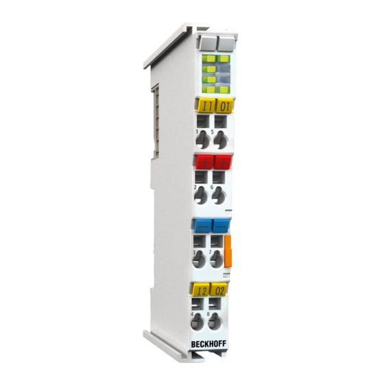
Page 48: Leds And Connection
Mounting and wiring LEDs and connection Fig. 27: EL3681 Connection Connection EL3681 Terminal point Comment Terminal point for voltage measurement (internally connected with terminal point 5) Ground (internally connected with terminal point 6) 10 A Terminal point for current measurement, 10 A range... -
Page 49: Disposal
Products marked with a crossed-out wheeled bin shall not be discarded with the normal waste stream. The device is considered as waste electrical and electronic equipment. The national regulations for the disposal of waste electrical and electronic equipment must be observed. EL3681 Version: 3.0... -
Page 50: Commissioning
• “offline”: The configuration can be customized by adding and positioning individual components. These can be selected from a directory and configured. ◦ The procedure for the offline mode can be found under http://infosys.beckhoff.com: TwinCAT 2 → TwinCAT System Manager → IO Configuration → Add an I/O device •... - Page 51 • Linked via the X001 port (RJ-45): EK1100 EtherCAT Coupler • Connected to the EK1100 EtherCAT Coupler on the right (E-bus): EL2008 (8-channel digital output terminal 24 V ; 0.5 A) • (Optional via X000: a link to an external PC for the user interface) EL3681 Version: 3.0...
- Page 52 Note that all combinations of a configuration are possible; for example, the EL1004 terminal could also be connected after the coupler, or the EL2008 terminal could additionally be connected to the CX2040 on the right, in which case the EK1100 coupler wouldn’t be necessary. Version: 3.0 EL3681...
-
Page 53: Twincat 2
In the menu under “Actions” → “Choose Target System...”, the following window is opened for this via the symbol “ ” or the “F8” key: EL3681 Version: 3.0... - Page 54 Once the target system has been entered, it is available for selection as follows (a correct password may have to be entered before this): After confirmation with “OK”, the target system can be accessed via the System Manager. Version: 3.0 EL3681...
- Page 55 Confirm the message “Find new boxes”, in order to determine the terminals connected to the devices. “Free Run” enables manipulation of input and output values in “Config Mode” and should also be acknowledged. Based on the example configuration [} 51] described at the beginning of this section, the result is as follows: EL3681 Version: 3.0...
- Page 56 TwinCAT PLC Control is the development environment for generating the controller in different program environments: TwinCAT PLC Control supports all languages described in IEC 61131-3. There are two text- based languages and three graphical languages. • Text-based languages ◦ Instruction List (IL) ◦ Structured Text (ST) Version: 3.0 EL3681...
- Page 57 The following section refers solely to Structured Text (ST). After starting TwinCAT PLC Control, the following user interface is shown for an initial project: Fig. 37: TwinCAT PLC Control after startup Example variables and an example program have been created and stored under the name “PLC_example.pro”: EL3681 Version: 3.0...
- Page 58 Manager has been notified, the warning no longer appears. First, integrate the TwinCAT PLC Control project in the System Manager. This is performed via the context menu of the PLC configuration (right-click) and selecting “Append PLC Project…”: Fig. 39: Appending the TwinCAT PLC Control project Version: 3.0 EL3681...
- Page 59 “PLC_example” and via “Modify Link...” “Standard”: Fig. 41: Creating the links between PLC variables and process objects In the window that opens, the process object for the “bEL1004_Ch4” BOOL-type variable can be selected from the PLC configuration tree: EL3681 Version: 3.0...
- Page 60 The links can also be checked by selecting “Goto Link Variable” from the context menu of a variable. The opposite linked object, in this case the PDO, is automatically selected: Version: 3.0 EL3681...
- Page 61 The PLC system can then be started as described below. Starting the controller Starting from a remote system, the PLC control has to be linked with the embedded PC over the Ethernet via “Online” → “Choose Runtime System…”: EL3681 Version: 3.0...
- Page 62 This results in the message “No program on the controller! Should the new program be loaded?”, which should be confirmed with “Yes”. The runtime environment is ready for the program start: Version: 3.0 EL3681...
-
Page 63: Twincat 3
(see “TwinCAT System Manager” of TwinCAT 2) for communication with the electromechanical components. After successful installation of the TwinCAT system on the PC to be used for development, TwinCAT 3 (shell) displays the following user interface after startup: EL3681 Version: 3.0... - Page 64 First create a new project via (or under “File”→“New”→ “Project…”). In the following dialog, make the corresponding entries as required (as shown in the diagram): Fig. 48: Create new TwinCAT 3 project The new project is then available in the project folder explorer: Version: 3.0 EL3681...
- Page 65 Via the symbol in the menu bar: expand the pull-down menu: and open the following window: Fig. 50: Selection dialog: Choose the target system EL3681 Version: 3.0...
- Page 66 The TwinCAT System Manager may first have to be set to “Config mode” via or via the menu “TwinCAT” → “Restart TwinCAT (Config Mode)”. Fig. 52: Select “Scan” Confirm the warning message, which follows, and select the “EtherCAT” devices in the dialog: Version: 3.0 EL3681...
- Page 67 A scan (search function) can also be initiated by selecting “Device ...” from the context menu, which then only reads the elements below which are present in the configuration: EL3681 Version: 3.0...
- Page 68 The following section refers solely to Structured Text (ST). In order to create a programming environment, a PLC subproject is added to the example project via the context menu of the “PLC” in the project folder explorer by selecting “Add New Item….”: Version: 3.0 EL3681...
- Page 69 Fig. 57: Specifying the name and directory for the PLC programming environment The “Main” program, which already exists due to selecting “Standard PLC project”, can be opened by double-clicking on “PLC_example_project” in “POUs”. The following user interface is shown for an initial project: EL3681 Version: 3.0...
- Page 70 Commissioning Fig. 58: Initial “Main” program for the standard PLC project Now example variables and an example program have been created for the next stage of the process: Version: 3.0 EL3681...
- Page 71 “Assignments” in the project folder explorer: Assigning variables Via the menu of an instance – variables in the “PLC” context, use the “Modify Link…” option to open a window to select a suitable process object (PDO) for linking: EL3681 Version: 3.0...
- Page 72 4 of the EL1004 terminal is selected for linking. In contrast, the checkbox “All types” must be ticked to create the link for the output variables, in order to allocate a set of eight separate output bits to a byte variable in this case. The following diagram shows the whole process: Version: 3.0 EL3681...
- Page 73 PDOs to a variable. However, in this example, it would not be possible to select all output bits for the EL2008, since the terminal only makes individual digital outputs available. If a terminal has a byte, word, EL3681 Version: 3.0...
- Page 74 5. Then the project folder must be created. This can be done either via the key combination “CTRL + Shift + B” or via the “Build” tab in TwinCAT. 6. The structure in the “PLC” tab of the terminal must then be linked to the created instance. Version: 3.0 EL3681...
- Page 75 A few seconds later, the corresponding status of the Run mode is displayed in the form of a rotating symbol at the bottom right of the VS shell development environment. The PLC system can then be started as described below. EL3681 Version: 3.0...
- Page 76 Fig. 69: TwinCAT 3 development environment (VS shell): logged-in, after program startup The two operator control elements for stopping and logout result in the required action (also, “Shift + F5” can be used for stop, or both actions can be selected via the PLC menu). Version: 3.0 EL3681...
-
Page 77: Twincat Development Environment
5.2.1 Installation of the TwinCAT real-time driver In order to assign real-time capability to a standard Ethernet port of an IPC controller, the Beckhoff real-time driver has to be installed on this port under Windows. This can be done in several ways. - Page 78 This have to be called up by the menu “TwinCAT” within the TwinCAT 3 environment: Fig. 71: Call up under VS Shell (TwinCAT 3) B: Via TcRteInstall.exe in the TwinCAT directory Fig. 72: TcRteInstall in the TwinCAT directory In both cases, the following dialog appears: Version: 3.0 EL3681...
- Page 79 TwinCAT 3: the properties of the EtherCAT device can be opened by double click on “Device .. (EtherCAT)” within the Solution Explorer under “I/O”: After the installation the driver appears activated in the Windows overview for the network interface (Windows Start → System Properties → Network) EL3681 Version: 3.0...
- Page 80 Commissioning Fig. 75: Windows properties of the network interface A correct setting of the driver could be: Fig. 76: Exemplary correct driver setting for the Ethernet port Other possible settings have to be avoided: Version: 3.0 EL3681...
- Page 81 Commissioning Fig. 77: Incorrect driver settings for the Ethernet port EL3681 Version: 3.0...
- Page 82 DHCP. In this way the delay associated with the DHCP client for the Ethernet port assigning itself a default IP address in the absence of a DHCP server is avoided. A suitable address space is 192.168.x.x, for example. Fig. 78: TCP/IP setting for the Ethernet port Version: 3.0 EL3681...
-
Page 83: Notes Regarding Esi Device Description
The files are read (once) when a new System Manager window is opened, if they have changed since the last time the System Manager window was opened. A TwinCAT installation includes the set of Beckhoff ESI files that was current at the time when the TwinCAT build was created. - Page 84 1018 in the configuration. This is also stated by the Beckhoff compatibility rule. Refer in particular to the chapter “General notes on the use of Beckhoff EtherCAT IO components” and for manual configuration to the chapter “Offline configuration creation [} 88]”.
- Page 85 Faulty ESI file If an ESI file is faulty and the System Manager is unable to read it, the System Manager brings up an information window. Fig. 84: Information window for faulty ESI file (left: TwinCAT 2; right: TwinCAT 3) EL3681 Version: 3.0...
- Page 86 Commissioning Reasons may include: • Structure of the *.xml does not correspond to the associated *.xsd file → check your schematics • Contents cannot be translated into a device description → contact the file manufacturer Version: 3.0 EL3681...
-
Page 87: Twincat Esi Updater
Commissioning 5.2.3 TwinCAT ESI Updater For TwinCAT 2.11 and higher, the System Manager can search for current Beckhoff ESI files automatically, if an online connection is available: Fig. 85: Using the ESI Updater (>= TwinCAT 2.11) The call up takes place under: “Options” → “Update EtherCAT Device Descriptions”... -
Page 88: Offline Configuration Creation
EL6601/EL6614 terminal select “EtherCAT Automation Protocol via EL6601”. Fig. 88: Selecting the EtherCAT connection (TwinCAT 2.11, TwinCAT 3) Then assign a real Ethernet port to this virtual device in the runtime system. Fig. 89: Selecting the Ethernet port Version: 3.0 EL3681... - Page 89 Fig. “Selection dialog for new EtherCAT device”. If the preceding device has several free ports (e.g. EK1122 or EK1100), the required port can be selected on the right-hand side (A). Overview of physical layer • “Ethernet”: cable-based 100BASE-TX: couplers, box modules, devices with RJ45/M8/M12 connector EL3681 Version: 3.0...
- Page 90 (i.e. highest) revision and therefore the latest state of production is displayed in the selection dialog for Beckhoff devices. To show all device revisions available in the system as ESI descriptions tick the “Show Hidden Devices” check box, see Fig. “Display of previous revisions”.
- Page 91 If current ESI descriptions are available in the TwinCAT system, the last revision offered in the selection dialog matches the Beckhoff state of production. It is recommended to use the last device revision when creating a new configuration, if current Beckhoff devices are used in the real application. Older revisions should only be used if older devices from stock are to be used in the application.
- Page 92 Commissioning Fig. 96: EtherCAT terminal in the TwinCAT tree (left: TwinCAT 2; right: TwinCAT 3) Version: 3.0 EL3681...
-
Page 93: Online Configuration Creation
This scan mode attempts to find not only EtherCAT devices (or Ethernet ports that are usable as such), but also NOVRAM, fieldbus cards, SMB etc. However, not all devices can be found automatically. Fig. 99: Note for automatic device scan (left: TwinCAT 2; right: TwinCAT 3) EL3681 Version: 3.0... - Page 94 [} 98] with the defined initial configuration.Background: since Beckhoff occasionally increases the revision version of the delivered products for product maintenance reasons, a configuration can be created by such a scan which (with an identical machine construction) is identical according to the device list;...
- Page 95 Likewise, A might create spare parts stores worldwide for the coming series-produced machines with EL2521-0025-1018 terminals. After some time Beckhoff extends the EL2521-0025 by a new feature C. Therefore the FW is changed, outwardly recognizable by a higher FW version and a new revision -1019. Nevertheless the new device naturally supports functions and interfaces of the predecessor version(s);...
- Page 96 Fig. 108: Displaying of “Free Run” and “Config Mode” toggling right below in the status bar Fig. 109: TwinCAT can also be switched to this state by using a button (left: TwinCAT 2; right: TwinCAT 3) The EtherCAT system should then be in a functional cyclic state, as shown in Fig. Online display example. Version: 3.0 EL3681...
- Page 97 The connections and devices should be checked in a targeted manner, e.g. via the emergency scan. Then re-run the scan. Fig. 111: Faulty identification In the System Manager such devices may be set up as EK0000 or unknown devices. Operation is not possible or meaningful. EL3681 Version: 3.0...
- Page 98 A “ChangeTo” or “Copy” should only be carried out with care, taking into consideration the Beckhoff IO compatibility rule (see above). The device configuration is then replaced by the revision found; this can affect the supported process data and functions.
- Page 99 If current ESI descriptions are available in the TwinCAT system, the last revision offered in the selection dialog matches the Beckhoff state of production. It is recommended to use the last device revision when creating a new configuration, if current Beckhoff devices are used in the real application. Older revisions should only be used if older devices from stock are to be used in the application.
- Page 100 - PDO (process data: Sequence, SyncUnit SU, SyncManager SM, EntryCount, Ent-ry.Datatype) This function is preferably to be used on AX5000 devices. Change to Alternative Type The TwinCAT System Manager offers a function for the exchange of a device: Change to Alternative Type Version: 3.0 EL3681...
-
Page 101: Ethercat Subscriber Configuration
Several terminals, as for instance the EL6695 provide special functions by a tab with its own terminal name, so “EL6695” in this case. A specific tab “Settings” by terminals with a wide range of setup options will be provided also (e.g. EL3751). “General” tab Fig. 119: “General” tab EL3681 Version: 3.0... - Page 102 CANopen process data objects (Process Data Objects, PDOs). The user can select a PDO via PDO assignment and modify the content of the individual PDO via this dialog, if the EtherCAT slave supports this function. Version: 3.0 EL3681...
- Page 103 For Beckhoff EtherCAT EL, ES, EM, EJ and EP slaves the following applies in general: • The input/output process data supported by the device are defined by the manufacturer in the ESI/XML description.
- Page 104 (CoE) or Servo drive over EtherCAT protocol. This tab indicates which download requests are sent to the mailbox during startup. It is also possible to add new mailbox requests to the list display. The download requests are sent to the slave in the same order as they are shown in the list. Version: 3.0 EL3681...
- Page 105 (CoE) protocol. This dialog lists the content of the object list of the slave (SDO upload) and enables the user to modify the content of an object from this list. Details for the objects of the individual EtherCAT devices can be found in the device-specific object descriptions. EL3681 Version: 3.0...
- Page 106 The Update list button updates all objects in the displayed list Auto Update If this check box is selected, the content of the objects is updated automatically. Advanced The Advanced button opens the Advanced Settings dialog. Here you can specify which objects are displayed in the list. Version: 3.0 EL3681...
- Page 107 Offline - via EDS File If this option button is selected, the list of the objects included in the object list is read from an EDS file provided by the user. “Online” tab Fig. 126: “Online” tab EL3681 Version: 3.0...
- Page 108 • DC-Synchron (Input based) • DC-Synchron Advanced Settings… Advanced settings for readjustment of the real time determinant TwinCAT-clock Detailed information to Distributed Clocks is specified on http://infosys.beckhoff.com: Fieldbus Components → EtherCAT Terminals → EtherCAT System documentation → EtherCAT basics → Distributed Clocks Version: 3.0...
- Page 109 Sync unit to which this PDO is assigned. PDO Content Indicates the content of the PDO. If flag F (fixed content) of the PDO is not set the content can be modified. EL3681 Version: 3.0...
-
Page 110: Import/Export Of Ethercat Devices With Sci And Xti
• outside, i.e. beyond the TwinCAT limits: Export/Import as sci file. An example is provided below for illustration purposes: an EL3702 terminal with standard setting is switched to 2-fold oversampling (blue) and the optional PDO "StartTimeNextLatch" is added (red): Version: 3.0 EL3681... - Page 111 The two methods for exporting and importing the modified terminal referred to above are demonstrated below. 5.2.8.2 Procedure within TwinCAT with xti files Each IO device can be exported/saved individually: The xti file can be stored: and imported again in another TwinCAT system via "Insert Existing item": EL3681 Version: 3.0...
- Page 112 • If TwinCAT is offline (i.e. if there is no connection to an actual running controller) a warning message may appear, because after executing the function the system attempts to reload the EtherCAT segment. However, in this case this is not relevant for the result and can be acknowledged by clicking Version: 3.0 EL3681...
- Page 113 Reference to the original ESI file. Export Save SCI file. • A list view is available for multiple selections (Export multiple SCI files): • Selection of the slaves to be exported: ◦ All: All slaves are selected for export. EL3681 Version: 3.0...
- Page 114 • The sci file can be saved locally: • The export takes place: Import • An sci description can be inserted manually into the TwinCAT configuration like any normal Beckhoff device description. • The sci file must be located in the TwinCAT ESI path, usually under: C:\TwinCAT\3.1\Config\Io\EtherCAT...
- Page 115 Default setting whether the configured MAC and IP addresses are exported. Keep modules Default setting whether the modules persist. Generic Reload Devices Setting whether the Reload Devices command is executed before the SCI export. This is strongly recommended to ensure a consistent slave configuration. EL3681 Version: 3.0...
- Page 116 Commissioning SCI error messages are displayed in the TwinCAT logger output window if required: Version: 3.0 EL3681...
-
Page 117: General Commissioning Instructions For An Ethercat Slave
See the corresponding device documentation The colors in Fig. Selection of the diagnostic information of an EtherCAT Slave also correspond to the variable colors in the System Manager, see Fig. Basic EtherCAT Slave Diagnosis in the PLC. EL3681 Version: 3.0... - Page 118 Fig. Basic EtherCAT Slave Diagnosis in the PLC shows an example of an implementation of basic EtherCAT Slave Diagnosis. A Beckhoff EL3102 (2-channel analogue input terminal) is used here, as it offers both the communication diagnosis typical of a slave and the functional diagnosis that is specific to a channel.
- Page 119 The CoE parameter directory (CanOpen-over-EtherCAT) is used to manage the set values for the slave concerned. Changes may, in some circumstances, have to be made here when commissioning a relatively complex EtherCAT Slave. It can be accessed through the TwinCAT System Manager, see Fig. EL3102, CoE directory: EL3681 Version: 3.0...
- Page 120 Commissioning interfaces are being introduced as part of an ongoing process for EL/EP EtherCAT devices. These are available in TwinCAT System Managers from TwinCAT 2.11R2 and above. They are integrated into the System Manager through appropriately extended ESI configuration files. Version: 3.0 EL3681...
- Page 121 The target state wanted by the user, and which is brought about automatically at start-up by TwinCAT, can be set in the System Manager. As soon as TwinCAT reaches the status RUN, the TwinCAT EtherCAT Master will approach the target states. EL3681 Version: 3.0...
- Page 122 Fig. 133: Default target state in the Slave Manual Control There are particular reasons why it may be appropriate to control the states from the application/task/PLC. For instance: • for diagnostic reasons • to induce a controlled restart of axes Version: 3.0 EL3681...
- Page 123 The pre-calculated theoretical maximum E-Bus current is displayed in the TwinCAT System Manager as a column value. A shortfall is marked by a negative total amount and an exclamation mark; a power feed terminal is to be placed before such a position. EL3681 Version: 3.0...
- Page 124 Fig. 136: Warning message for exceeding E-Bus current NOTICE Caution! Malfunction possible! The same ground potential must be used for the E-Bus supply of all EtherCAT terminals in a terminal block! Version: 3.0 EL3681...
-
Page 125: Notices On Analog Specifications
Analogous to pointing devices this is the measuring scale (see IEC 61131) or also the dynamic range. For analog I/O devices from Beckhoff, the full scale value (FSV) of the respective product (also: reference value) is selected as the largest limit of the nominal measuring range and is given a positive sign. This applies to both symmetrical and asymmetrical measuring spans. -
Page 126: Measurement Error/Measurement Deviation/Measurement Uncertainty, Output Uncertainty
The following information also applies analogously to the output end value of analog output devices. The relative measuring error as a specification value of a Beckhoff analog device is specified in % of the nominal FSV (output end value) and calculated as the quotient of the numerically largest probable deviation from the true measured value (output value) with respect to the FSV (output end value): It should be noted here that the "true measured value"... -
Page 127: Temperature Coefficient Tk [Ppm/K]
A manufacturer can alleviate this by using components of a higher quality or by software means. The temperature coefficient, when indicated, specified by Beckhoff allows the user to calculate the expected measuring error outside the basic accuracy. The basic accuracy is usually specified for 23 °C ambient temperature, in special cases also at other temperature. -
Page 128: Long-Term Use
However, as is usual for technical devices, an unlimited functional assurance (also applies to accuracy) cannot be given. Beckhoff recommends checking the usability in relation to the application target within the scope of normal system maintenance, e.g. every 12-24 months. -
Page 129: Ground Reference: Single-Ended/Differential Typification
In particular this also applies to SE, even though the term suggests that only one wire is required. • The term “electrical isolation” should be clarified in advance. Beckhoff I/O devices feature 1 to 8 or more analog channels; with regard to the channel connection a distinction is made in terms of: ◦... - Page 130 The property of electrical isolation indicates whether the channels are directly connected to each other. ◦ Beckhoff I/O devices always feature electrical isolation between the field/analog side and the bus/ EtherCAT side. In other words, if two analog I/O devices are not connected via the power contacts (cable), they are effectively electrically isolated.
- Page 131 +signal can be connected to +supply or –signal to –supply. - Yes: then you can connect accordingly to a Beckhoff ‘single-ended’ input. - No: the Beckhoff ‘differential’ input for +Signal and –Signal is to be selected; +Supply and – Supply are to be connected via additional cables.
- Page 132 Commissioning Fig. 140: Connection of externally supplied sensors Classification of Beckhoff Terminals/ Box modules - Beckhoff 0/4-20 mA Terminals/ Box modules (and related product groups) are available as differential and single-ended: Single-ended Differential EL3x4x: 0-20 mA, EL3x5x: 4-20 mA, same as KL and related EL3x1x: 0-20 mA, EL3x2x: 4-20 mA, same as KL and related...
- Page 133 Commissioning Fig. 141: 2-, 3- and 4-wire connection at single-ended and differential inputs EL3681 Version: 3.0...
-
Page 134: Common-Mode Voltage And Reference Ground (Based On Differential Inputs)
Reference ground samples for Beckhoff IO devices: 1. Internal AGND fed out: EL3102/EL3112, resistive connection between the channels 2. 0 V power contact: EL3104/EL3114, resistive connection between the channels and AGND; AGND connected to 0 V power contact with low-resistance... -
Page 135: Dielectric Strength
Fig. 143: Recommended operating voltage range The device documentation may contain particular specifications and timings, taking into account: • Self-heating • Rated voltage • Insulating strength • Edge steepness of the applied voltage or holding periods • Normative environment (e.g. PELV) EL3681 Version: 3.0... -
Page 136: Temporal Aspects Of Analog/Digital Or Digital/Analog Conversion
This is the “external” view of the “Beckhoff AI channel” system – internally the signal delay in particular is composed of different components: hardware, amplifier, conversion itself, data transport and processing. - Page 137 The signal delay [ms, µs] is then the time interval between the applied electrical signal of a certain amplitude and the moment when the analog process value reaches the same value. For this purpose, the test frequency must be selected in a reasonable range; this can be, for example, 1/20 of the maximum sampling rate. EL3681 Version: 3.0...
- Page 138 3. Additional information Additional information may be provided in the specification, e.g. • actual sampling rate of the ADC (if different from the channel sampling rate) • time correction values for runtimes with different filter settings • etc. Version: 3.0 EL3681...
-
Page 139: Explanation Of The Term Gnd/Ground
– one of these points is then called the reference potential. In the Beckhoff I/O area and in particular with the analog products, various reference potentials are used and named. These are defined, named and explained here. - Page 140 Electrical restrictions according to the device documentation must be observed, e.g. common mode limits. ◦ AGND is usually a currentless reference potential. The action of interference on AGND must be avoided. ◦ Example: AGND is fed out on the device plug: Version: 3.0 EL3681...
-
Page 141: Sampling Type: Simultaneous Vs. Multiplexed
Note: The terms "simultaneous" and "multiplex" have been used for a long time and in many contexts, so they have different meanings depending on the historical background and the subject area. In this chapter and in relation to I/O, the terms are used as Beckhoff understands them as an I/O manufacturer for the benefit of the user: •... - Page 142 4 input channels to the ADC quickly one after the other in the µs range. The switching process is performed by the device itself and is usually not accessible from the outside. Fig. 149: Schematic representation of multiplex sampling with an ADC converter Version: 3.0 EL3681...
- Page 143 For analog outputs the same explanations apply, they can also be equipped with multiple simultaneous DACs or output a multiplexed DAC to several outputs. EL3681 Version: 3.0...
-
Page 144: Basic Function Principles/Functional Description
Sync Manager: 2, PDO assignment, then press the Reload button or F4 to accept the setting). Otherwise the CoE entries are write-protected. Selecting the measuring range via CoE or the process data has the same effect; "Mode" (index 0x8000:0D [} 155]) selects the measurement type, "Range" (index 0x8000:11 [} 155]) selects the measuring range: Version: 3.0 EL3681... -
Page 145: Autorange
Several measurement readings are consolidated and issued as process data approx. every 500 ms, if the filter is activated. If the filter is deactivated the EL3681 supplies approx. 16 measurement readings per second. -
Page 146: Presentation
The terminal features manufacturer and user calibration options, which can be switched on and off independently. The calibration always applies to all measuring ranges. Adaptation in 60 Hz mode and compensation of the AC system offset cannot be switched off. Version: 3.0 EL3681... -
Page 147: Process Data
5.6.1 Process image The default process image of the EL3681 has 3 inputs (Status, Settings and Value) and one output (Control). Status/Settings carry special information in the individual bits. From TwinCAT 2.11 these bits are explicitly accessible in the System Manager (see Fig. Default process image EL3681), although the complete status word (or Settings and Control) can be linked with corresponding PLC variables. - Page 148 Commissioning Fig. 151: PDO option, TwinCAT System Manager Version: 3.0 EL3681...
-
Page 149: Control, Status, Settings-Word
The settings word (SB) is stored in input process image and is transferred from the terminal to the controller. SB.15 SB.14 SB.13 SB.12 SB.11 SB.10 SB.9 SB.8 SB.7 SB.6 SB.5 SB.4 SB.3 SB.2 SB.1 SB.0 Name Current Range Current mode For explanation see entries in Object overview, index 0x6001 [} 158] EL3681 Version: 3.0... -
Page 150: Pdo Assignment
Status__Calibration in progress Index 0x1800:07 - Status__TxPDO State Index 0x1800:09 - Status__TxPDO Toggle Index 0x6000:11 [} 158] - Value 0x1A01 - SAI Range Index 0x6001:05 [} 158] - Settings__Mode Index 0x6001:09 [} 158] - Settings__Range Table 1: PDO assignment of the SyncManager Version: 3.0 EL3681... -
Page 151: Calculation Of Process Data
The scaling includes the powers of ten selected in the range. All gain factors should therefore correspond to 1/8 in order to obtain a total factor of 1. The value 8192 (0x2000) results in a total factor of 1. EL3681 Version: 3.0... - Page 152 User gain 0x8002 [} 155] (even subindices) Measured value after AC system offset 0x800F:1F AC system offset [} 157] Measured value after End value in 1 bit per 1µV / Scale Scal scaling 1µA Table 2: Legend for table 1 Version: 3.0 EL3681...
-
Page 153: Determining (User) Gain Values
0x2000. For gain G = 1 the following applies: For other values G must be replaced with the required gain factor. Before the compensation the value display option should be set to "Right-aligned": CoE index 0x8000:1D [} 155] (presentation = 1). EL3681 Version: 3.0... -
Page 154: Object Description And Parameterization
EtherCAT XML Device Description The display matches that of the CoE objects from the EtherCAT XML Device Description. We recommend downloading the latest XML file from the download area of the Beckhoff website and installing it according to installation instructions. -
Page 155: Restore Object
User calibration is switched on and off for all measuring ranges via index 0x8000:02 [} 155] "Enable user calibration". The default values are 0x0000 for offset and 0x2000 for gain (see Calibration section). The default settings can be restored via the entry 0x1011 [} 155] "Restore default parameters". EL3681 Version: 3.0... - Page 156 100 mA AC gain UINT16 0x2000 (8192 8002:19 1 A AC offset 1 A AC offset INT16 0x0000 (0 8002:1A 1 A AC gain 1 A AC gain UINT16 0x2000 (8192 8002:1B 10 A AC offset 10 A AC offset INT16 0x0000 (0 8002:1C 10 A AC gain 10 A AC gain UINT16 0x2000 (8192 Version: 3.0 EL3681...
-
Page 157: Configuration Data (Vendor-Specific)
10 A DC offset INT16 0x0000 (0 800F:16 10 A DC gain 10 A DC gain UINT16 0x2000 (8192 800F:17 100 mA AC offset 100 mA AC offset INT16 0x0000 (0 800F:18 100 mA AC gain 100 mA AC gain UINT16 0x2000 (8192 800F:19 1 A AC offset 1 A AC offset INT16 0x0000 (0 EL3681 Version: 3.0... -
Page 158: Input Data
Data type Flags Default 6001:0 SAI Range Maximum subindex UINT8 0x09 (9 6001:05 Mode Contains the selected measurement mode (e.g. DC BIT4 0x00 (0 voltage) 6001:09 Range Contains the selected measuring range (e.g. 10^2) INT8 0x00 (0 Version: 3.0 EL3681... -
Page 159: Output Data
CoE profile used (5001). The Hi-Word (23597961 contains the module profile according to the modular device profile. Index 1008 Device name Index (hex) Name Meaning Data type Flags Default 1008:0 Device name Device name of the EtherCAT slave STRING EL3681 EL3681 Version: 3.0... - Page 160 0x05 (Mode)) 1600:04 SubIndex 004 4. PDO Mapping entry (object 0x7000 (SAI Range), UINT32 0x7000:05, 4 entry 0x09 (Range)) 1600:05 SubIndex 005 5. PDO Mapping entry (object 0x7000 (SAI Range), UINT32 0x7000:09, 8 entry 0x09 (Range)) Version: 3.0 EL3681...
- Page 161 0x02 (2 1C13:01 Subindex 001 1. allocated TxPDO (contains the index of the UINT16 0x1A00 associated TxPDO mapping object) (6656 1C13:02 Subindex 002 2. allocated TxPDO (contains the index of the UINT16 0x1A01 associated TxPDO mapping object) (6657 EL3681 Version: 3.0...
- Page 162 Shift too short counter Number of occasions that the interval between SYNC0 UINT16 0x0000 (0 and SYNC1 event was too short (DC mode only) 1C32:20 Sync error The synchronization was not correct in the last cycle BOOLEAN 0x00 (0 (outputs were output too late; DC mode only) Version: 3.0 EL3681...
- Page 163 1C33:0B SM event missed as 0x1C32:11 UINT16 0x0000 (0 counter 1C33:0C Cycle exceeded as 0x1C32:12 UINT16 0x0000 (0 counter 1C33:0D Shift too short counter as 0x1C32:13 UINT16 0x0000 (0 1C33:20 Sync error as 0x1C32:32 BOOLEAN 0x00 (0 EL3681 Version: 3.0...
-
Page 164: Sample Program
We reserve the right to modify the content of this document at any time and accept no responsibility for errors and missing information. Download (https://infosys.beckhoff.com/content/1033/el3681/Resources/2086769675/.zip) All terminal settings including the CoE entries can be set via the visualization (Fig. Visualization sample program): Fig. 153: Visualization sample program... - Page 165 I/O devices, Device (EtherCAT); then on the “Adapter” tab choose “Search...”, select the appropriate adapter and confirm (see Fig. Searching the Ethernet adapter + Selection and confirmation of the Ethernet adapter). Fig. 154: Searching the Ethernet adapter Fig. 155: Selection and confirmation of the Ethernet adapter EL3681 Version: 3.0...
- Page 166 • Confirm new variable mapping, restart in RUN mode (Fig. Generate variable mapping + Restarting TwinCAT in RUN mode) Fig. 158: Generating variable mapping Fig. 159: Restarting TwinCAT in RUN mode • In TwinCAT PLC, under the “Project” menu, select “Rebuild all” to compile the project (Fig. Compile project) Version: 3.0 EL3681...
- Page 167 Commissioning Fig. 160: Compile project • In TwinCAT PLC: log in with the “F11” button, confirm loading the program (Fig. Confirming program start), run the program with the “F5” button Fig. 161: Confirming program start EL3681 Version: 3.0...
-
Page 168: Error Handling And Diagnostics
Autorange perhaps select option "scaled" or activate SAI Range (outputs). Data invalid Wait (read ADC Zero, startup or conversion error) Conversion Switch on again error after power-up **) Error LED is lit, see LED description [} 48] Version: 3.0 EL3681... -
Page 169: Appendix
Accessories Fuse Spare fuses are available as accessories. The upper of the two built-in fuses in the EL3681 is designated as a spare fuse. The fuse can be removed with pliers by pulling it upwards from its sockets (Fig. Replacing the fuse). -
Page 170: Ethercat Al Status Codes
Appendix EtherCAT AL Status Codes For detailed information please refer to the EtherCAT system description. Version: 3.0 EL3681... -
Page 171: Firmware Compatibility
Note • It is recommended to use the newest possible firmware for the respective hardware. • Beckhoff is not under any obligation to provide customers with free firmware updates for delivered products. NOTICE Risk of damage to the device! Pay attention to the instructions for firmware updates on the separate page [} 172]. -
Page 172: Firmware Update El/Es/Em/Elm/Ep/Epp/Erpxxxx
NOTICE Only use TwinCAT 3 software! A firmware update of Beckhoff IO devices must only be performed with a TwinCAT 3 installation. It is recommended to build as up-to-date as possible, available for free download on the Beckhoff website. To update the firmware, TwinCAT can be operated in the so-called FreeRun mode, a paid license is not required. -
Page 173: Device Description Esi File/Xml
(in this case EL3204). Normally the configured revision must be the same or lower than that actually present in the terminal network. For further information on this, please refer to the EtherCAT system documentation. EL3681 Version: 3.0... - Page 174 The device revision is closely linked to the firmware and hardware used. Incompatible combinations lead to malfunctions or even final shutdown of the device. Corresponding updates should only be carried out in consultation with Beckhoff support. Display of ESI slave identifier...
- Page 175 • Right-clicking on the slave in the online display opens the EEPROM Update dialog, Fig. EEPROM Update Fig. 167: EEPROM Update The new ESI description is selected in the following dialog, see Fig. Selecting the new ESI. The checkbox Show Hidden Devices also displays older, normally hidden versions of a slave. EL3681 Version: 3.0...
-
Page 176: Firmware Explanation
• offline: The EtherCAT Slave Information ESI/XML may contain the default content of the CoE. This CoE directory can only be displayed if it is included in the ESI (e.g. “Beckhoff EL5xxx.xml”). The Advanced button must be used for switching between the two views. -
Page 177: Updating Controller Firmware *.Efw
The Online CoE directory is managed by the controller and stored in a dedicated EEPROM, which is generally not changed during a firmware update. Switch to the Online tab to update the controller firmware of a slave, see Fig. Firmware Update. EL3681 Version: 3.0... - Page 178 Appendix Fig. 170: Firmware Update Proceed as follows, unless instructed otherwise by Beckhoff support. Valid for TwinCAT 2 and 3 as EtherCAT master. • Switch TwinCAT system to ConfigMode/FreeRun with cycle time >= 1 ms (default in ConfigMode is 4 ms). A FW-Update during real time operation is not recommended.
-
Page 179: Fpga Firmware *.Rbf
The TwinCAT System Manager indicates the FPGA firmware version. Click on the Ethernet card of your EtherCAT strand (Device 2 in the example) and select the Online tab. The Reg:0002 column indicates the firmware version of the individual EtherCAT devices in hexadecimal and decimal representation. EL3681 Version: 3.0... - Page 180 Fig. 172: Context menu Properties The Advanced Settings dialog appears where the columns to be displayed can be selected. Under Diagnosis/Online View select the '0002 ETxxxx Build' check box in order to activate the FPGA firmware version display. Version: 3.0 EL3681...
- Page 181 Older firmware versions can only be updated by the manufacturer! Updating an EtherCAT device The following sequence order have to be met if no other specifications are given (e.g. by the Beckhoff support): • Switch TwinCAT system to ConfigMode/FreeRun with cycle time >= 1 ms (default in ConfigMode is 4 ms).
- Page 182 • In the TwinCAT System Manager select the terminal for which the FPGA firmware is to be updated (in the example: Terminal 5: EL5001) and click the Advanced Settings button in the EtherCAT tab: • The Advanced Settings dialog appears. Under ESC Access/E²PROM/FPGA click on Write FPGA button: Version: 3.0 EL3681...
-
Page 183: Simultaneous Updating Of Several Ethercat Devices
The firmware and ESI descriptions of several devices can be updated simultaneously, provided the devices have the same firmware file/ESI. Fig. 174: Multiple selection and firmware update Select the required slaves and carry out the firmware update in BOOTSTRAP mode as described above. EL3681 Version: 3.0... -
Page 184: Restoring The Delivery State
• This reset procedure can also be adopted as the first entry in the startup list of the slave, e.g. in the state transition PREOP->SAFEOP or, as in Fig. CoE reset as a startup entry, in SAFEOP->OP. All backup objects are reset to the delivery state. Version: 3.0 EL3681... - Page 185 Alternative restore value In some older terminals (FW creation approx. before 2007) the backup objects can be switched with an alternative restore value: Decimal value: 1819238756, Hexadecimal value: 0x6C6F6164. An incorrect entry for the restore value has no effect. EL3681 Version: 3.0...
-
Page 186: Support And Service
Please contact your Beckhoff branch office or representative for local support and service on Beckhoff products! The addresses of Beckhoff's branch offices and representatives round the world can be found on her internet pages: www.beckhoff.com You will also find further documentation for Beckhoff components there. - Page 188 More Information: www.beckhoff.com/EL3681 Beckhoff Automation GmbH & Co. KG Hülshorstweg 20 33415 Verl Germany Phone: +49 5246 9630 info@beckhoff.com www.beckhoff.com...
Need help?
Do you have a question about the EL3681 and is the answer not in the manual?
Questions and answers