Sign In
Upload
Manuals
Brands
Beckhoff Manuals
Measuring Instruments
EPP3504-0023
Beckhoff EPP3504-0023 Manuals
Manuals and User Guides for Beckhoff EPP3504-0023. We have
2
Beckhoff EPP3504-0023 manuals available for free PDF download: Manual, Short Manual
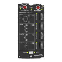
Beckhoff EPP3504-0023 Manual (256 pages)
4-Channel measuring bridge,(SG) full/half/quarter bridge, 24 bit, 10 ksps
Brand:
Beckhoff
| Category:
Network Hardware
| Size: 12.02 MB
Table of Contents
Table of Contents
4
2 Foreword
7
Notes on the Documentation
7
Safety Instructions
8
Documentation Issue Status
9
Guide through Documentation
10
Version Identification of Ethercat Devices
11
General Notes on Marking
11
Beckhoff Identification Code (BIC)
11
Fig. 1 BIC as Data Matrix Code (DMC, Code Scheme ECC200)
12
Electronic Access to the BIC (Ebic)
13
Fig. 2 Example DMC 1P072222Sbtnk4P562D71Kel1809 Q1 51S678294
13
3 Product Group: Ethercat P Box Modules
16
4 Product Overview
17
EPP3504-0023/ ERP3504-0022 - Introduction
17
Fig. 3 EPP3504-0023
17
Fig. 4 ERP3504-0022
18
EPP3504-0023/ ERP3504-0022 - Technical Data
19
EPP3504-0023/ ERP3504-0022 Overview Measurement Ranges
21
Fig. 5 Overview Measurement Ranges, Bipolar
22
Fig. 6 Overview Measurement Ranges, Unipolar
22
Measurement ±10 V
23
Fig. 7 Representation ±10 V Measurement Range
24
Measurement ±80 MV
25
Fig. 8 Representation ±80 MV Measurement Range
26
Rtd/Pt1000 Measurement
27
Fig. 9 Chart: RTD Measuring Range
30
Fig. 10 Concatenation of the Uncertainties in RTD Measurement
30
Fig. 11 Diagram for Basic Accuracy for Pt1000, 3-Wire Connection
31
Fig. 12 Diagram for Basic Accuracy for Pt1000, 4-Wire Connection
31
Fig. 13 Diagram Noise Enoise, Ptp in Dependence on Sensor Temperature
33
Potentiometer Measurement
34
Fig. 14 Representation Potentiometer Measurement Range
35
Measurement SG 1/1 Bridge (Full Bridge) 4/6-Wire Connection
36
Measurement SG 1/2 Bridge (Half Bridge) 3/5-Wire Connection
40
Measurement SG 1/4 Bridge (Quarter-Bridge) 2/3-Wire Connection
44
Fig. 15 Connection of the Quarter Bridge
45
Fig. 16 Relationship between Ubridge/Uexc and ∆R1
46
Process Data Interpretation
53
Fig. 17 Basic Range of a Process Data Value
53
General Information on Measuring Accuracy/Measurement Uncertainty
54
Scope of Supply
59
5 Commissioning
60
Notes to Short Documentation
60
Coe Overview
61
General Access to Online Coe Values
61
Fig. 18 Example: Double Click the Coe Object PAI-Settings, Index Interface of Channel 1 of an Elm3Xxx Terminal
61
Fig. 19 Function Blocks (Fbs) for Coe Access to the Twincat Tc2_Ethercat.lib
62
Fig. 20 Twincat Filtercontrol Embedded in the Configuration Dialog of an Epp35Xx/ Erp35Xx Box Module
62
Fig. 21 Filter Coefficients Nos. 1 to 12 of Channel 1 in the Coe Online of an ELM3602 Ethercat Ter- Minal
63
Fig. 22 Startup List of an ELM3602 Ethercat Terminal, Already Partially Modified by Direct Input
63
Fig. 23 Calling the ADS Monitor Command Test
64
Fig. 24 Activation of "Ethercat Addr
64
0X10E2 Manufacturer-Specific Identification Code
66
0X10F3 Diagnosis History
66
0X60N0 PAI Status Ch.[N+1]
66
0X60N1 PAI Samples Ch.[N+1] (24 Bit)
67
0X60N2 PAI Samples Ch.[N+1] (16 Bit)
67
0X60N3 PAI Samples Ch.[N+1] (REAL32)
67
0X60N5 PAI Timestamp Ch.[N+1]
67
0X60N6 PAI Synchronous Oversampling Ch.[N+1]
68
0X70N0 PAI Control Ch.[N+1]
68
0X80N0 PAI Settings Ch.[N+1]
68
0X80N1 PAI Filter 1 Settings Ch.[N+1]
71
0X80N3 PAI Filter 2 Settings Ch.[N+1]
71
0X80N6 PAI Scaler Settings Ch.[N+1]
71
0X80Na PAI Extended Settings Ch.[N+1]
72
0X80Ne PAI User Calibration Ch.[N+1]
72
0X80Nf PAI Vendor Calibration Data Ch.[N+1]
73
0X90N0 PAI Internal Data Ch.[N+1]
74
0X90N2 PAI Info Data Ch.[N+1]
74
0X90Nf PAI Calibration Dates Ch.[N+1]
76
0Xf000 Modular Device Profile
81
0Xf008 Code Word
81
0Xf009 Password Protection
81
0Xf010 Module List
81
0Xf083 BTN
82
0Xf900 PAI Info Data
82
0Xf912 Filter Info
82
0Xfb00 PAI Command
83
0X80N0:01 PAI Settings.interface
84
Sample Programs
85
Fig. 25 Opening the *. Tnzip Archive
85
Fig. 26 Search of the Existing HW Configuration for the Ethercat Configuration of the Example
85
Sample Program 1 and 2 (Offset/Gain)
86
Sample Program 3 (Write Lookup Table)
92
Sample Program 4 (Generate Lookup Table)
94
Sample Program 5 (Write Filter Coefficients)
95
Sample Program 6 (Interlacing of Measured Values)
98
Fig. 27 Process of Interlacing the Input Data
98
Fig. 28 Configuration and Setup for Sample Program 6: Doubling of the Sample Rate with 2 X EL3751
99
Fig. 29 Setting the DC Shift Time for Terminal 2
99
Fig. 30 Oversampling 20 Ksps with 2 X EL3751 with Input Signals (Below) and Result Signal (Top)
101
Fig. 31 Oversampling 20 Ksps with 2 X EL3751 Shows Input Value 1 and Input Value 2 Alternately for a Result Value
101
Sample Program 7 (General Decimation in the PLC)
102
Fig. 32 Decimation from 20 Μs (Left) to 22.675
105
Sample Program 8 (Diagnosis Messages)
107
Sample Program 9 (Measuring Range Combination)
108
Fig. 33 Principle of Combining Two Measuring Channels with FSV1 and FSV2
109
Fig. 34 Possible Structure for the "Measurement Range Combination" Sample Program
110
Fig. 35 Combination of Two Channels of the ELM3602-0002 with ±5 V and ±80 MV Measuring Range
111
Sample Program 10 (FB for Real Time Diagnosis)
112
Fig. 36 Combination of Two Channels of the ELM3602-0002: Supply of a Delta Voltage in the Positive Transition Range
112
Fig. 37 Function Block as an Example for Analysis of Diagnostics Information of the Box Module
113
Fig. 38 Creation of PDO Variables (Twincat Version >= V3.1.4024.0)
114
Fig. 39 Creation of the Smpdovariables (Twincat Version >= V3.1.4022.30)
114
Sample Program 11 (Scripts for Generation and Transformation of Filter Coefficients)
115
Sample Program 12 (R/W Signature of Calibration)
115
Fig. 40 Seek the Generated Data Type of Smpdovariables
115
Fig. 41 Visualization of the Sample Implementation: Calibration Signature
116
Sample Program 13: Reading the BIC from the Coe
117
6 Features
119
7 Commissioning on Ethercat Master
120
General Commissioning Instructions for an Ethercat Slave
120
Twincat Quick Start
128
Twincat 2
130
Twincat 3
140
Twincat Development Environment
154
Installation of the Twincat Real-Time Driver
154
Notes Regarding ESI Device Description
160
Twincat ESI Updater
164
Distinction between Online and Offline
164
OFFLINE Configuration Creation
165
ONLINE Configuration Creation
170
Ethercat Subscriber Configuration
178
Import/Export of Ethercat Devices with SCI and XTI
187
Ethercat Basics
194
Ethercat Cabling - Wire-Bound
195
General Notes for Setting the Watchdog
197
Ethercat State Machine
199
Coe Interface
200
Distributed Clock
205
8 Mounting and Wiring
206
Mounting
206
Dimensions
206
Fixing
207
Functional Earth (FE)
208
Tightening Torques for Plug Connectors
209
Notes Regarding Connectors and Wiring
210
Note - Power Supply
212
Notes on Connection Technology EPP3504-0023
213
Connectors
214
Accessories
215
Power Supply, Potential Groups
216
Status Leds
218
RUN, Channel 1
218
Supply Voltage
219
Ethercat
219
Conductor Losses
220
Disposal
221
9 Appendix
222
Diagnostics - Basic Principles of Diag Messages
222
Tceventlogger and IO
229
Ethercat al Status Codes
233
Firmware Update El/Es/Em/Elm/Ep/Epp/Erpxxxx
233
Device Description ESI File/Xml
235
Firmware Explanation
238
Updating Controller Firmware *.Efw
238
FPGA Firmware *.Rbf
240
Simultaneous Updating of Several Ethercat Devices
244
Firmware Compatibility
245
Restoring the Delivery State
246
Notes on Operation
247
Continuative Documentation for I/O Components with Analog in and Outputs
248
Support and Service
249
Reshipment and Return
249
List of Illustrations
250
Advertisement
Beckhoff EPP3504-0023 Short Manual (253 pages)
4-channel measuring bridge,(SG) full/half/quarter bridge, 24 bit, 10 ksps
Brand:
Beckhoff
| Category:
Measuring Instruments
| Size: 11.48 MB
Table of Contents
Table of Contents
3
Foreword
7
Notes on the Documentation
7
Safety Instructions
8
Documentation Issue Status
9
Version Identification of Ethercat Devices
9
General Notes on Marking
9
Beckhoff Identification Code (BIC)
10
Fig. 1 BIC as Data Matrix Code (DMC, Code Scheme ECC200)
10
Fig. 2 Example DMC 1P072222Sbtnk4P562D71Kel1809 Q1 51S678294
11
Electronic Access to the BIC (Ebic)
12
Product Group: Ethercat P Box Modules
14
Product Overview
15
EPP3504-0023 - Introduction
15
Fig. 3 EPP3504-0023
15
EPP3504-0023 - Technical Data
16
EPP3504-0023 Overview Measurement Ranges
18
Fig. 4 Overview Measurement Ranges, Bipolar
19
Fig. 5 Overview Measurement Ranges, Unipolar
19
Measurement ±10 V
20
Fig. 6 Representation ±10 V Measurement Range
21
Measurement ±80 MV
22
Fig. 7 Representation ±80 MV Measurement Range
23
Rtd/Pt1000 Measurement
24
Fig. 8 Chart: RTD Measuring Range
27
Fig. 9 Concatenation of the Uncertainties in RTD Measurement
27
Fig. 10 Diagram for Basic Accuracy for Pt1000, 3-Wire Connection
28
Fig. 11 Diagram for Basic Accuracy for Pt1000, 4-Wire Connection
28
Fig. 12 Diagram Noise Enoise, Ptp in Dependence on Sensor Temperature
30
Potentiometer Measurement
31
Fig. 13 Representation Potentiometer Measurement Range
32
Measurement SG 1/1 Bridge (Full Bridge) 4/6-Wire Connection
33
Measurement SG 1/2 Bridge (Half Bridge) 3/5-Wire Connection
38
Measurement SG 1/4 Bridge (Quarter-Bridge) 2/3-Wire Connection
43
Fig. 14 Connection of the Quarter Bridge
44
Fig. 15 Relationship between Ubridge/Uexc and ∆R1
45
Process Data Interpretation
52
Fig. 16 Basic Range of a Process Data Value
52
General Information on Measuring Accuracy/Measurement Uncertainty
53
Scope of Supply
58
Notes to Short Documentation
59
Commissioning
59
Fig. 17 Example: Double Click the Coe Object PAI-Settings, Index Interface of Channel 1 of an Elm3Xxx Terminal
60
Coe Overview
60
General Access to Online Coe Values
60
Fig. 18 Function Blocks (Fbs) for Coe Access to the Twincat Tc2_Ethercat.lib
61
Fig. 19 Twincat Filtercontrol Embedded in the Configuration Dialog of an Epp35Xx Box Module
61
Fig. 20 Filter Coefficients Nos. 1 to 12 of Channel 1 in the Coe Online of an ELM3602 Ethercat Ter- Minal
62
Fig. 21 Startup List of an ELM3602 Ethercat Terminal, Already Partially Modified by Direct Input
62
Fig. 22 Calling the ADS Monitor Command Test
63
Fig. 23 Activation of "Ethercat Addr
63
0X60N0 PAI Status Ch.[N+1]
65
0X10F3 Diagnosis History
65
0X10E2 Manufacturer-Specific Identification Code
65
0X60N1 PAI Samples Ch.[N+1] (24 Bit)
66
0X60N2 PAI Samples Ch.[N+1] (16 Bit)
66
0X60N3 PAI Samples Ch.[N+1] (REAL32)
66
0X60N5 PAI Timestamp Ch.[N+1]
66
0X60N6 PAI Synchronous Oversampling Ch.[N+1]
67
0X70N0 PAI Control Ch.[N+1]
67
0X80N0 PAI Settings Ch.[N+1]
67
0X80N6 PAI Scaler Settings Ch.[N+1]
70
0X80N1 PAI Filter 1 Settings Ch.[N+1]
70
0X80N3 PAI Filter 2 Settings Ch.[N+1]
70
0X80Na PAI Extended Settings Ch.[N+1]
71
0X80Ne PAI User Calibration Ch.[N+1]
71
0X80Nf PAI Vendor Calibration Data Ch.[N+1]
72
0X90N0 PAI Internal Data Ch.[N+1]
73
0X90N2 PAI Info Data Ch.[N+1]
73
0X90Nf PAI Calibration Dates Ch.[N+1]
75
0Xf009 Password Protection
80
0Xf008 Code Word
80
0Xf000 Modular Device Profile
80
0Xf010 Module List
81
0Xf083 BTN
81
0Xf900 PAI Info Data
81
0Xf912 Filter Info
81
0Xfb00 PAI Command
82
0X80N0:01 PAI Settings.interface
83
Sample Programs
84
Fig. 24 Opening the *. Tnzip Archive
84
Fig. 25 Search of the Existing HW Configuration for the Ethercat Configuration of the Example
84
Sample Program 1 and 2 (Offset/Gain)
85
Sample Program 3 (Write Lookup Table)
91
Sample Program 4 (Generate Lookup Table)
93
Sample Program 5 (Write Filter Coefficients)
94
Sample Program 6 (Interlacing of Measured Values)
97
Fig. 26 Process of Interlacing the Input Data
97
Fig. 27 Configuration and Setup for Sample Program 6: Doubling of the Sample Rate with 2 X EL3751
98
Fig. 28 Setting the DC Shift Time for Terminal 2
98
Fig. 29 Oversampling 20 Ksps with 2 X EL3751 with Input Signals (Below) and Result Signal (Top)
100
Fig. 30 Oversampling 20 Ksps with 2 X EL3751 Shows Input Value 1 and Input Value 2 Alternately for a Result Value
100
Sample Program 7 (General Decimation in the PLC)
101
Fig. 31 Decimation from 20 Μs (Left) to 22.675
104
Sample Program 8 (Diagnosis Messages)
106
Sample Program 9 (Measuring Range Combination)
107
Fig. 32 Principle of Combining Two Measuring Channels with FSV1 and FSV2
108
Fig. 33 Possible Structure for the "Measurement Range Combination" Sample Program
109
Fig. 34 Combination of Two Channels of the ELM3602-0002 with ±5 V and ±80 MV Measuring Range
110
Sample Program 10 (FB for Real Time Diagnosis)
111
Fig. 35 Combination of Two Channels of the ELM3602-0002: Supply of a Delta Voltage in the Positive Transition Range
111
Fig. 36 Function Block as an Example for Analysis of Diagnostics Information of the Box Module
112
Fig. 38 Creation of the Smpdovariables (Twincat Version >= V3.1.4022.30)
113
Fig. 37 Creation of PDO Variables (Twincat Version >= V3.1.4024.0)
113
Sample Program 11 (Scripts for Generation and Transformation of Filter Coefficients)
114
Sample Program 12 (R/W Signature of Calibration)
114
Fig. 39 Seek the Generated Data Type of Smpdovariables
114
Fig. 40 Visualization of the Sample Implementation: Calibration Signature
115
Sample Program 13: Reading the BIC from the Coe
116
Fig. 41 Test Data to Illustrate the Content of Patmanfactspecidcode[0]^ of the FB
117
Features
118
Commissioning on Ethercat Master
119
General Commissioning Instructions for an Ethercat Slave
119
Twincat Quick Start
127
Twincat 2
129
Twincat 3
139
Twincat Development Environment
152
Installation of the Twincat Real-Time Driver
153
Notes Regarding ESI Device Description
159
Twincat ESI Updater
163
Distinction between Online and Offline
163
OFFLINE Configuration Creation
164
ONLINE Configuration Creation
169
Ethercat Subscriber Configuration
177
Import/Export of Ethercat Devices with SCI and XTI
186
Ethercat Basics
192
Ethercat Cabling - Wire-Bound
192
General Notes for Setting the Watchdog
193
Ethercat State Machine
195
Coe Interface
197
Distributed Clock
202
Mounting and Wiring
203
Mounting
203
Dimensions
203
Fixing
204
Functional Earth (FE)
205
Tightening Torques for Plug Connectors
206
Notes Regarding Connectors and Wiring
207
Note - Power Supply
209
Notes on Connection Technology EPP3504-0023
210
Connectors
211
Accessories
212
Power Supply, Potential Groups
213
Status Leds
215
RUN, Channel 1
215
Supply Voltage
216
Ethercat
216
Conductor Losses
217
Disposal
218
Appendix
219
Diagnostics - Basic Principles of Diag Messages
219
Tceventlogger and IO
226
Ethercat al Status Codes
230
Firmware Update El/Es/Em/Elm/Epxxxx
230
Device Description ESI File/Xml
232
Firmware Explanation
235
Updating Controller Firmware *.Efw
235
FPGA Firmware *.Rbf
237
Simultaneous Updating of Several Ethercat Devices
241
Firmware Compatibility
242
Restoring the Delivery State
243
Notes on Operation
244
Continuative Documentation for I/O Components with Analog in and Outputs
245
Support and Service
246
Reshipment and Return
246
List of Illustrations
247
Advertisement
Related Products
Beckhoff EL3692
Beckhoff EP3744-0041
Beckhoff EP3744-1041
Beckhoff EJ3255
Beckhoff EPP3752-0000
Beckhoff EP6070-0060
Beckhoff EL3681
Beckhoff EP3751-0160
Beckhoff EPP3174
Beckhoff EPP3184
Beckhoff Categories
Touch terminals
Industrial PC
Control Unit
Touch Panel
Power Supply
More Beckhoff Manuals
Login
Sign In
OR
Sign in with Facebook
Sign in with Google
Upload manual
Upload from disk
Upload from URL