
Related Manuals for Beckhoff EP3356-0022


Summary of Contents for Beckhoff EP3356-0022
- Page 1 Documentation | EN EP3356-0022 1-channel precise load cell analysis (resistor bridge), 24 bit 2020-09-22 | Version: 1.4...
-
Page 3: Table Of Contents
Notes on the documentation...................... 5 Safety instructions .......................... 6 Documentation issue status ...................... 7 2 Product overview............................ 8 EP3356-0022 - Introduction....................... 8 EP3356-0022 - Technical data ...................... 9 2.2.1 Additional checks...................... 10 Scope of supply .......................... 10 3 Basic principles of strain gauge technology .................. 11 4 Mounting and Cabling .......................... 18 Mounting ............................ 18... - Page 4 Table of contents 6.3.1 Beckhoff Identification Code (BIC)................... 87 Support and Service ........................ 89 Version: 1.4 EP3356-0022...
-
Page 5: Foreword
EP1590927, EP1789857, EP1456722, EP2137893, DE102015105702 with corresponding applications or registrations in various other countries. ® EtherCAT is registered trademark and patented technology, licensed by Beckhoff Automation GmbH, Germany. Copyright © Beckhoff Automation GmbH & Co. KG, Germany. The reproduction, distribution and utilization of this document as well as the communication of its contents to others without express authorization are prohibited. -
Page 6: Safety Instructions
All the components are supplied in particular hardware and software configurations appropriate for the application. Modifications to hardware or software configurations other than those described in the documentation are not permitted, and nullify the liability of Beckhoff Automation GmbH & Co. KG. Personnel qualification This description is only intended for trained specialists in control, automation and drive engineering who are familiar with the applicable national standards. -
Page 7: Documentation Issue Status
YY - year of production 10 - year of production 2010 FF - firmware version 02 - firmware version 02 HH - hardware version 01 - hardware version 01 Further information on this topic: Version identification of EtherCAT devices [} 83]. EP3356-0022 Version: 1.4... -
Page 8: Product Overview
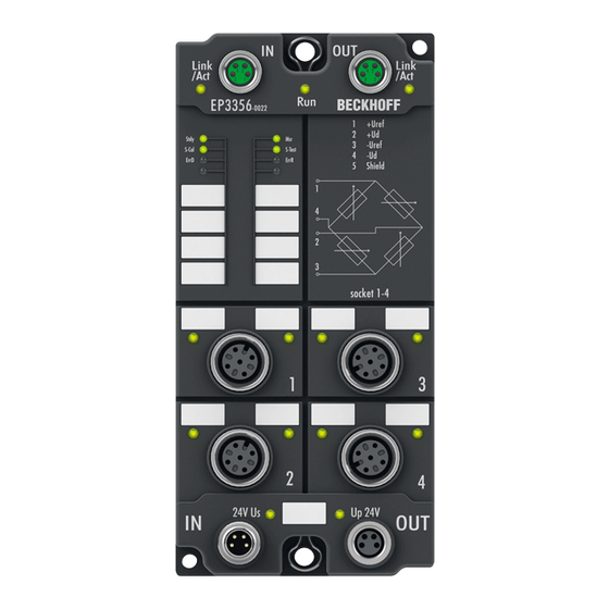
Product overview Product overview EP3356-0022 - Introduction Fig. 1: EP3356-0022 1-channel precise load cell analysis (resistor bridge), 24 bit The EP3356 EtherCAT Box enables direct connection of a resistor bridge or load cell in a 4-wire connection technology. The ratio between the bridge voltage U... -
Page 9: Ep3356-0022 - Technical Data
Product overview EP3356-0022 - Technical data Technical data EP3356-0022 Number of inputs 2, for 1 resistor bridge in full bridge technology Signal connection sockets [} 24] M12 Resolution 24 Bit, 32 bit presentation Conversion time 0.1 ms…250 ms, configurable, max. 10,000 samples/s Nominal voltage 24 V (-15 %/+20 %) -
Page 10: Additional Checks
Scope of supply Make sure that the following components are included in the scope of delivery: • 1x EtherCAT Box EP3356-0022 • 2x protective cap for EtherCAT socket, M8, green (pre-assembled) • 1x protective cap for supply voltage input, M8, transparent (pre-assembled) •... -
Page 11: Basic Principles Of Strain Gauge Technology
(piezo-resistive effect); k-factors of up to 200 can be achieved. Measurement of signals The change in resistance of an individual strain gauge can be determined in principle by resistance measurement (current/voltage measurement) using a 2/3/4-conductor measurement technique EP3356-0022 Version: 1.4... - Page 12 Measuring procedure The Beckhoff EL/KL335x Terminals and the EP3356 Box support only the constant excitation • Full bridge strain gauge at constant voltage (ratiometric measurement) Since the relative resistance change ΔR is low in relation to the nominal resistance R...
- Page 13 In relation to a 350 Ω measuring bridge this means a measuring error of > 0.1 %. Fig. 4: 4-conductor connection This can be remedied by a 6-conductor connection, in particular for precision applications (only possible with EL3356). Fig. 5: 6-conductor connection EP3356-0022 Version: 1.4...
- Page 14 5 of the M12 connector. EP3356-0022: No 6-conductor connection necessary The connection of a strain gauge over 4-conductor with the EP3356-0022 is sufficient because due to the shorter cable lengths no measurement errors occur.
- Page 15 Minimum application range or minimum measuring range in % of rated load This is the minimum measuring range/measuring range interval, which a calibratable load cell/set of scales must cover. Example: above load cell E = 10 kg; minimum application range e.g. 40 % E EP3356-0022 Version: 1.4...
- Page 16 = 350 Ω at an ambient temperature T = 20 °C (= 293 K) and a bandwidth of the measuring transducer of 50 Hz (and Boltzmann constant k = 1.38 * 10 J/K), the rms e = 16.8 nV. The peak-peak noise e is thus approx. e ~ 4* e = 67.3 nV. Version: 1.4 EP3356-0022...
- Page 17 • OIML (ORGANISATION INTERNATIONALE DE MÉTROLOGIE LÉGALE) www.oiml.org/en • PTB - Physikalisch-Technischen Bundesanstalt www.ptb.de/cms/ • www.eichamt.de • WELMEC - European cooperation in legal metrology www.welmec.org • DAkkS – Deutsche Akkreditierungsstelle www.dakks.de • Fachgemeinschaft Waagen (AWA) im Verband Deutscher Maschinen- und Anlagenbau VDMA www.vdma.org EP3356-0022 Version: 1.4...
-
Page 18: Mounting And Cabling
CuZn, gold-plated Power feed through max. 4 A Installation position variable Protection class IP65, IP66, IP67 (conforms to EN 60529) when screwed together Dimensions (H x W x D) approx. 126 x 60 x 26.5 mm (without connectors) Version: 1.4 EP3356-0022... -
Page 19: Fixing
• Protect the plug connectors against dirt during the assembly. Mount the module with two M4 screws in the centrally located fastening holes. 4.1.3 Tightening torques for plug connectors Screw connectors tight with a torque wrench. (e.g. ZB8801 from Beckhoff) Connector diameter Tightening torque 0.4 Nm 0.6 Nm... -
Page 20: Ethercat
For standardization, the core colors of the ZB9030, ZB9032 and ZK1090-3xxx-xxxx cables have been changed to the EN61918 core colors: yellow, orange, white, blue. So there are different color codes in circulation. The electrical properties of the cables have been retained when the core colors were changed. Version: 1.4 EP3356-0022... -
Page 21: Status Leds
(CAT5) according to EN 50173 or ISO/IEC 11801 should be used. EtherCAT uses four wires for signal transmission. Thanks to automatic line detection ("Auto MDI-X"), both symmetrical (1:1) or cross-over cables can be used between Beckhoff EtherCAT. Detailed recommendations for the cabling of EtherCAT devices EP3356-0022... -
Page 22: Supply Voltages
Plug Socket Input Forwarding Fig. 13: M8 connector Contact Function Description Core color Control voltage Brown Peripheral voltage White GND to U Blue GND to U Black The core colors apply to cables of the type: Beckhoff ZK2020-3xxx-xxxx Version: 1.4 EP3356-0022... -
Page 23: Status Leds
Vert. Faktor: 0,45 cm / V Vert. Faktor: 0,4 0,34 mm² Vert. Faktor: 0,45 cm / V Vert. Faktor: 0,5 mm² 0,25 mm² 0,34 mm² 0,75 mm² 0,5 mm² 0,75 mm² Cable length (m) Cable length (m) EP3356-0022 Version: 1.4... -
Page 24: Resistor Bridge
Do not earth the sensor cable shield at the sensor end If a shielded sensor cable is used, it should not be earthed at the sensor end. Otherwise measure- ment deviations may occur in certain system configurations. Version: 1.4 EP3356-0022... - Page 25 Mounting and Cabling Meanings of the LEDs Fig. 16: LEDs EP3356-0022 Color Meaning green This LED indicates the boxes operating state: State of the EtherCAT State Machine: INIT = Initialization of the box blinking State of the EtherCAT State Machine: PREOP = Setting for mailbox...
-
Page 26: Ul Requirements
To meet the UL requirements, EtherCAT Box Modules has to be operated only at an ambient temperature range of 0 to 55°C! Marking for UL All EtherCAT Box Modules certified by UL (Underwriters Laboratories) are marked with the following label. Fig. 17: UL label Version: 1.4 EP3356-0022... -
Page 27: Commissioning/Configuration
Commissioning/Configuration Commissioning/Configuration Integration in TwinCAT The procedure for integration in TwinCAT is described in this Quick start guide. EP3356-0022 Version: 1.4... -
Page 28: Ethercat Slave Process Data Settings (Pdo)
To this end the EtherCAT master (Beckhoff TwinCAT) parameterizes each EtherCAT slave during the start-up phase to define which process data (size in bits/bytes, source location, transmission type) it wants to transfer to or from this slave. - Page 29 (EP3356)` (0022): `PREOP to SAFEOP`failed! Error: `check device state for SAFEOP`, AL Status `0x0012`read and 0x0004` expected. AL status code `0x001e – invalid SM IN cfg` This error mes- sage „invalid SM IN cfg“ or „invalid SM OUT cfg“ provides an indication of the reason for the failed start. EP3356-0022 Version: 1.4...
-
Page 30: Basic Function Principles
The measuring functions of the EP3356 can be described as follows: • The EP3356-0022 Analog Input Box are used to acquire the supply voltage to a load cell as a reference voltage, and the differential voltage that is proportional to the force acting on the cell. - Page 31 • the minimum permissible assigned EtherCAT cycle time for the EP3356 is 100 µs. • If the EP3356-0022 is to be used in Distributed Clocks mode: ◦ DC must be activated ◦ the Process data [} 54] Timestamp must be activated. The filter functionality is not available then.
- Page 32 • The filter with IIR characteristics is a discrete time, linear, time invariant filter that can be set to eight levels (level 1 = weak recursive filter, up to level 8 = strong recursive filter). The IIR can be understood to be a moving average value calculation after a low-pass filter. Version: 1.4 EP3356-0022...
- Page 33 Commissioning/Configuration Fig. 23: Step response and Bode diagramm of the IIR filter EP3356-0022 Version: 1.4...
- Page 34 Parameterization takes place via the CoE entries 0x8000:13 and 0x8000:14 [} 66]. Evaluation takes place according to 2 parameters: • The "Dynamic filter change time" object (0x8000:13) [} 66] is used to set the time interval at which the existing signal is re-evaluated. Version: 1.4 EP3356-0022...
- Page 35 ) ) * E (1.1) Calculation of the weight (1.2) Scaling factor (e.g. factor 1000 for rescaling from kg to g) * (G / 9.80665) (1.3) Influence of acceleration of gravity x Gain - Tara (1.4) Gain and Tare EP3356-0022 Version: 1.4...
- Page 36 The EP3356 then maps the input signal with the corresponding latency for further processing, for which reason faster querying of the sampling unit at shorter intervals than the latency (EP3356 allows up to 100 µs) makes sense for true-to-detail mapping of the analog input signal. Version: 1.4 EP3356-0022...
- Page 37 It is not possible to change the specified latency. Beyond that the following are individually adjustable in each mode via CoE • activation of the averager • activation of the filter • type of filter Fig. 26: Setting parameters in CoE belonging to the individual modes EP3356-0022 Version: 1.4...
- Page 38 "Sample mode" in the EP3356 in relation to the processing of the analog values. The mode change takes about 30 ms, during which time the measured values are invalid and indicate this by the status byte. Fig. 27: Sample mode switching Version: 1.4 EP3356-0022...
-
Page 39: Application Notes
PLC, they are not components of the EP3356. In the following example (recorded with Scope2) impulses on a 15 kg load cell are recorded; the filter is wide open at IIR1 so that steep edges occur in the signal. EP3356-0022 Version: 1.4... - Page 40 • scales of the accuracy class I to III are to be realized • scales that are generally independent of acceleration due to gravity are to be realized then one should check whether the gravity correction needs to be adapted via object 0x8000:26 [} 66]. Version: 1.4 EP3356-0022...
- Page 41 The EP3356 cannot be officially calibrated as individual device. However, it can be integrated as element in applications that can then be equipped by the integrator with the required characteristics for official calibration capability using appropriate means. EP3356-0022 Version: 1.4...
-
Page 42: Calibration And Adjustment
10 seconds, execute the command "0x0101" (257dec) on CoE object 0xFB00:01 [} 64]. This command causes the current mV/V value (0x9000:11 [} 66]) to be entered in the "Zero balance" ob- ject. Check: CoE objects 0xFB00:02 [} 64] and 0xFB00:03 [} 64] must contain "0" after execution Version: 1.4 EP3356-0022... - Page 43 The values modified during the theoretical and practical calibration are stored in a local EEPROM. This can be written to up to 1 million time. In order to prolong the life of the EEPROM, therefore, the commands should not be executed cyclically. EP3356-0022 Version: 1.4...
- Page 44 Manager: "01 00"). This sets the tare object (0x8000:22 [} 66]) such that the display value is 0. Note: in the case of a device restart (INIT → OP) the tare is not deleted. In addition this tare can be executed via the control word: Version: 1.4 EP3356-0022...
- Page 45 The following commands can be transferred to the box via the CoE entry 0xFB00:01 [} 64]. Command Comment 0x0101 Execute zero balance 0x0102 Execute calibration 0x0001 Execute tare procedure (value is NOT saved in the boxes EEprom) 0x0002 Execute tare procedure (value is saved in the boxes EEprom) EP3356-0022 Version: 1.4...
-
Page 46: Notices On Analog Specifications
Analogous to pointing devices this is the measuring scale (see IEC 61131) or also the dynamic range. For analog I/O devices from Beckhoff the rule is that the limit with the largest value is chosen as the full scale value of the respective product (also called the reference value) and is given a positive sign. This applies to both symmetrical and asymmetrical measuring spans. - Page 47 In particular this also applies to SE, even though the term suggest that only one wire is required. • The term "electrical isolation" should be clarified in advance. Beckhoff IO modules feature 1…8 or more analog channels; with regard to the channel connection a distinction is made in terms of: ◦...
- Page 48 The property of electrical isolation indicates whether the channels are directly connected to each other. • Beckhoff terminals/boxes always feature electrical isolation between the field/analog side and the bus/ EtherCAT side. In other words, if two analog terminals/boxes are not connected via the power contacts, the modules are effectively electrically isolated.
- Page 49 One or two further sensor cables are used for the signal transmission of the current loop: 1. sensor cable: according to the Beckhoff terminology such sensors are to be connected to ‘single- ended’ inputs in 3 cables with +/-/Signal lines and if necessary FE/shield 2.
- Page 50 Commissioning/Configuration Fig. 34: 2/3/4-wire connection as single-ended or differential connection technology Version: 1.4 EP3356-0022...
-
Page 51: Voltage Measurement
CoE. The user calibration (CoE 0x80n0:17 [} 64] [offset], 0x80n0:18 [} 64] [gain]) or the user scaling (CoE 0x80n0:11 [} 64] [offset], 0x80n0:12 [} 64] [gain]) can be used for this. EP3356-0022 Version: 1.4... - Page 52 In the voltage measuring mode the EL3356 is to be connected to external GND with a single-ended connection. In addition the internal GND reference is to be closed by the CoE switch SymmetricRef- erencePotential. The EP3356 “supply” is not usable because the box internally generated 10 V. Version: 1.4 EP3356-0022...
-
Page 53: Distributed Clocks Mode
10.5 kSps or 105.5 kSps The minimum permissible EtherCAT cycle time is 100 µs for the EP3356 with and without DC mode. Time stamp See Notes on latency regarding [} 30] the time when the actual timestamp is acquired. EP3356-0022 Version: 1.4... -
Page 54: Process Data
The process data of the EP3356 are set up in the TwinCAT System Manager. The individual PDOs can be activated or deactivated separately. The "Process data" tab is used for this (visible only if the box is selected on the left). Version: 1.4 EP3356-0022... - Page 55 In order to simplify the configuration, typical configuration combinations of process data are stored in the device description. The predefined configurations can be selected in the process data overview. Therefore the function is available only if the ESI/XML files are saved in the system (downloadable from the Beckhoff website).
- Page 56 • 2x AnalogIn (Standard): 2-channel voltage measurement, 32-bit integer voltage value with additional information (under-range, over-range, error, TxPdoToggle) • 2x AnalogIn (Compact): 2-channel voltage measurement, 32-bit integer voltage value only Default process image The default process image is standard (INT32). Fig. 37: Default process image, EP3356 Version: 1.4 EP3356-0022...
- Page 57 The format matches the REAL format of IEC 61131-3, which in turn is based on the REAL format of IEC 559. A REAL number (single precision) is defined as follows (See also Beckhoff InfoSys: TwinCAT PLC Control: standard data types). In accordance with IEC 61131 this 32-bit variable can be directly linked with a FLOAT variable of the PLC.
- Page 58 Fixed-point representation of the load The display of the load value can also be converted already in the box into a point representation. To do this the input PDOs are to be changed as follows: Fig. 38: Load value in fixed-point representation Version: 1.4 EP3356-0022...
- Page 59 The format matches the REAL format of IEC 61131-3, which in turn is based on the REAL format of IEC 559. A REAL number (single precision) is defined as follows (See also Beckhoff InfoSys: TwinCAT PLC Control: standard data types). This 32-bit variable can be linked directly with a FLOAT variable of the PLC according to IEC61131.
- Page 60 DcInputShift indicates by how many nanoseconds [ns] before or after the global Sync the box determines your process data. For further information on this, see the EtherCAT system description. Since the EP3356 is not DC-triggered but determines the timestamp itself, these values have no meaning in the EP3356. Version: 1.4 EP3356-0022...
- Page 61 PDOs 0x1600 (de- RMB Control (Resistor Measure- 0x7000:01 [} 65] - Start calibration fault) ment bridge) 0x7000:02 [} 65] - Disable calibration 0x7000:03 [} 65] - Input freeze 0x7000:04 [} 65] - Sample Mode (only EL3356-0010/EP3356-0022) 0x7000:05 [} 65] - Tara EP3356-0022 Version: 1.4...
-
Page 62: Object Description And Parameterization
EtherCAT XML Device Description The display matches that of the CoE objects from the EtherCAT XML Device Description. We rec- ommend downloading the latest XML file from the download area of the Beckhoff website and in- stalling it according to installation instructions. - Page 63 This interval is always a multiple (default: 10 ) of the calibration interval (0x8000:31So the delivery state of the testing interval result from 10 x 180 s = 1800 s. The self test can be prevented by setting the process data bit "Disable calibration" EP3356-0022 Version: 1.4...
- Page 64 - 0x0002 Tara setting (Data are saved into the EEPROM) see commands [} 30] FB00:02 Status State of the current executed command UINT8 0x00 (0 0: Command executed without errors 255: Execution of command FB00:03 Response Optional return value of the command OCTET- STRING[4] Version: 1.4 EP3356-0022...
- Page 65 6000:12 Value (Real) Measuring value as REAL REAL32 0x00000000 6000:13 Timestamp Timestamp of current measuring value (only UINT64 EL3356-0010/EP3356-0022 in DC-Mode) Input data Index 6010, 6020 AI Inputs Index (hex) Name Meaning Data type Flags Default 60n0:0 AI Inputs Max. subindex...
- Page 66 Meaning Data type Flags Default 1009:0 Hardware version Hardware version of the EtherCAT slave STRING Index 100A Software version Index (hex) Name Meaning Data type Flags Default 100A:0 Software version Firmware version of the EtherCAT slave STRING Version: 1.4 EP3356-0022...
- Page 67 0x06 (6 1800:06 Exclude TxPDOs This entry contains the TxPDOs (Index of the Tx- OCTET- 04 1A 05 1A 06 PDO Mapping objects) which shall not be trans- STRING[10] 1A 07 1A 00 00 mitted with TxPDO 1 EP3356-0022 Version: 1.4...
- Page 68 0x06 (6 1807:06 Exclude TxPDOs This entry contains the TxPDOs (Index of the Tx- OCTET- 06 1A 00 1A 01 PDO Mapping objects) which shall not be trans- STRING[10] 1A 02 1A 03 1A mitted with TxPDO 8 Version: 1.4 EP3356-0022...
- Page 69 Index 1A03 RMB TxPDO-Map Timestamp Index (hex) Name Meaning Data type Flags Default 1A03:0 RMB TxPDO-Map Timestamp PDO Mapping Value Timestamp UINT8 0x01 (1 1A03:01 SubIndex 001 1. PDO Mapping entry (object 0x0000, entry UINT64 0x0000:00, 64 0x00) EP3356-0022 Version: 1.4...
- Page 70 Sync-Manager Type Channel 2: Mailbox Read UINT8 0x02 (2 1C00:03 SubIndex 003 Sync-Manager Type Channel 3: Process Data UINT8 0x03 (3 Write (Outputs) 1C00:04 SubIndex 004 Sync-Manager Type Channel 4: Process Data UINT8 0x04 (4 Read (Inputs) Version: 1.4 EP3356-0022...
- Page 71 TxPDO Mapping object) (6656 1C13:02 Subindex 002 2. assigned TxPDO (contains the index of the UINT16 0x1A01 corresponding TxPDO Mapping object) (6657 1C13:03 Subindex 003 3. assigned TxPDO (contains the index of the UINT16 corresponding TxPDO Mapping object) EP3356-0022 Version: 1.4...
- Page 72 Number of the too short distances between UINT16 0x0000 (0 SYNC0 and SYNC1 Event (only in DC Mode) 1C32:20 Sync error TRUE: In the last cycle the synchronization was BOOLEAN 0x00 (0 not correct (only in DC-Mode) Version: 1.4 EP3356-0022...
- Page 73 Index spacing of the objects of the individual UINT16 0x0010 (16 channels F000:02 Maximum number of modules Number of channels UINT16 0x0001 (1 Index F008 Code word Index (hex) Name Meaning Data type Flags Default F008:0 Code word reserved UINT32 0x00000000 EP3356-0022 Version: 1.4...
- Page 74 Index F010 Module list Index (hex) Name Meaning Data type Flags Default F010:0 Module list Max. subindex UINT8 0x03 (3 F010:01 SubIndex 001 UINT32 0x00000172 (370 F010:02 SubIndex 002 AI UINT32 0x0000012C (300 F010:03 SubIndex 003 AI UINT32 0x0000012C (300 Version: 1.4 EP3356-0022...
-
Page 75: Example Program
In this example program an EP3356 is addressed by a PLC program (for TwinCAT 2). The Zip-file (https:// infosys.beckhoff.com/content/1033/ep3356/Resources/zip/1856737419.zip) contains the PLC*.pro and the System Manager*.tsm. The box can be operated via simple visualization; the function InputFreeze is programmed out by way of example. - Page 76 Commissioning/Configuration Fig. 41: EP3356: Connection of the load sensor/full bridge The sensor power supply of 10 V is produced in EP3356. Version: 1.4 EP3356-0022...
- Page 77 (see the following two figures) Fig. 42: Searching the Ethernet adapter Fig. 43: Selection and confirmation of the Ethernet adapter • Activation of the configuration and confirmation (see the following two figures) Fig. 44: Activation of the configuration EP3356-0022 Version: 1.4...
- Page 78 • In TwinCAT PLC, under the "Project" menu, select "Rebuild all" to compile the project (see following figure) Fig. 48: Compile project In TwinCAT PLC: log in with the "F11" button, confirm loading the program (see following figure), run the program with the "F5" button Version: 1.4 EP3356-0022...
- Page 79 Commissioning/Configuration Fig. 49: Confirming program start EP3356-0022 Version: 1.4...
-
Page 80: Restoring The Delivery State
Fig. 51: Entering a restore value in the Set Value dialog Alternative restore value In some older terminals / boxes the backup objects can be switched with an alternative restore value: Decimal value: 1819238756 Hexadecimal value: 0x6C6F6164 An incorrect entry for the restore value has no effect. Version: 1.4 EP3356-0022... -
Page 81: Appendix
(ph-Value > 12) > 40°C: not resistant Acetic acid not resistant Argon (technical clean) resistant • resistant: Lifetime several months • non inherently resistant: Lifetime several weeks • not resistant: Lifetime several hours resp. early decomposition EP3356-0022 Version: 1.4... -
Page 82: Accessories
Torque cable key for M12 / wrench size 13 for ZB8801-0000 ZB8801-0003 Torque cable key for M12 field assembly / wrench size 18 for ZB8801-0000 Further accessories Further accessories can be found in the price list for fieldbus components from Beckhoff and online at https://www.beckhoff.com. Version: 1.4 EP3356-0022... -
Page 83: Version Identification Of Ethercat Devices
Production lot/batch number/serial number/date code/D number The serial number for Beckhoff IO devices is usually the 8-digit number printed on the device or on a sticker. The serial number indicates the configuration in delivery state and therefore refers to a whole production batch, without distinguishing the individual modules of a batch. - Page 84 • IP67: EtherCAT Box • Safety: TwinSafe • Terminals with factory calibration certificate and other measuring terminals Examples of markings Fig. 52: EL5021 EL terminal, standard IP20 IO device with serial/ batch number and revision ID (since 2014/01) Version: 1.4 EP3356-0022...
- Page 85 Appendix Fig. 53: EK1100 EtherCAT coupler, standard IP20 IO device with serial/ batch number Fig. 54: CU2016 switch with serial/ batch number Fig. 55: EL3202-0020 with serial/ batch number 26131006 and unique ID-number 204418 EP3356-0022 Version: 1.4...
- Page 86 Fig. 57: EP1908-0002 IP67 EtherCAT Safety Box with batch number/ date code 071201FF and unique serial number 00346070 Fig. 58: EL2904 IP20 safety terminal with batch number/ date code 50110302 and unique serial number 00331701 Fig. 59: ELM3604-0002 terminal with unique ID number (QR code) 100001051 and serial/ batch number 44160201 Version: 1.4 EP3356-0022...
- Page 87 6.3.1 Beckhoff Identification Code (BIC) The Beckhoff Identification Code (BIC) is increasingly being applied to Beckhoff products to uniquely identify the product. The BIC is represented as a Data Matrix Code (DMC, code scheme ECC200), the content is based on the ANSI standard MH10.8.2-2016.
- Page 88 Example of composite information from item 1 to 4 and 6. The data identifiers are marked in red for better display: An important component of the BIC is the Beckhoff Traceability Number (BTN, item no. 2). The BTN is a unique serial number consisting of eight characters that will replace all other serial number systems at Beckhoff in the long term (e.g.
- Page 89 Beckhoff's branch offices and representatives Please contact your Beckhoff branch office or representative for local support and service on Beckhoff products! The addresses of Beckhoff's branch offices and representatives round the world can be found on her internet pages: http://www.beckhoff.com You will also find further documentation for Beckhoff components there.
- Page 91 More Information: www.beckhoff.com/ep3356/ Beckhoff Automation GmbH & Co. KG Hülshorstweg 20 33415 Verl Germany Phone: +49 5246 9630 info@beckhoff.com www.beckhoff.com...
Need help?
Do you have a question about the EP3356-0022 and is the answer not in the manual?
Questions and answers