
Related Manuals for Comtech EF Data C


Summary of Contents for Comtech EF Data C
- Page 1 HPOD C, X, Ku High-Powered Outdoor Amplifier Installation and Operation Manual Part Number MN/HPOD.IOM Revision 2...
-
Page 3: Installation And Operation Manual
HPOD C, X, Ku High-Powered Outdoor Amplifier Installation and Operation Manual Comtech EF Data is an ISO 9001 Registered Company Part Number MN/HPOD.IOM REVISION 2 5/15/2007... - Page 4 HPOD Revision 2 Preface MN/HPOD.IOM...
- Page 5 480.333.2200 (Main Comtech EF Data Number) 480.333.4357 (Customer Support Desk) 480.333.2161 FAX To return a Comtech EF Data product (in-warranty and out-of-warranty) for repair or replacement: • the Comtech EF Data Customer Support Department. Be prepared to supply the Contact Customer Support representative with the model number, serial number, and a description of the problem.
-
Page 6: Table Of Contents
2.1 Interface Connectors ............................2–1 2.2 Turning On the SSPA............................2–6 CHAPTER 3. THEORY OF OPERATION ..............3–1 3.1 SSPA Block Diagram............................3–1 3.2 SSPA Module ..............................3–3 3.3 Cooling System..............................3–3 3.4 Monitor and Control (M&C)..........................3–3 3.5 Power Supply ..............................3–4 3.6 Block Up Converter Input Option ........................3–4... - Page 7 HPOD Revision 2 Preface MN/HPOD.IOM CHAPTER 4. CUSTOMER COMMANDS ..............4–1 4.1 Introduction ...............................4–1 4.2 RF Input Level ..............................4–1 4.3 Attenuator Control ............................4–1 4.4 Mute Control..............................4–1 4.5 Faults ..................................4–2 4.6 Power Detector..............................4–2 4.7 Some Common Commands..........................4–3 4.8 Remote Control Protocol and Structure......................4–3 4.9 RS-485.................................4–3 4.10 RS-485 (full duplex) summary: ........................4–4 4.11 RS-232................................4–4...
- Page 8 HPOD Revision 2 Preface MN/HPOD.IOM B.3 1:2 Mode ................................B–2 APPENDIX C. 1:1 HPOD SERIES REDUNDANCY TEST........C–1 C.1 Connection................................C–1 C.2 Operation................................C–2 viii...
-
Page 9: Revision
MN/HPOD.IOM BOUT THIS ANUAL This manual provides installation and operation information for the Comtech EF Data HPOD. This is a technical document intended for earth station engineers, technicians, and operators responsible for the operation and maintenance of the HPOD. ONVENTIONS AND... - Page 10 HPOD’s power supply. However, if the installation will be in an area with a high probability of lightning strikes, Comtech EF Data recommends the installation of surge suppression on the RF and IF cables. One source of these suppressors is PolyPhaser (www.polyphaser.com)
- Page 11 Comtech EF Data Corporation, would affect the reliability or detracts from the performance of any part of the product, or is damaged as the result of use in a way or with equipment that had not been previously approved by Comtech EF Data Corporation.
- Page 12 The buyer shall pass on to any purchaser, lessee, or other user of Comtech EF Data Corporation’s products, the aforementioned warranty, and shall indemnify and hold harmless Comtech EF Data...
-
Page 13: Chapter 1. Introduction
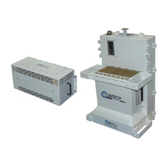
Chapter 1. INTRODUCTION 1.1 I NTRODUCTION The High-Power Outdoor (HPOD) Solid-State Power Amplifier (SSPA) shown in Figure 1-1 delivers its rated power, guaranteed, at the 1 dB compression point, to the transmit waveguide flange. It provides a cost effective, more reliable replacement for TWT amplifiers in satellite communications. -
Page 14: Field Replaceable Power Supply
EDUNDANCY ONTROLLER Each Comtech EF Data HPOD has the ability to function as a 1+1 (one backup for one primary) and 1+2 (one backup for two primary) redundant controller in the backup mode. The optional redundancy configuration is implemented by attaching a ganged waveguide/coax transfer switch(es) to the input and output connectors of the amplifiers with a combination coaxial cable and waveguide kit. -
Page 15: Option Free
Introduction 1.6 O PTION Comtech EF Data’s HPOD series of SSPAs come equipped with useful features that other manufacturers offer as options. Included in the base price are temperature compensation, sample ports, power monitor, field replaceable power factor corrected supply, and full remote monitor and control capabilities. -
Page 16: Specifications
BUC option ± 0.30 dB Operating Humidity 0 to 100% condensing -40 to +55°C ± 1.0 dB Altitude 10,000 ft above sea level (derated 2°C/ 1000 with BUC option ± 1.5 dB ft AMSL) Third Order Intermodulation Power Requirements Products... -
Page 17: Chapter 2. System Operation
2.1 I NTERFACE ONNECTORS Figure 2-1. Interface Connectors 2.1.1 C J1: RF IN ONNECTOR The RF Input connector is a type N female. Typical input levels (-30 dBm) depend on desired output power and unit attenuation. To prevent damage to the SSPA, RF input levels should not exceed +15 dBm. - Page 18 HPOD Revision 2 System Operation 2.1.2 C J2: RF OUT ONNECTOR The RF Output connector is a waveguide interface. The flange is described below according to the frequency range of the unit. Table 2-1. Waveguide Output Flange Unit Frequency Band...
- Page 19 J10 and its mate are contained in the table below. Table 2-2. Connector J10 Pinout Description No Connect No Connect Mating connector: CA3106E2222SB, CEFD PN CN/CA3106E2222SB 2.1.4 C J3: AC P ONNECTOR OWER AINS Before applying AC power to the unit, make sure the waveguide output of the amplifier is properly loaded or terminated.
- Page 20 The Redundant Loop Connector J4 is located near the waveguide output and is only utilized in configurations where the SSPA controls waveguide switching. In alternate configurations, such as “chain switching”, another system block or external M&C controls the waveguide switching. In this case, the connector remains unused and the protective cap should be left attached.
- Page 21 HPOD Revision 2 System Operation 2.1.6 C J6: COM 1, R ONNECTOR EMOTE COMMUNICATIONS AND DISCRETE CONTROL PORT The COM 1/ Discrete Control connector J6 is the primary input for controlling and monitoring the SSPA. It is a 19-pin circular connector, type MS3112E14-19S. The pin- out specification is contained in Table 2-5.
-
Page 22: Turning On The Sspa
HPOD Revision 2 System Operation 2.1.8 C J9: O ONNECTOR UTPUT AMPLE The Output sample port connector is a type N female. It provides a nominal -40 dB sample of the output signal. A calibration label is provided near the connector that shows the actual coupling values vs. -
Page 23: Chapter 3. Theory Of Operation
A block diagram of the SSPA is shown on the following page in Figure 3-1. The major components of the unit are: • SSPA Module • Cooling System • Monitor and Control (M&C) • Power Supply (Power Factor Corrected and Removable/Field Replaceable) 3–1... - Page 24 HPOD Revision 2 Theory of Operation MN/HPOD.IOM BLOCK DIAGRAM OUTPUT SAMPLE INPUT SAMPLE SSPA MODULE RF INPUT OUTPUT (W/G) CUST.GAIN TEMP CTRL COMP OUTPUT 10V A POWER DETECTOR 10V B POWER CONDITIONING & CONTROL CONTROL & MONITOR Interlock -5.8V +5.8V COM/ DISCRETE CONTROL...
-
Page 25: 3.2 Sspa Module
The M&C is also capable of acting as a controller in certain 1:1 or 1:2 redundant systems. When configured as the back-up SSPA in such a system, it communicates with the other SSPA(s) and toggles the waveguide switches as necessary. -
Page 26: Power Supply
The +24V output powers the cooling fans and is the source of power for waveguide switching when the SSPA is used in redundant configurations. The +5 and +15 voltages are used to operate the M&C board and other overhead functions. 3.6 B... -
Page 27: Chapter 4. Customer Commands
Chapter 4. CUSTOMER COMMANDS 4.1 I NTRODUCTION This section describes the operating features of the SSPA. A few key parameters and procedures are summarized, followed by detailed instructions of remote control communication commands. 4.2 RF I NPUT EVEL The required RF input level to reach the full rated output power of the SSPA is determined by the individual amplifier maximum gain and power rating. -
Page 28: Faults
• Either fan less than 25% of maximum speed • I2C internal bus communications fault • Thermal Shutdown - A temperature fault is indicated if the unit is ≥ +95°C. This creates a summary fault and will cause the unit to mute itself and switch to the back-up unit (if in a redundant system). -
Page 29: Some Common Commands
HPOD Revision 1 Customer Commands MN/HPOD.IOM 4.7 S OMMON OMMANDS A few of the most common commands and queries are listed below. Full details for each of these are listed at the end of this section. • RMS = Retrieve Maintenance Status. Displays voltages, fan speeds, Heatsink temperature, output power monitor reading, etc. -
Page 30: Rs-232
HPOD Revision 1 Customer Commands MN/HPOD.IOM Each target has a unique address, and each time the controller transmits, in a framed ‘packet’ of data, the address of the intended recipient target is included. All of the targets receive the packet, but only one (the intended) will reply. The target enables its output line driver, and transmits its return data packet back to the controller in the other direction on the physically separate pair. - Page 31 HPOD Revision 1 Customer Commands MN/HPOD.IOM 4.13 P ACKET TRUCTURE Controller-to-target: Start of Packet Target Address Instruction Code Optional End of Packet Address De-limiter Code Qualifier Arguments < = or ? Carriage ASCII code 60 ASCII code 47 ASCII code Return 61 or 63 ASCII code 13...
- Page 32 HPOD Revision 1 Customer Commands MN/HPOD.IOM 4.13.3 I NSTRUCTION This is a three-character alphabetic sequence that identifies the subject of the message. Wherever possible, the instruction codes have been chosen to have some significance. This aids in the readability of the message, should it be displayed in its raw ASCII form. Upper case and lower case alphabetic characters may be used (A-Z, and a-z).
- Page 33 HPOD Revision 1 Customer Commands MN/HPOD.IOM Second, if the controller sends an instruction to set a parameter to a particular value, and, providing the value sent in the argument is valid, then the target will acknowledge the message by replying with MUT= (with no message arguments). The ‘?’...
-
Page 34: Remote Commands
HPOD Revision 1 Customer Commands MN/HPOD.IOM 4.7 R EMOTE OMMANDS Attenuation 4–9 Retrieve Alarm Status 4–15 Auto Fault Recovery 4–9 Retrieve Configuration Status 4–16 Auxiliary Mute Enable 4–9 Retrieve Equipment Type 4–16 Retrieve Firmware Number 4–16 Circuit Identification 4–10 Retrieve Maintenance Status 4–17 Clear All Stored Alarms 4–10... - Page 35 HPOD Revision 1 Customer Commands MN/HPOD.IOM Command Arguments for Query Response to Description of arguments Response to (Instruction Command or (Instruction query Parameter Type (Note that all arguments are ASCII numeric Command Code and Response to Code and (Target to codes, that is, ASCII codes between 48 and 57) (Target to controller) Query...
- Page 36 HPOD Revision 1 Customer Commands MN/HPOD.IOM Command Arguments for Query Response to Description of arguments Response to (Instruction Command or (Instruction query Parameter Type (Note that all arguments are ASCII numeric Command Code and Response to Code and (Target to codes, that is, ASCII codes between 48 and 57) (Target to controller) Query...
- Page 37 Where: aaaaa = attenuation in dB b = RF power amplifier state c = mute state, 0 = un-muted, 1 = muted d = online status e-e = redundancy state and mode fffff = gain offset in dB g = AFR...
- Page 38 = -5V Power Supply hhh.h = Fan #1 speed (in percent) iii.i = Fan #2 speed (in percent) jjj.j = Amplifier temperature in deg. C kkk.k = Amplifier 10V1 lll.l = Amplifier 10V2 mmm.m=Forward RF output power, in dBm Note: nnn.n will appear for Ref Voltage if...
- Page 39 HPOD Revision 1 Customer Commands MN/HPOD.IOM Command Arguments for Query Response to Description of arguments Response to (Instruction Command or (Instruction query Parameter Type (Note that all arguments are ASCII numeric Command Code and Response to Code and (Target to codes, that is, ASCII codes between 48 and 57) (Target to controller) Query...
- Page 40 HPOD Revision 1 Customer Commands MN/HPOD.IOM Command Arguments for Query Response to Description of arguments Response to (Instruction Command or (Instruction query Parameter Type (Note that all arguments are ASCII numeric Command Code and Response to Code and (Target to codes, that is, ASCII codes between 48 and 57) (Target to controller) Query...
- Page 41 HPOD Revision 1 Customer Commands MN/HPOD.IOM Command Arguments for Query Response to Description of arguments Response to (Instruction Command or (Instruction query Parameter Type (Note that all arguments are ASCII numeric Command Code and Response to Code and (Target to codes, that is, ASCII codes between 48 and 57) (Target to controller) Query...
- Page 42 HPOD Revision 1 Customer Commands MN/HPOD.IOM Command Arguments for Query Response to Description of arguments Response to (Instruction Command or (Instruction query Parameter Type (Note that all arguments are ASCII numeric Command Code and Response to Code and (Target to codes, that is, ASCII codes between 48 and 57) (Target to controller) Query...
- Page 43 HPOD Revision 1 Customer Commands MN/HPOD.IOM Command Arguments for Query Response to Description of arguments Response to (Instruction Command or (Instruction query Parameter Type (Note that all arguments are ASCII numeric Command Code and Response to Code and (Target to codes, that is, ASCII codes between 48 and 57) (Target to controller) Query...
- Page 44 HPOD Revision 1 Customer Commands MN/HPOD.IOM Command Arguments for Query Response to Description of arguments Response to (Instruction Command or (Instruction query Parameter Type (Note that all arguments are ASCII numeric Command Code and Response to Code and (Target to codes, that is, ASCII codes between 48 and 57) (Target to controller) Query...
- Page 45 HPOD Revision 1 Customer Commands MN/HPOD.IOM Command Arguments for Query Response to Description of arguments Response to (Instruction Command or (Instruction query Parameter Type (Note that all arguments are ASCII numeric Command Code and Response to Code and (Target to codes, that is, ASCII codes between 48 and 57) (Target to controller) Query...
- Page 46 HPOD Revision 1 Customer Commands MN/HPOD.IOM Command Arguments for Query Response to Description of arguments Response to (Instruction Command or (Instruction query Parameter Type (Note that all arguments are ASCII numeric Command Code and Response to Code and (Target to codes, that is, ASCII codes between 48 and 57) (Target to controller) Query...
- Page 47 HPOD Revision 1 Customer Commands MN/HPOD.IOM Command Arguments for Query Response to Description of arguments Response to (Instruction Command or (Instruction query Parameter Type (Note that all arguments are ASCII numeric Command Code and Response to Code and (Target to codes, that is, ASCII codes between 48 and 57) (Target to controller) Query...
- Page 48 HPOD Revision 1 Customer Commands MN/HPOD.IOM Notes: 4–22...
-
Page 49: Chapter 5. Maintenance
Chapter 5. Maintenance 5.1 P OWER UPPLY EMOVAL CEFD’s HPOD series of outdoor SSPAs features field-replaceable power supply modules. To remove the supply: Step Procedure Disconnect power from the SSPA Loosen the four captive fasteners as indicated in Figure 5-1. Note: Be certain to use an appropriate screwdriver, such as the one provided with the SSPA, to avoid damaging the fasteners. - Page 50 HPOD Revision 2 Maintenance MN/HPOD.IOM Loosen 4 captive screws to replace power supply Figure 5-1. Power Supply Replacement 5–2...
-
Page 51: Fan Removal
HPOD Revision 2 Maintenance MN/HPOD.IOM 5.2 F EMOVAL The fans utilized by the HPOD are designed for long life even in a harsh environment. They are still mechanical devices subject to wear and may need replacement after several years. In dusty environments, their removal facilitates clearing the heat sink of accumulated dust. - Page 52 HPOD Revision 2 Maintenance MN/HPOD.IOM To install the fan assembly: Step Procedure Visually inspect the exposed SSPA heat sink for any debris/blockage. Clean as required Connect the fan assembly’s circular connectors to the SSPA Place assembly on SSPA, ensuring proper alignment of the fasteners without any cable /fan interference.
-
Page 53: Dimensional Envelope
HPOD Revision 2 Maintenance MN/HPOD.IOM 5.3 S CHEDULED AINTENANCE Once a year (or sooner depending on environmental conditions), the SSPA heat sink should be cleaned. To perform this maintenance: Step Procedure Disconnect power from the SSPA Remove the fan assembly as previously described Remove the power supply as previously described Using compressed air, blow through the SSPA heat sink to remove any foreign object accumulation that may be obstructing airflow. - Page 54 HPOD Revision 2 Maintenance MN/HPOD.IOM %%c .375 5.49 11.49 4.00 13.38 10.97 Figure 5-4b. Dimensional Envelope POSITION IDENTICAL & Ku-BAND 8.94 FLANGE 8.94 2.42 9.07 7.19 17.88 Figure 5-4c. Dimensional Envelope 5–6...
- Page 55 HPOD Revision 2 Maintenance MN/HPOD.IOM 22.75 (57.79) 10.00 (25.4 13.94 (35.4) Ku-Band: 1.88 (4.77) C-Band: 1.25 (3.18) Figure 5-5. Dimensional Clearance for Redundant Units. 5–7...
- Page 56 HPOD Revision 2 Maintenance MN/HPOD.IOM Notes: 5–8...
- Page 57 WITCH The following figures and parts lists represent the phase combiner 1:1 redundant switch kits. • Figure A-1. Redundant 1:1 ODPA C-Band Assembly Kit, P//N KT/11799 • Figure A-2. Redundant 1:1 ODPA X-Band Assembly Kit, Pl/ KT/11387 • Figure A-3. Redundant 1:1 Ku-Band Kit, PL KT/11936-1 •...
-
Page 58: Appendix A. Assembly Kits
HPOD Revision 2 Assembly Kits MN/HPOD.IOM Table A-1. Parts List for Redundant 1:1 ODPA C-Band Assembly Kit P/N KT/11799-1 Item Part No. Description Qty. SW/WGS+28V137SC Waveguide, CPR137, 28V, Sealed 3 Form C Relay 1 FP/BR11798-1 Bracket, Switch and Load Mounting... - Page 59 HPOD Revision 2 Assembly Kits MN/HPOD.IOM Figure A-1. Redundant 1:1 ODPA C-Band Assembly Kit, P/N KT/11799 A–3...
- Page 60 FP/WG11308-1 Waveguide, 90 Degree, H-Bend, CPRG-112 Not Used RF/X-TERM850W Termination, Load, 850 Watt, CPRG112, with Crossguide Coupler, 40 dB Not Used GA/CPR112-R-F-C Gasket, Round, CPR112, Full Thickness, -14 thru –19 Not Used HW/8-32HEXNUT Nut, Hex 8-32 HW/8-FLT Washer, Flat S.S.
- Page 61 HPOD Revision 2 Assembly Kits MN/HPOD.IOM 13 4X Figure A-2. Redundant 1:1 ODPA X-Band Assembly Kit, P/N KT/11387 A–5...
- Page 62 Waveguide, Right FP/WG11934-1 Waveguide, Left FP/BR11933-1 Bracket, Switch FP/BR11424-1 Bracket, Mounting FP/BR11931-1 Bracket, Unistrut FP/BR11932-1 Bracket, Unistrut GA/WR75-R-F-C Gasket, Full Thickness GA/WR75-R-H-C Gasket, Half Thickness RF/TERM75/350W Waveguide, Termination Not Used Not Used Not Used Not Used Not Used Not Used...
- Page 63 HPOD Revision 2 Assembly Kits MN/HPOD.IOM SSPA's SHOWN FOR CLARITY ONLY Figure A-3. Redundant 1:1 Ku-Band Kit, P/N KT/11936-1 A–7...
- Page 64 Springnut HW/3/8-FLT Washer, Flat HW/3/8-SPLIT Washer, Split HW/3/8-16X1BLT Bolt, Hex-Head HW/6-FLT Washer, Flat HW/6-SPLIT Washer, Split HW/6-32X7/8SHCS Screw, Cap HW/6-32X1/2SHCS Screw, Cap GA/WR75-R-F-C Gasket, Full-Thickness GA/WR75-R-H-C Gasket, Half-Thickness FP/SP12360-1 Spacer (RHOS) HW/4-FLT Washer, Flat HW/4-SPLIT Washer, Split HW/440X3/8SHCS Screw A–8...
- Page 65 HPOD Revision 2 Assembly Kits MN/HPOD.IOM Figure A-4. Redundant 1:1 HPOD Ku-Band Switch/Waveguide Kit, PL KT/12337-1 A–9...
- Page 66 HPOD Revision 2 Assembly Kits MN/HPOD.IOM Table A-5. Parts List for Redundant 1:1 HPOD Mounting Kit, PL KT/12200-1 Item Part No. Description Qty. FP/BR11931-1 Bracket, Unistrut FP/BR11932-1 Bracket, Unistrut Not Used HW/3/8SPRINGNUT Springnut HW/3/8-FLT Washer, Flat HW/3/8-SPLIT Washer, Split HW/3/8-16X1BLT Bolt, Hex-Head - Item Not Illustrated.
- Page 67 HPOD Revision 2 Assembly Kits MN/HPOD.IOM Figure A-5. Redundant 1:1 HPOD Mounting Kit, PL KT/12200-1 A–11...
- Page 68 HPOD Revision 2 Assembly Kits MN/HPOD.IOM Table A-6. Parts List for Redundant 1:1 HPOD C-Band Switch/Waveguide Kit, PL KT/12201-1 Item Part No. Description Qty. FP/BR12242-1 Bracket, Mounting (RHOS) GA/CPA-137-R-H-C Gasket, Half-Thickness GA/CPR-137-R-F-C Gasket, Full-Thickness RF/C-TERM1000W Termination, Load FP/WG12241-1 Waveguide, Straight (RHOS)
- Page 69 HPOD Revision 2 Assembly Kits MN/HPOD.IOM Figure A-6. Redundant 1:1 HPOD C-Band Switch/Waveguide Kit, PL KT/12201-1 A–13...
- Page 70 HPOD Revision 2 Assembly Kits MN/HPOD.IOM Table A-7. Parts List for Unistrut Mount HPOD Mounting Kit, PL KT/12300-1 Item Part No. Description Qty. FP/BR12239-1 Bracket, Mounting (RHOS) HW/3/8SPRINGNUT Springnut HW/3/8-FLT Washer, Flat HW/3/8-SPLIT Washer, Split HW/3/8-16X1BLT Bolt, Hex-Head HW/5/16-18HEXNT Nut, Hex HW/5/16-Flat Washer, Flat HW/5/16-SPLIT...
- Page 71 HPOD Revision 2 Assembly Kits MN/HPOD.IOM Figure A-7. Uni Strut Mount HPOD Mounting Kit, PL KT/12300-1 A–15...
- Page 72 Assembly Kits MN/HPOD.IOM Table 8. Parts List for Redundant HPOD Top Assembly Mounting Kit, PL KT/12240-1 Item Part No. Description Qty. KT/12200-1 Mounting Kit, C-Band (RHOS) KT/12201-1 Mounting Kit, Redundant Figure A-8. Redundant HPOD Top Assembly Mounting Kit, PL KT/12240-1 A–16...
- Page 73 HPOD Revision 2 Assembly Kits MN/HPOD.IOM Item No. Part No. Nomenclature Included in other mounting kit Bracket, Unistrut (shown for clarity only) FP/BR0072 Bracket, Strap Tensioner FP/BR0070 Bracket, Strap-Termination Pole Mounting Kit FP/BR0071 Bracket, 1 1/4 Strap(trim to required length) FP/BR0069 Bracket, Strap-Fixed, Pole Mounting Kit HW/M8X1.25X25HEXSS...
- Page 74 HPOD Revision 2 Assembly Kits MN/HPOD.IOM Figure A-10. Typical 1:1 Switch and Mounting Kit A–18...
- Page 75 HPOD Revision 2 Assembly Kits MN/HPOD.IOM Figure A-10. Typical 1:1 Switch & Mounting Kit (Continued) Figure A-10. Typical 1:1 Switch & Mounting Kit (Continued) A–19...
- Page 76 HPOD Revision 2 Assembly Kits MN/HPOD.IOM Figure A-10. Typical 1:1 Switch & Mounting Kit (Continued) A–20...
- Page 77 HPOD Revision 2 Assembly Kits MN/HPOD.IOM Figure A-10. Typical 1:1 Switch & Mounting Kit (Continued) A–21...
- Page 78 HPOD Revision 2 Assembly Kits MN/HPOD.IOM This page intentionally left blank. A–22...
-
Page 79: Appendix B Redundancy
B.1 R EDUNDANCY PERATION The HPOD C-/Ku Band Outdoor Power Amplifiers can be used in a redundancy configuration by connecting the appropriate 1:1 or 1:2 redundancy cable to the Redundancy Loop (Connector J4). The mode of redundancy will be automatically detected by the cable that is installed by the user. -
Page 80: 1:2 Mode
The backup unit also stores an offset value for each of the 2 online units to be used when the backup unit replaces an active unit. This offset may be set with the SBO= command. For additional information, refer to Appendix C 1:1 HPOD Series Redundancy Test. B–2... - Page 81 HPOD C-/Ku-Band Outdoor Power Amplifier Revision 2 Redundancy MN/HPOD.IOM Command Arguments Query Response to (Instructio Description of arguments Response to Parameter for Command (Instruction query n Code (Note that all arguments are ASCII numeric codes, Command Type or Response Code and...
- Page 82 HPOD C-/Ku-Band Outdoor Power Amplifier Revision 2 Redundancy MN/HPOD.IOM Arguments Command Query Response to Description of arguments Response to Parameter (Instruction Command (Instruction query (Note that all arguments are ASCII numeric codes, Command Type Code and Code and (Target to...
-
Page 83: Appendix C. 1:1 Hpod Series Redundancy Test
COMM address is “1”. If required set it to “1” (SPA=0001). c. When complete, the SSPA connected to the “SSPA 1” end of the redundancy interlink cable should have RS-485 COMM address 1 and SSPA 2 will be COMM address 2. -
Page 84: Operation
Ensure either unit can throw the switch in both directions by sending the following commands a. <1/SSW=1 (the switch may or may not transition) b. <1/SSW=2 (the switch should transition) c. <1/SSW=1 (the switch should transition) d. <2/SSW=2 (the switch should transition) e. <2/SSW=1 (the switch should transition) C–2... - Page 85 0.621 — — — Temperature Conversions ° Fahrenheit ° Centigrade Unit Formulas — C = (F - 32) * 0.555 (water freezes) 32° Fahrenheit — F = (C * 1.8) + 32 (water boils) 212° Fahrenheit 273.1 — (absolute 0) -459.6°...
- Page 86 2114 85281 WEST TH STREET TEMPE ARIZONA 480 • 333 • 2200 PHONE 480 • 333 • 2161...
Need help?
Do you have a question about the C and is the answer not in the manual?
Questions and answers