
Related Manuals for ITech IT7900P Series


Summary of Contents for ITech IT7900P Series
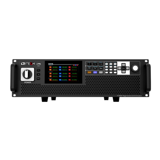
- Page 1 Programmable AC Power Supply IT7900P Series User Manual Model: IT7900P Version: V1.0/2022.08...
- Page 2 Notices Warranty Safety Notices © Itech Electronic, Co., Ltd. 2022 The materials contained in this No part of this manual may be document are provided “as is”, and reproduced in any form or by any is subject to change, without prior means ( including electronic storage notice, in future editions.
-
Page 3: Warranty
Warranty ITECH warrants that the product will be free from defects in material and workmanship under normal use for a period of one ( 1) year from the date of delivery ( except those described in the Limitation of Warranty below). - Page 4 Failure to comply with these precautions or specific warnings elsewhere in this manual will constitute a default under safety standards of design, manufacture and intended use of the instrument. ITECH assumes no liability for the customer’s failure to comply with these precautions.
-
Page 5: Environmental Conditions
To make accurate measurements, allow the instrument to warm up for 30 min. Regulatory Markings The CE mark indicates that the product complies with all the relevant European legal directives. The specific year ( if any) affixed refers to the year when the design was approved. Copyright ©ITECH Electronic Co., Ltd. -
Page 6: Waste Electrical And Electronic Equipment ( Weee) Directive
With reference to the equipment classifications described in the Annex 1 of the WEEE Directive, this instrument is classified as a “Monitoring and Control Instrument”. To return this unwanted instrument, contact your nearest ITECH office. Copyright ©ITECH Electronic Co., Ltd. -
Page 7: Compliance Information
2. Connection of the instrument to a test object may produce radiations beyond the specified limit. 3. Use high-performance shielded interface cable to ensure conformity with the EMC standards listed above. Safety Standard IEC 61010-1:2010/ EN 61010-1:2010 Copyright ©ITECH Electronic Co., Ltd. -
Page 8: Table Of Contents
5.6 Professional Anti-islanding Test Mode ....................... 47 5.7 Waveform Selection ............................48 5.8 Full 4-Quadrant Power Amplifier ........................49 5.9 Auto-range Function ............................49 5.10 Programmable Output Impedance ........................50 5.11 Sweep Function ..............................50 Copyright ©ITECH Electronic Co., Ltd. - Page 9 7.1.2 Set the communication interface ......................109 7.1.3 View the System Information ........................109 7.2 Configuration Menu Reference ........................109 7.3 Key Lock Function ............................. 112 7.4 Switching Local/Remote Mode ........................112 7.5 Save and Recall Operations ..........................113 Copyright ©ITECH Electronic Co., Ltd.
- Page 10 10.4 GPIB Interface (Optional) ..........................143 10.5 RS–232 Interface (Optional) ........................... 144 10.6 Commonly Used Commands Overview ......................145 10.7 Demo Software Introduction ......................... 146 Appendix ................................147 Specifications of Red and Black Test Lines ......................147 Copyright ©ITECH Electronic Co., Ltd.
-
Page 11: Chapter1 Overview
Chapter1 Overview This chapter introduces the front panel, the rear panel, key functions and LCD display function of the IT7900P series power supply, make sure that you can quickly know the appearance, instruction and the key function before you operate the power supply. Help you make better use of this series of power supply. -
Page 12: Optional Accessories
The IT7900P series supports the following optional accessories (sold separately), the details are as below: The interface expansion slot provided on the rear panel of the IT7900P series instrument allows users to flexibly expand according to their needs. Different interface cards can be selected to achieve different functions. -
Page 13: Instrument Size Introduction
1.4 Instrument Size Introduction The instrument should be installed at well-ventilated and rational-sized space. Please select appropriate space for installation based on the power supply size. IT7905P-350-30U/IT7906P-350-90/IT7909P-350-90/IT7912P-350-90/IT7915P-350-90 Model Copyright ©ITECH Electronic Co., Ltd. - Page 14 Overview IT7930P-350-180 Model Copyright ©ITECH Electronic Co., Ltd.
- Page 15 Overview IT7945P-350-270 Model Copyright ©ITECH Electronic Co., Ltd.
- Page 16 Overview Copyright ©ITECH Electronic Co., Ltd.
- Page 17 Overview IT7960P-350-360/IT7975P-350-450/IT7990P-350-540/IT79105P-350-630 Model Copyright ©ITECH Electronic Co., Ltd.
- Page 18 Overview IT79120P-350-720/IT79135P-350-810/IT79150P-350-900/IT79165P-350-990 Model Copyright ©ITECH Electronic Co., Ltd.
-
Page 19: Chapter2 Instrument Introduction
⚫ It is not advisable to push down the slope to prevent the cabinet from falling down due to the shift of the center of gravity. It is rec- ommended Copyright ©ITECH Electronic Co., Ltd. -
Page 20: Verifying The Shipment
⚫ ITECH 27U and 37U cabinets are equipped with hoisting rings as standard on the top. It is recommended to use a crane equipped with a four-leg hoisting belt structure for horizontal hoisting and moving, and ensure that the four hoisting belts are the same length to avoid cabinet skew during movement. -
Page 21: Front Panel
5 Number key 6 Up, down, left and right key and enter key 7 Rotary knob 8 Vent hole 2.4 Keyboard The keyboard introduction of IT7900P series Power Supply is shown as follows. Keys Description Print Used for saving screen images... - Page 22 Enter the Surge and Sag menu, used to Set the Surge/trapped Configuration. [Shift]+ (Surge&Sag) Enter the standard wave selection interface. [Shift]+ (Standard) [Shift]+[1](Log) Enter the data logging function menu. [Shift]+ [2] (Lock) Turn the keyboard lock on or off. Copyright ©ITECH Electronic Co., Ltd.
-
Page 23: Push-On Knob
[Shift]+ [7] (Help) Obtain the help information. 2.5 Push-on Knob The IT7900P series Power Supply provides a knob on the front panel as shown in the next figure. The functions of the posh-on knob is described as follows. ⚫... - Page 24 USB interface USB communication interface. system bus Used for communication between instruments in parallel operation feature. AC power input Used to connect AC power to start instrument. socket Copyright ©ITECH Electronic Co., Ltd.
- Page 25 Instrument Introduction The rear panel of IT7900P series 15U and above series cabinets are the same. Take IT7945P-350-270 as an example, the rear panel is introduced as shown below. 1: Output socket, which can be used when users need single-phase lower than...
-
Page 26: Chapter3 Installation
Connecting the power cord The standard power cord specifications for this series of 3U instruments are divided into the following types according to different regions: Copyright ©ITECH Electronic Co., Ltd. - Page 27 In case multiple units are connected to the same main AC distribution box. It is recommended to follow the suggestion connection diagram as below. Single phase input connecting: Multiple power supplies connect to three phase input: Copyright ©ITECH Electronic Co., Ltd.
- Page 28 L1, L2 and L3 terminals one by one. b) The yellow-green wire is grounding wire, which is connected to the protective grounding terminal (PE). Copyright ©ITECH Electronic Co., Ltd.
-
Page 29: Connecting Test Lines ( Optional)
⚫ Always use test lines provided by ITECH to connect the equipment. If test lines from other factories are used, please check that the test line can withstand maximum current. - Page 30 The connection diagram of single phase is shown as follow: NOTE When the output voltage has DC voltage, the output terminal L is positive, and N is negative. ⚫ The connection diagram of three phase is shown as follow: Copyright ©ITECH Electronic Co., Ltd.
- Page 31 1,200A, then 4 pieces of 360A red and black cables are required. 4. Thread the red and black test cables through the output terminals cover of the power system and install the cover. Copyright ©ITECH Electronic Co., Ltd.
- Page 32 Remote sense terminals of master module. The wiring method is the same as other models. ⚫ The connection diagram of single phase is shown as follow: NOTE When the output voltage has DC voltage, the output terminal L is positive, and N is negative. Copyright ©ITECH Electronic Co., Ltd.
- Page 33 For example, the maximum current is 1,200A, then 4 pieces of 360A red and black cables are required. 4. Thread the red and black test cables through the output terminals cover of Copyright ©ITECH Electronic Co., Ltd.
-
Page 34: Installing Fiber Cables (Only For It7930P-350-180)
Fiber optic cables cannot be flexed or folded. When the cable is too long and needs to be arranged, gently wrap the cable in a circle and gently tie it. As shown in the following figure, connect the System Bus between the master and slave by fiber cords. Copyright ©ITECH Electronic Co., Ltd. -
Page 35: Chapter4 Getting Started
The disconnect device must be close to the equipment, be easily accessible, and be marked as the disconnect device for this equipment. Copyright ©ITECH Electronic Co., Ltd. -
Page 36: Home-Screen Overview
User can adjust the power switch directly to turn on or turn off the instrument. The status of Power switch is as follows. The switching knob of the IT7900P series power supply allows the user to turn the power on by 90° clockwise or to turn the power off by 90° counterclockwise. - Page 37 Getting Started Single Phase Mode The meter interface of IT7900P series power supply is shown as follow. Status bar Voltage setting&meter value Frequency setting&meter value Display area of measuring data Three Phase Mode The meter interface of IT7900P three phase mode is shown as follow.
- Page 38 Multi-channel AC+DC Multi-channel AC mode mode Multi-channel DC+AC Multi-channel DC mode mode The AC source is in Surge&Sag function remote mode indicator External Simulation Test Record log Function LIST is running LIST is finished Copyright ©ITECH Electronic Co., Ltd.
-
Page 39: Touch Screen Introduction
Touch screen drag and corresponding functions are described as below. Convenient user quickly understand how to use this power supply. Copyright ©ITECH Electronic Co., Ltd. -
Page 40: Set Output Parameters
If the [On/Off] key light is on, indicates that the output is turned on. The VFD displays the meter value such as voltage, current, power and so on. If the [On/Off] key light is off, indicates that the output is turned off. The VFD Copyright ©ITECH Electronic Co., Ltd. - Page 41 Getting Started displays that the power supply state is OFF. Copyright ©ITECH Electronic Co., Ltd.
-
Page 42: Chapter5 Source Mode Operation
Source mode. 5.1 full 4-Quadrant output character The IT7900P series represent the newest generation of programmable, full four- quadrant grid simulators with full 100% of current rating in both source and sink mode, and provides energy recovery capability. -
Page 43: Select The Output Mode
The output mode can be set to AC/DC/ACDC/DCAC. 5.3 Select the Output Mode The IT7900P series has four output modes: AC, DC, AC+DC, DC+AC. It not only provides pure AC/DC output, but also can use AC+DC and DC+AC output modes to realize "AC output plus DC bias"... -
Page 44: Dc Output Mode
Source Mode Operation supply. The default set of IT7900P series power supply is AC Mode. Set the output parameters of the power supply in the main interface, including the output voltage, output frequency. ⚫ Press up/down keys to select setting value and then press Enter to confirm. -
Page 45: Ac+Dc Mode
If the output mode select to DC+AC Mode, the instrument will simulate DC and AC power supply, which can add AC component to DC voltage. Set the output voltage in the main interface, as shown in the figure below. Copyright ©ITECH Electronic Co., Ltd. -
Page 46: Current Limit Mode And Power Limit Mode
The Vac setting range is 10% of rated voltage. 5.4 Current Limit Mode and Power Limit Mode The IT7900P series power supply defaults to constant voltage CV output mode. The output voltage can be set in main interface. When the actual current value is higher than the setting current limit value, power supply works in current limit mode, and output voltage will be reduce. -
Page 47: Current Rms Protection
(rms) will turn off the output. How to Set Press [Shift]+[Config] (Protect) keys and enter to Protection menu. Press the up/down key or rotate the knob to select Current RMS protection Copyright ©ITECH Electronic Co., Ltd. -
Page 48: Set The Current Peak Protection
Limit factory setting is the rated output voltage/current/power of corresponding model of the power supply. Minimum is 0. Take the voltage limit setting for an example, the operating as follows: Press [Shift]+[Config] (Protect) keys and enter to Protection menu. Copyright ©ITECH Electronic Co., Ltd. -
Page 49: Over-Temperature Protection (Otp)
OPP mode. 5.6 Professional Anti-islanding Test Mode The IT7900P series provide a professional anit-islanding test mode. Users can adjust RLC parameters or configure the parameters of active power and reactive power to simulate islanding status between inverter and load when the main... -
Page 50: Waveform Selection
The interface will display the running time value in the island state. 5.7 Waveform Selection The user can set the output waveform in the config menu of IT7900 series power supply. Eight output waveforms below are available, user can select the Copyright ©ITECH Electronic Co., Ltd. -
Page 51: Full 4-Quadrant Power Amplifier
5.8 Full 4-Quadrant Power Amplifier The IT7900P series regenerative grid simulator can be used as a power amplifier to complete power hardware in the loop (PHIL) applications for microgrids, energy storage and new energy vehicles. The digital I/O or a standard suite of analog signal can be input via an external analog interface (optional) and then amplified without distortion to a real power waveshape. -
Page 52: Programmable Output Impedance
Sweep function is not applicable under DC mode and DCAC mode. The Sweep function is not supported in multi-channel mode. Operating steps Press [Shift] + [F-set](Sweep)on the front panel to enter the sweep interface, as shown in the figure below. Copyright ©ITECH Electronic Co., Ltd. - Page 53 Meter to observe the output parameters in the main interface. After sweeping, [On/Off] on the front panel will be off, and status will be displayed on LCD. You can press [Stop] on the Sweep interface to stop the Sweep function. Copyright ©ITECH Electronic Co., Ltd.
-
Page 54: List Function
Run/Stop: Run/stop the list function. Open: Select the List file to execute. New: Create a new List file. Edit: Edit present list file Delete: delete the present List file. Press [New] and enter to the List file edit interface. Copyright ©ITECH Electronic Co., Ltd. - Page 55 Save: Save the list file. Config: configure the list file to make it effective. Clear all: delete all of step information Trig source: select trigger source Click (More)… enter to advanced menu of list file. Copyright ©ITECH Electronic Co., Ltd.
-
Page 56: Select/Run List File
Press [Shift]+[V-set](list) on the front panel to enter the List function configuration interface. Press [Open], select the saved List01 csv file, and press [Enter] to enter the file. Press [On/Off] on the front panel, turn on the output. Press [Run] in the list function interface. Copyright ©ITECH Electronic Co., Ltd. -
Page 57: Import/Export List File
5.12.3 Import/Export List file Import List file IT7900P series support import list file function, The user can finish the editing of List file in Excel and import it into the software. This function simplifies the List file edit and facilitates user operation. - Page 58 Set the start phase angle of the surge/trap when the mode select to trigger. Angle width Set the period of the surge/trap. For example, start angle=30 degree, Angle width=30 degree, then, the waveform will execute surge/sag at 30 to 60 degree. Copyright ©ITECH Electronic Co., Ltd.
-
Page 59: Self-Defined Waveform Function
Sin wave voltage and test the usage of the DUT under this circumstance. THD includes built-in 30 waveforms and user - defined waveforms.The interface is shown below. Copyright ©ITECH Electronic Co., Ltd. - Page 60 Thd profile: THD file name Thd formula: Distortion factor calculation formula. %r: displaying harmonics in the form of percentage to the overall voltage amplitude of all harmonics. %f: displaying harmonics in the form of percentage to the fundamental voltage. Copyright ©ITECH Electronic Co., Ltd.
-
Page 61: Selfdefined
“-” delete the wave file. “ ” edit the wave file. Edit interface: Profile: user-defined file name Origin Symmetry: To select the waveform data type, you can select 512 origin symm/512 origin asymm /1024 points Copyright ©ITECH Electronic Co., Ltd. -
Page 62: Voltage Sampling
2.5 Connecting the Test Lines, and take the sampling DUT supply voltage signal as an example, the wiring diagram is shown below. Operation method Click Menu > Volt sample and enter to Voltage signals sampling interface, the display is shown below. Copyright ©ITECH Electronic Co., Ltd. - Page 63 Click Configure in the voltage sampling interface to enter the parameter setting interface. ⚫ Sampling rate: Sampling rate, indicating the sampling interval of data points. Setting range 1-50, unit kHz ⚫ Start Condition: setting the condition of sampling Imme: Sampling is executed immediately after clicking Run. Copyright ©ITECH Electronic Co., Ltd.
-
Page 64: Voltage Signals Simulation
Start mode: can be selected as immediate execution or trigger execution. Interval time: The interval between waveform repeats.This parameter is displayed only when start mode is selected for Imme. Repeat: Number of repeated execution of waveform Coefficient: Waveform amplification Coefficient DC: DC offset Copyright ©ITECH Electronic Co., Ltd. - Page 65 Delete: Delete the waveform file. Import: Import and save the waveform file to the power supply memory. Export: Export the waveform file to the U disk. Run: Start running waveform. Power output should be turned on before operation. Copyright ©ITECH Electronic Co., Ltd.
-
Page 66: Polyphase Function
Source Mode Operation 5.17 Polyphase Function The IT7900P series power supplies implement the frequency-locked and phase- locked function between power supplies through the digital IO interface or System bus interface, which achieve 6 phase& 12 phase power output. This power supply provides two ways to achieve multi-phase functionality: One is to connect the System bus interface between instruments directly ⚫... - Page 67 Set the phase deviation between the Phase Delay output phase and the external I/O input signal: 0-360°. Set the frequency difference upper Freq limit+ limit between the output frequency and the external I/O input signal. Copyright ©ITECH Electronic Co., Ltd.
-
Page 68: Connecting Digital I/O Method
Press [Shift] + (System) and enter to the system menu interface. Select I/O -> Digital IO-4: SYNC. Set one IT7900P power supply as a synchronization signal output to Sync- out, and the others set to Sync-out. Copyright ©ITECH Electronic Co., Ltd. - Page 69 Fiber: The slave is controlled by the master fiber. If in balance mode, the Phase Delay between the first instrument and the second intrument is set to 60° to achieve six-phase balanced output of 60° between six phases. Copyright ©ITECH Electronic Co., Ltd.
-
Page 70: Standard Iec Regulations
Source Mode Operation 5.18 Standard IEC Regulations IT7900P series AC/DC power supplies provide standard test curves in accordance with IEC 61000-4-11/4-13/4-14/4-28 regulations. It can be invoked directly by the user when testing IEC compliance tests. This function provides both the test curve that meets the standard requirements of regulations and the curve customization function. - Page 71 Voltage value of AC output. User can setting the voltage level according to the DUT requirements. Frequency Frequency value of AC output. Different regulatins have different definitions. This parameter can be set only for User defined categories. Copyright ©ITECH Electronic Co., Ltd.
- Page 72 Click Configure to enter the configuration interface of other parameters, and set the Rise time and Fall time. ⚫ Run/Stop running or stopping the regulation tests. You must enable the output before running. Otherwise, a message is displayed indicating that the output is not enabled. Copyright ©ITECH Electronic Co., Ltd.
-
Page 73: Chapter6 Operation And Application
The input mode can be select in the system menu. Press [Shift] + (System) enter to system menu. Copyright ©ITECH Electronic Co., Ltd. -
Page 74: Ac Input Mode
Select CC mode The initial default mode of IT8200 electronic load is the “CC” mode. This run mode can be set under Config menu interface as follows: Press [Config] and enter to the configuration menu. Copyright ©ITECH Electronic Co., Ltd. - Page 75 The user can press [Set] and set the input current value in the main interface of CC mode. Directly set the present value through the knob or press numeric keys to input the value. In case of wrong input by numeric keys, press delete the present input. Copyright ©ITECH Electronic Co., Ltd.
-
Page 76: Constant Resistance Mode (Cr)
1, as shown below. The Slope is R setting Input Voltage Load Current CR mode Voltage-current Relation in CR Mode Select CR mode Press [Config] and enter to the configuration menu. Select constant mode to Copyright ©ITECH Electronic Co., Ltd. -
Page 77: Constant Power Mode (Cp)
P (=V * I) at the set value. Input Voltage Set power value Load Current Voltage-current Relation of CP Mode Select CP mode Press [Config] and enter to the configuration menu. Select constant mode to Copyright ©ITECH Electronic Co., Ltd. -
Page 78: Constant Apparent Power Mode (Cs)
If the input voltage increases, the input current will decrease to keep the power S (=V * I) at the set value. Copyright ©ITECH Electronic Co., Ltd. - Page 79 Waveform (phase shift range: -90.0~90.0): select the waveform. Under CC mode, and Unit PF is off, Waveform can be select. ⚫ Crest Factor: CF range is 1.414~5, and the range is limited by peak value. Copyright ©ITECH Electronic Co., Ltd.
-
Page 80: Constant Current +Constant Resistance (Cc+Cr)
Press [Config] and enter to the configuration menu. Select constant mode to CC+CR. Under the config menu interface, the user can select Const Mode item and set the mode to CC+CR. ⚫ Const Mode: load mode Copyright ©ITECH Electronic Co., Ltd. -
Page 81: Circuit Emulation (Ce)
In this mode, the R L C parallel state is simulated and the circuit schematic is shown in the figure below. Rectifier single phase RLC This mode simulates a single-phase rectifier R L C circuit, and the circuit schematic is shown in the figure below. Copyright ©ITECH Electronic Co., Ltd. -
Page 82: Dc Load Function
DC mode. IT8600 electronic load can be operated in the following four modes: ⚫ Constant current mode (CC) ⚫ Constant voltage mode (CV) ⚫ Constant register mode (CR) Constant power mode (CP) ⚫ ⚫ CC+CV mode Copyright ©ITECH Electronic Co., Ltd. -
Page 83: Constant Current Mode (Cc)
In CP mode, the load will consume a constant power. See Figure as follow. If the input voltage rises, the input current will decline. The P (=V * I) will remain on the set power. Copyright ©ITECH Electronic Co., Ltd. -
Page 84: Complex Operation Mode
When the voltage rises to exceed the set constant resistance for sinking, it will switch to CR mode for sinking. The CV+CR mode can be applied to the LED simulation and test the LED power supply to get the LED current ripple parameters. Copyright ©ITECH Electronic Co., Ltd. - Page 85 The CP+CV mode is often used to UPS battery test, simulate the current change when the battery voltage is decaying. It can also be used to simulate the characteristics of the inputs of DC-DC converters and inverters. Copyright ©ITECH Electronic Co., Ltd.
-
Page 86: Rectified Mode
The user can choose waveform integrity, including full wave, positive half wave, negative half wave. In this mode, DC current can not be set. Setting method: Enter to System menu, set Rectified to On. Copyright ©ITECH Electronic Co., Ltd. - Page 87 Integrity set to Full, the waveform of the power input is rectified in full wave, as shown in the figure below. Integrity set to Positive, the waveform of the power input is rectified in positive half wave, as shown in the figure below. Copyright ©ITECH Electronic Co., Ltd.
- Page 88 If programmed is negative it will be a lagging power factor. The range of CF setting is 1.414~5, and the range of Phase shift changes by CF setting. The relationship graph is show as below. Copyright ©ITECH Electronic Co., Ltd.
-
Page 89: Waveform Selection
CF & Phase shift relationship 6.6 Waveform Selection The user can set the input waveform in the config menu of IT8200 series load. Eight input waveforms below are available, user can select the waveform in Config->Waveform menu. Copyright ©ITECH Electronic Co., Ltd. -
Page 90: C Phase Loss
⚫ Phase angle control when the input is turned off Off-mode ⚫ Phase Immediately ⚫ When On Phase is set to angle control and the angle is set to 270°, the waveform is shown below. Copyright ©ITECH Electronic Co., Ltd. -
Page 91: Sweep Function
Operating steps Press [Shift] + [F-set] (Sweep) on the front panel to enter the sweep interface, as shown in the figure below. Copyright ©ITECH Electronic Co., Ltd. - Page 92 Trigger-back-forth: Step switching according to trigger and scanning back and forth. Step time Set the step time. Repeat count Repeat count Waveform Select sweep waveform Sine Square Sawtooth Triangle Trapezoid Copyright ©ITECH Electronic Co., Ltd.
-
Page 93: Synchronization Function
(System) and enter to the system menu interface. Select I/O -> Digital IO-4: SYNC. Set one IT8200 load as a synchronization signal output to Sync-out, and the others set to Sync-out. 【Sync-in】: Synchronous input function, which is used to output frequency Copyright ©ITECH Electronic Co., Ltd. -
Page 94: List Function
Under single-phase mode, the user can input AC waveform sequences with different amplitudes by creating a new List file. Detailed operation steps are as below: Press [Shift]+[V-set](list) on the front panel to enter the List function configuration interface, as shown in the figure below. Copyright ©ITECH Electronic Co., Ltd. - Page 95 Press [New] and enter to the List file edit interface. List edit description: Description: Description of List, display list file name. Const mode: running mode of list file. Include CC or CR. Repeat: Edit the cycles of the List file. Copyright ©ITECH Electronic Co., Ltd.
- Page 96 Phase Difference Phase difference between ABC, only displays in AC 3-phase mode. Waveform Waveform type, every basic waveform can be selected, only displayed in AC mode. Copyright ©ITECH Electronic Co., Ltd.
-
Page 97: Select/Run List File
Open the Excel document and save it as in “other formats” i.e. “(*.csv)”. Open the List02.csv document and edit the List. Set every step of the List and corresponding parameters and save the document in the USB disk. List import file formats under single-phase mode: Copyright ©ITECH Electronic Co., Ltd. -
Page 98: Setting Of Surge/Sag Configuration
Operating steps 1. Press [Shift]+ (Surge&Sag)on the front panel to enter the List function configuration interface. 2. Set the voltage and frequency parameters in the sweep interface. Parameters in the sweep interface are described as follows: Copyright ©ITECH Electronic Co., Ltd. - Page 99 You can also press the Meter to observe the input parameters in the main interface. 5. After execute, [On/Off] on the front panel will be off, and running status will Copyright ©ITECH Electronic Co., Ltd.
-
Page 100: Self-Defined Waveform Function
User THD wave: THD wave of user defined. “+” Create a new THD wave. “-“ Delete the seleted THD wave. “ ” Edit the THD wave. Press the “+” or “ ” enter to the edit interface. Copyright ©ITECH Electronic Co., Ltd. -
Page 101: Selfdefined
Save: Save the THD wave. Back: return back upper menu. THD=: Total distortion rate calculated based on the user Thd configuration. 6.14.2 Selfdefined “+” create a new wave. “-” delete the wave file. “ ” edit the wave file. Copyright ©ITECH Electronic Co., Ltd. - Page 102 Origin Symmetry: To select the waveform data type, you can select 512 origin symm/512 origin asymm /1024 points Open: import waveform data. Save: Save the user-define wave. Delete: select a row and click Delete. Clean: delete all of data Back: return back upper menu. Copyright ©ITECH Electronic Co., Ltd.
-
Page 103: Chapter7 System-Related Functions
Set the Lock-frequency ON/OFF state Status ⚫ Off: turn off the function ⚫ Lock-Freq: Lock frequency ⚫ Lock-Phase: Lock phase Set the phase deviation between Phase Delay the output phase and the external I/O input signal: 0-360° Copyright ©ITECH Electronic Co., Ltd. - Page 104 Filter measurement. Menu of Load mode: Device operation Set the instrument mode mode Volt Source: voltage source load Load: load mode Load Set the AC input mode Phase mode 1-Phase Single phase 3-Phase Three phase Copyright ©ITECH Electronic Co., Ltd.
- Page 105 Measurement Off: disable the sense function Input on phase control On-mode Phase: setting the phase On/Off phase Imm: immediately Input off phase control Off-mode Phase: setting the phase Imm: immediately Set the measurement speed Measurement Copyright ©ITECH Electronic Co., Ltd.
- Page 106 Knob setting will take effect immediately. If set to Knob immediately OFF, press ENTER to confirm the effect after the Knob effective setting is completed. Language Set the language of display English English Chinese Chinese Copyright ©ITECH Electronic Co., Ltd.
- Page 107 Function ⚫ Input ⚫ Output Digital IO-2: PS Function setting of pin 2 Clear On/Off, Select Invert or not under the Reverse IO Settings. If setting to ON, it means the valid signal is reversed. Copyright ©ITECH Electronic Co., Ltd.
- Page 108 Freq change is 0.1Hz (This configuration is displayed only when the IO pin is set to Trigger1-out) On/Off: When On is selected, the List List generates a trigger signal and outputs a Copyright ©ITECH Electronic Co., Ltd.
-
Page 109: Menu Function
Set the keyboard sound This item can set the key sound state. If in ON mode, then when you press a Copyright ©ITECH Electronic Co., Ltd. - Page 110 Off: disable the touch screen Set the Loop Speed This item can control stability of the loop. When the connected load is capacitive load or inductive load, select Slow; when the connected load is resistance, select High. Copyright ©ITECH Electronic Co., Ltd.
-
Page 111: Set The Communication Interface
Slew Rate: Slope , range from 0-5000V/ms DC+AC Configuration setting for DC+AC mode Config Output voltage of DC, range from 0-full Voltage DC scale Slew Rate: Slope , range from 0-5000V/ms Ripple control Wave: Select the output wave type Copyright ©ITECH Electronic Co., Ltd. - Page 112 Selece and edit the output wave type. For Waveform detailed introduction please refer to 5.6 waveform selection. Status: Dimming function switch. Dimming Edge: select front edge or back adge Phase: phase control, range from 0-180° Copyright ©ITECH Electronic Co., Ltd.
- Page 113 The front and back edge of the waveform can by concealed and the phase angle set with Dimmer function to regulate the active power, thus adjusting the lighting intensity. Select Front edge, and phase set to 90° in Configuration menu. Copyright ©ITECH Electronic Co., Ltd.
-
Page 114: Key Lock Function
After you power on the AC source, it defaults in local mode, all buttons are enabled. While in remote mode, most buttons are disabled except [Shift] +[3] (Local) keys. You can switch Local/Remote mode via PC. In addition, the mode modification will not affect the output parameters. Copyright ©ITECH Electronic Co., Ltd. -
Page 115: Save And Recall Operations
Press the composite keys [Shift]+[5] (Recall) to enter the parameter recallinterface. Set the storage location. Press the direction keys to set the storage location, and then, the saved parameters will be display at the bottom of the interface. Copyright ©ITECH Electronic Co., Ltd. -
Page 116: Screen Capture Function
Press [Enter] to recall the parameters. 7.6 Screen Capture Function IT7900P series power supply has the screen capture function. Insert the USB equipment into the USB interface of the front panel, and press [Print] on the front panel to capture and save the current screen into the USB disk. - Page 117 2. Ensure that the power switches of the three units and the main switch of the AC power distribution box are off. 3. Refer wiring connection diagram to connect three units. For long distance testing requirements: For short distance test requirements: Copyright ©ITECH Electronic Co., Ltd.
- Page 118 Insert the plug of the fiber optic cable into the fiber optic module and hear a click sound to indicate that it is inserted in place. The fiber optic cable connection schematic is as follows. Copyright ©ITECH Electronic Co., Ltd.
- Page 119 Set the Parallel Mode, set them to single. 2. Power off the three instruments and turn off the main switch of the AC distribution box. 3. Remove the cables connection of the System Bus and output terminals Copyright ©ITECH Electronic Co., Ltd.
- Page 120 1. Ensure that the power switches of the instrument and the main switch of the AC power distribution box are off. Refer wiring connection diagram to connect two units. The configuration method is the same as 3U model instrument. Copyright ©ITECH Electronic Co., Ltd.
- Page 121 When paralleling as a master role, several cabinets in parallel need ◼ to be powered on or powered down separately. ◼ When parallel as a slave role, the present slave cabinet up and Copyright ©ITECH Electronic Co., Ltd.
-
Page 122: Remote Measurement Function
The wiring method is shown in the figure below. 7.11 Remote Measurement Function The IT7900P series power supply supports two connection methods: Local measurement and Remote sensing. The remote sensing is used for maximizing measurement accuracy. (Refer to 2.4 Connecting Test Lines). - Page 123 The IO-1 ~ IO-7 pins are featured default function, the user can setting the function of pin according to requirement. The Input and Output are the general digital I/O function, and the parameter settings and functions of the Copyright ©ITECH Electronic Co., Ltd.
- Page 124 IO-2 for clean protection operation, or when the power supply is in a protected state, the clean protection can generate a pulse signal from IO-2. Digital IO-3 IO-3 pin can be set to 【PS】, 【Input】, 【Output】 Copyright ©ITECH Electronic Co., Ltd.
-
Page 125: Analogue Function (Ext-Program) (Optional)
7.13 Analogue Function (Ext-Program) (Optional) The interface expansion slot provided on the rear panel of the IT7900P series. This function is not standard with the instrument and is optional for users. When the interface card selected by the user is RS232+Analog interface (IT- E177), the analog interface can realize the external analog function. - Page 126 The user needs to select the corresponding function settings in the System menu. The detailed parameter description is as below. External program External analog function Status Set the ON/OFF state ⚫ AM: Adjust the amplitude Mode ⚫ Amplifier: Monitor the real-time output values Copyright ©ITECH Electronic Co., Ltd.
- Page 127 5V, the voltage ratio set to 50V/1 under source menu, the instrument output voltage is set to 5*50=250V. When parallel machine operation, can be controlled through the host analog interface. Copyright ©ITECH Electronic Co., Ltd.
- Page 128 The -10V ~ 10V voltage reading corresponds to the power voltage and current output between negative full range and positive full scale (For AC, 0 to 10V corresponds to 0 to full scale). The wiring diagram is shown in the figure below. Copyright ©ITECH Electronic Co., Ltd.
-
Page 129: Chapter8 Measurement Functions
This chapter describes the characteristics and operations of the basic metering function of IT7900P series source. IT7900P series source has rich functions of basic metering of electric energy and can accurately measure the parameters such as Vrms, Irms, Ipeak, Idc, CF, 8.1 Meter Mode... -
Page 130: Oscilloscope Mode
DC current 8.2 Oscilloscope Mode IT7900P series source has the function of displaying the waveform based on sampling data. The user can select to display or hide the voltage and current waveform of the input unit. Only the necessary waveform is displayed, which can facilitate observation. - Page 131 The slope refers to the change of the signal from low level to high level (rising edge) or from high level to low level (falling edge). The slope used as a trigger condition is referred to as the trigger slope. Copyright ©ITECH Electronic Co., Ltd.
-
Page 132: Harmonic Measurement
⚫ Both: Post and Raw, record two data file. 8.3 Harmonic measurement IT7900P series source can display harmonic parameters in the list or bar chart form to make the analysis of test result clear. Press key on the front panel, and the following initial interface of harmonic measurement will appear. - Page 133 LIST. You can press the Up and Down key to display the hidden rows, i.e. hidden data of single harmonic data. ⚫ Introduction to vector interface When vector mode is selected in the harmonic measurement mode, to enter the vector measurement interface, as shown in the figure below. Copyright ©ITECH Electronic Co., Ltd.
-
Page 134: Recorder Function
Hold-On/Hold-Off: Pause screen data refresh (for data observation)/ Start dynamically observing the data Auto: Automatically adjusts the scale of the appropriate vertical axis. Time: The time value of each of the horizontal coordinates, unit is s/Div Vernier: Position information of the vernier caliper. Copyright ©ITECH Electronic Co., Ltd. -
Page 135: Chapter9 Technical Specifications
DC offset voltage 0.02 Output Current Limit setting (1phase) Range (3phase/multichannel/reverse ) 0.01 Resolution <0.1% + 0.2% F.S. 16Hz~150Hz <0.2% + 0.3% F.S. 150.01Hz~500Hz Accuracy 500.01Hz~1.4kHz 0.3%+(0.6%*kHz) < 200ppm/℃ F.S Temperature coefficient Frequency 16~500 Range High 16~1.4k Copyright ©ITECH Electronic Co., Ltd. - Page 136 QC Range reverse 0~10 kVar Island RLC Ω (3phase/multichannel) 1~1000 Ω 1phase 0.333~333.333 R Range Ω reverse 2~2000 (3phase/multichannel) 1~5000 1phase 0.333~1666.667 L Range reverse 2~10000 (3phase/multichannel) 0.001~5 1phase 0.003~15 C Range reverse 0.001~2.5 Copyright ©ITECH Electronic Co., Ltd.
- Page 137 Max. Power (1phase/3phase) Max. Power Range (reverse phase ) Per Phase (3phase ) 0.001 Resolution <0.4% +0.4% DC,30Hz~500Hz Accuracy F.S. Temperature < 200ppm/℃ coefficient F.S. CR Mode Ω 0.34~389 (1phase) Ω Range 1~1167 (3phase ) Copyright ©ITECH Electronic Co., Ltd.
- Page 138 <0.4% +<(0.8%*kHz) Accuracy 500.01Hz~1.4kHz Harmonic measurement 50/60Hz up to 50 orders Max. Measurement parameter(Load) Vrms 0~350 Range 0.01 Voltage Resolution <0.1%+0.1% F.S. DC,30Hz~500Hz Accuracy < 100ppm/℃ F.S. Temperature coefficient 0~90 Range 0.01 Current RMS Resolution Copyright ©ITECH Electronic Co., Ltd.
- Page 139 OVP, OCP, OPP, OTP, FAN, ECP, Sense Protection 483.00mm (W)*151.3mm(H)*700mm(D)(841.6mm include cover and dimension handle) 42kg Weight 0℃-50℃ Working Programming response time Remote Sense Compensatio Voltage Communica Built-in USB/CAN/LAN/Digital IO interface, optional GPIB / tion Analog&RS232 interface Copyright ©ITECH Electronic Co., Ltd.
-
Page 140: Supplemental Characteristics
Angle is related to CF. The larger CF is, the larger the range of phase Angle can be set。 All the above parameters are subject to change without prior notice from ITECH. 9.2 Supplemental characteristics... -
Page 141: Chapter10 Remote Control
4. Select the USB device class to TMC or VCP. 10.2 LAN Interface When the user connect PC through LAN interface, the following is required to use the LAN interface. The LAN interface complies with the LXI standard. Copyright ©ITECH Electronic Co., Ltd. - Page 142 Gateway: This value is the IP Address of the default gateway that allows the ⚫ instrument to communicate with systems that are not on the local subnet, as determined by the subnet mask setting. The same numbering notation ap- plies as for the IP Address. Copyright ©ITECH Electronic Co., Ltd.
- Page 143 Information: Displays the serial number of the instrument and more system ⚫ information as well as LAN configuration parameters; ⚫ Web Control: Enables the Web control to begin controlling the instrument. This page allows you to monitor and control the instrument; Copyright ©ITECH Electronic Co., Ltd.
-
Page 144: Can Interface
Inspection and Installation ⚫ LAN Configuration: Reconfigure the LAN parameters; ⚫ Manual: Go to the ITECH official website and view or download the relevant documents. Upload: Performs a system upgrade. ⚫ Click CONNECT to connect the PC with the instrument, then click Select File to select the system upgrade installation package (for example, IT7900P-U-VXXX.itech), and then click UPLOAD performs the upgrade... -
Page 145: Gpib Interface (Optional)
GPIB address appears in the System menu. The specific steps are as follows: 1. Ensure that the instrument's power switch is off, that is, the instrument is Copyright ©ITECH Electronic Co., Ltd. -
Page 146: Interface (Optional)
When you purchase the interface accessory and successfully insert it into the corresponding position on the rear panel of the instrument, the RS–232 menu item will appear in the System menu. The specific steps are as follows: Copyright ©ITECH Electronic Co., Ltd. -
Page 147: Commonly Used Commands Overview
SYSTem:FUNCtion ONE //Set the output mode to AC mode FUNCtion AC //Set the voltage RMS to 220V VOLTage 220 //Set the frequency to 60Hz FREQuency 60.0 //Set the current RMS protect value to CURRent:PROTection:RMS 90 Copyright ©ITECH Electronic Co., Ltd. -
Page 148: Demo Software Introduction
PV7900P Demo Software(Standard) IT7900 series power supply supporting remote control software, users can directly obtain the software from ITECH agent and install to the PC, to achieve remote control equipment by visualization method, IT9000-PV7900 software can achieve all the instrument panel operation. And the interface is simple and convenient to operate. -
Page 149: Appendix
Appendix Specifications of Red and Black Test Lines ITECH provides you with optional red and black test lines, the user can choose the company's test line for testing. For specifications of ITECH test lines and maximum current values, refer to the table below.
Need help?
Do you have a question about the IT7900P Series and is the answer not in the manual?
Questions and answers