
Related Manuals for ITech IT7622


Summary of Contents for ITech IT7622
- Page 1 ООО "Техэнком" Контрольно-измерительные приборы и оборудование www.tehencom.com Programmable AC Power Supply Series IT7600 User’s Manual Model: IT7622/IT7624/IT7626/IT7627/IT7628 Version: V2.2...
- Page 2 Контрольно-измерительные приборы и оборудование www.tehencom.com Notices Warranty Safety Notices © Itech Electronic, Co., Ltd. 2017 The materials contained in this No part of this manual may be document are provided “as is”, and reproduced in any form or by any means...
-
Page 3: Warranty
Warranty ITECH warrants that the product will be free from defects in material and workmanship under normal use for a period of one ( 1) year from the date of delivery ( except those described in the Limitation of Warranty below). -
Page 4: Environmental Conditions
Failure to comply with these precautions or specific warnings elsewhere in this manual will constitute a default under safety standards of design, manufacture and intended use of the instrument. ITECH assumes no liability for the customer’s failure to comply with these precautions. -
Page 5: Regulatory Markings
With reference to the equipment classifications described in the Annex 1 of the WEEE Directive, this instrument is classified as a “Monitoring and Control Instrument”. To return this unwanted instrument, contact your nearest ITECH office. Copyright ©ITECH Electronic Co., Ltd. -
Page 6: Compliance Information
Connection of the instrument to a test object may produce radiations beyond the specified limit. Use high-performance shielded interface cable to ensure conformity with the EMC standards listed above. Safety Standard IEC 61010-1:2010/ EN 61010-1:2010 Copyright ©ITECH Electronic Co., Ltd. -
Page 7: Table Of Contents
5.2 A ......................51 DJUSTMENT OF MEASURING PARAMETERS 5.3 S ........................52 ETTING OF RIGGER ONFIGURATION CHAPTER6 HARMONIC FUNCTION ........................53 6.1 I ........................... 53 NTERFACE NTRODUCTION 6.2 D ......................55 ISTORTION FACTOR CALCULATION FORMULA Copyright ©ITECH Electronic Co., Ltd. - Page 8 10.2 USB I ............................... 89 NTERFACE 10.3 LAN I ............................... 90 NTERFACE 10.4 GPIB I .............................. 90 NTERFACE 10.5 CAN C ..........................90 OMMUNICATION APPENDIX ................................92 ......................92 PECIFICATIONS OF ED AND LACK INES Copyright ©ITECH Electronic Co., Ltd.
-
Page 9: Chapter1 Acceptance And Installation
NOTE After confirming that package contents are consistent and correct, please appropriately keep package box and related contents. The package requirements should be met when the instrument is returned to factory for repair. Copyright ©ITECH Electronic Co., Ltd. -
Page 10: Instrument Size Introduction
The instrument should be installed at well-ventilated and rational-sized space. Please select appropriate space for installation based on the power supply size. IT7622/IT7624 Dimension: :483 mm Width :151.30 mm Height :719.62 mm Depth Detailed Dimension Drawing Copyright ©ITECH Electronic Co., Ltd. - Page 11 ООО "Техэнком" Контрольно-измерительные приборы и оборудование www.tehencom.com Acceptance and Installation IT7626 Dimension: :484 mm Width :347 mm Height :706.37 mm Depth Detailed Dimension Drawing Copyright ©ITECH Electronic Co., Ltd.
- Page 12 ООО "Техэнком" Контрольно-измерительные приборы и оборудование www.tehencom.com Acceptance and Installation IT7627 Dimension: :550 mm Width :1289.95 mm Height :841.10 mm Depth Copyright ©ITECH Electronic Co., Ltd.
- Page 13 ООО "Техэнком" Контрольно-измерительные приборы и оборудование www.tehencom.com Acceptance and Installation Detailed Dimension Drawing Copyright ©ITECH Electronic Co., Ltd.
- Page 14 ООО "Техэнком" Контрольно-измерительные приборы и оборудование www.tehencom.com Acceptance and Installation Copyright ©ITECH Electronic Co., Ltd.
- Page 15 ООО "Техэнком" Контрольно-измерительные приборы и оборудование www.tehencom.com Acceptance and Installation IT7628 Dimension: :550 mm Width :1905.48 mm Height :841.10 mm Depth Copyright ©ITECH Electronic Co., Ltd.
-
Page 16: Connecting The Power Cord
1.3 Connecting the Power Cord Connect power cord of standard accessories and ensure that the power supply is under normal power supply. AC power input level Working voltage for IT7622/IT7624 is 110V/220V, Working voltage for IT7626 is Copyright ©ITECH Electronic Co., Ltd. - Page 17 Any misuse voids the warranty of this product. Connecting AC Input The AC input connection of IT7622/IT7624 is the same as that of IT7626. Take AC input connection of IT7626 as an example. distribution...
- Page 18 Connect the five terminals brown to line ( L1), gray to line ( L2), black to line ( L3), blue to neutral ( N), and yellow to ground ( G) on the other end of the power cord to your AC distribution panel. Copyright ©ITECH Electronic Co., Ltd.
-
Page 19: Connecting Test Lines ( Optional)
Always use test lines provided by ITECH to connect the equipment. If test lines from other factories are used, please check that the test line can withstand maximum current. - Page 20 When the output voltage has DC voltage, the output terminal L is +, and N is -. Specific connection of IT7627/IT7628 is shown in the figure below. (take the example of IT7627) Object to be tested Copyright ©ITECH Electronic Co., Ltd.
- Page 21 For example, the maximum current is 1,200A, then 4 pieces of 360A red and black lines are required. Directly connect the other end of the red and black lines to the DUT terminal. Copyright ©ITECH Electronic Co., Ltd.
-
Page 22: Chapter2 Quick Start
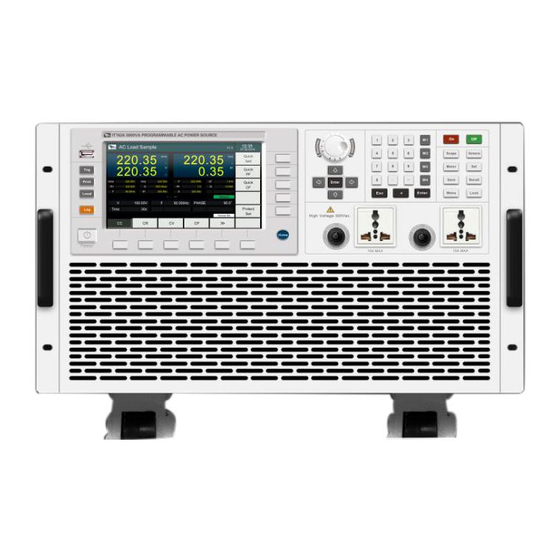
2.2 Front Panel Introduction Different models of IT7600 Series power supply have different front panels. The front panel of IT7626/IT7627/IT7628 is as shown below. IT7622/IT7624 model has same front panel as IT7626/IT7627/IT7628 model except over-current protection output terminal and output terminals. -
Page 23: Key Introduction
17 Output terminals 18 Left and right handle 2.3 Key introduction The key functions of the front panel and the keys in the key zones of IT7600 series are shown in the following figure. Copyright ©ITECH Electronic Co., Ltd. - Page 24 Up/Down key and Left/Right key List Edit: those lines which are not displayed can be displayed by operating the Left/Right key. Those rows which are not displayed can be displayed by operating the Up/Down key. Copyright ©ITECH Electronic Co., Ltd.
- Page 25 Harmonic Measurement key When this key is pressed, the harmonic measurement results and the menu of /Harmonic harmonic measurement parameter configuration will be displayed. Vector key When this key is pressed,the vector graph to /Vector current measurement data will be displayed. Copyright ©ITECH Electronic Co., Ltd.
-
Page 26: Introduction To Information On The Interface
THDWave: THD wave 2.5 Introduction to Interface Symbols The interface of IT7600 power supply will display the following symbols. All the symbols and description are listed in the table below. Char Function description Char Function description Copyright ©ITECH Electronic Co., Ltd. -
Page 27: Rear Panel Introduction
Function RMS OCP Three phase mode Paralle mode PEAK OCP 2.6 Rear Panel Introduction Rear panel of IT7622/IT7624 1 System bus 2 CLK_IN, clock input 3 CLK_OUT, clock output 4 External simulation control terminal 5 GPIB communication interface 6 LAN communication interface... -
Page 28: Power-On Selftest
13 Cooling fans 2.7 Power-on Selftest A successful selftest indicates that the purchased power product meets delivery standards and is available for normal usage. Before operation, please confirm that you have fully understood the safety instructions. Copyright ©ITECH Electronic Co., Ltd. - Page 29 The power supply will do selftest. After initialization, the LCD screen displays the following information. NOTE In case of any error, self-test will stop. Contact ITECH distributors or technical service engineer. AC sourece Press [Shift]+[Setup] (Menu),and the LCD screen of the displays the system information.
- Page 30 LCD has passed self-test. Press key Up/Down to select Key Test. Press [Enter]. Operate according to tips on the screen. Press [Esc]. If ‘Key Checking Finsh’ displays on the screen, Key has passed self-test. Copyright ©ITECH Electronic Co., Ltd.
- Page 31 Check whether the fuse of power supply is burned out. If yes, replace with a fuse of the same specification. The fuse of IT7622/IT7624 is arranged on the internal circuit board of the machine, and must be replaced by professional personnel. ...
-
Page 32: Chapter3 Basic Operations
AC: AC voltage value. Setting range is different among Auto, High and Low range. Refer to 9.1 Main technical parameters for more details. Frequency with range of 10-5KHz. Freq: Start: Start phase angle Stop: Stop phase angle Copyright ©ITECH Electronic Co., Ltd. -
Page 33: Dc Output Mode
If user set ACDC Mode, the instrument will simulate AC and DC power supply, which can add DC component to AC voltage. Set the output voltage in the main interface, as shown in the figure below. Copyright ©ITECH Electronic Co., Ltd. -
Page 34: Switching Output Range
Sweep function is not applicable under DC mode and ACDC mode. Operating steps Press [Shift]+[List] (Step) on the front panel to enter the sweep interface, as shown in the figure below. Copyright ©ITECH Electronic Co., Ltd. -
Page 35: Key Lock Function
Press [Shift]+[Enter] (Lock) button to set the key lock state.If keyboard has been locked,the indicator light ”Lock” will display on the LCD.In addition,when keyboard are locked,all buttons can’t be used except Local key Press [Shift]+[Enter] (Lock) once again will relieve key lock function. Copyright ©ITECH Electronic Co., Ltd. -
Page 36: Switching Local/Remote Mode
Slow:Slow speed System Setup Fast: fast speed Control the loop stability. If the capacitive or inductive load is connected, select “Slow”. If the resistive load is connected, select “Fast”. External simulation test: Ext-Ctrl Copyright ©ITECH Electronic Co., Ltd. - Page 37 Prescaler: set the Prescale Bit Segment1: range from 0~16. range from Bit Segment2: 0~8. Can ID: set Can address. Other1-4 ID: set other Can address. Transformer Setup Transformer Transformer accessory Configure Transformer Function function: Copyright ©ITECH Electronic Co., Ltd.
- Page 38 This item can isolate or connect the user loop. When Close is selected, the relay is closed, and the user circuit can be connected; if Open is selected, the relay is open, and the user circuit is isolated. Copyright ©ITECH Electronic Co., Ltd.
-
Page 39: Configuration Save/Recall Function
Setting of protection function Press [Shift]+[Setup] (Menu) key to enter. Press [Protect Configure] in the interface to enter the “Current Protect” interface, where you can set the following protection. Protection Upper Limit Immediate Delay Time Type protection Copyright ©ITECH Electronic Co., Ltd. - Page 40 In the case of overcurrent protection, disconnect the tested object at first. Press [shift]+[M4] on the front panel (or send the command “PROTection:CLEar”) to clear on the front panel and exit the Rms OCP mode. Copyright ©ITECH Electronic Co., Ltd.
-
Page 41: Data Recording Function
IT7600 series has four t source to choose: rigger trigger by keys (Key),Software trigger (Software),Bus trigger (Bus) and External signal trigger (External). Key: if [Trig] on the front panel is pressed in the valid key trigger mode, the Copyright ©ITECH Electronic Co., Ltd. -
Page 42: External Simulation Test Function
If the tested instrument consumes large current, a large voltage drop will be detected in connection line between tested instrument and power supply terminal. To ensure measurement accuracy, a remote sense measurement terminal is provided at power supply rear panel to compensate voltage drop lost in wire. Copyright ©ITECH Electronic Co., Ltd. -
Page 43: Three-Phase Parallel Setup
Y-type and Δ-type connection according to the actual requirements. Flexible connection can meet various test requirements. Under Parallel mode, the output power cannot exceed 90% of the total power to avoid loss caused by AC power unbalance. Copyright ©ITECH Electronic Co., Ltd. - Page 44 ООО "Техэнком" Контрольно-измерительные приборы и оборудование www.tehencom.com Basic Operations Connections of three-phase parallel power supplies include Y-type and Δ-type connection, as shown in the following figures(take the example of IT7626) Y type connection Copyright ©ITECH Electronic Co., Ltd.
- Page 45 Select one connection method as shown above. After wiring, configure relevant parameters of the functions of the three-phase AC power supply.Detailed operation steps are shown below: Copyright ©ITECH Electronic Co., Ltd.
- Page 46 Unbalance mode, and set voltage values, frequency values, start angles and end angles of the three phases. Press soft key [More Setting] to set the angle difference of the three phases. As shown below. Copyright ©ITECH Electronic Co., Ltd.
- Page 47 Set the angle difference between Phase B and A. C->A Set the angle difference between Phase C and A. After setting the parameters, press [On] on the front panel. Relevant values will be displayed on LCD. Copyright ©ITECH Electronic Co., Ltd.
-
Page 48: Chapter4 Measurement Functions
Disp: metering display interface Conf: metering parameter configuration interface 4.2 Setup interface Press [Meter] on the lower part of the screen, and then press [Conf] to enter the metering parameter configuration interface, as shown in the figure below. Copyright ©ITECH Electronic Co., Ltd. - Page 49 Positive current value [A] peak value [A] Crest factor Power factor Ipeak Peak current value Apparent power Reactive power Ptot Total power DC voltage DC current Positive voltage Negative voltage peak peak value value Copyright ©ITECH Electronic Co., Ltd.
-
Page 50: Chapter5 Oscilloscope Functions
Waveform display / display Trig Setup Trigger setting. Phase Phase selection, with four options: A, B, C and ALL. The default is Phase A in the standalone mode. You can switch the four options under three-phase mode. Copyright ©ITECH Electronic Co., Ltd. - Page 51 Stop status. Introduction to waveform display interface Voltage grid Trigger delay Time grid Trigger state The voltage difference between Measuring Trigger level Wave ground level and point parameters of center vertical Copyright ©ITECH Electronic Co., Ltd.
- Page 52 It is divided into the Auto mode and Normal mode. In the Auto mode, the displayed waveform will be updated when triggering occurs in the suspension time; otherwise, the displayed waveform will be updated automatically. Copyright ©ITECH Electronic Co., Ltd.
-
Page 53: Adjustment Of Measuring Parameters
The detailed operation steps are as follows: Operation steps Press [Scope] to enter into the scope interface. Press [Measure] and select [Meter]. Press soft keys on the front panel to select the measuring parameters you need. Copyright ©ITECH Electronic Co., Ltd. -
Page 54: Setting Of Trigger Configuration
Trigger source : select the voltage or current as the trigger source. Mode Trigger mode : select the Auto, Normal or single mode. Slope Trigger slope : select the rising edge, falling edge or rising/falling. Copyright ©ITECH Electronic Co., Ltd. -
Page 55: Chapter6 Harmonic Function
Thd Formula Distortion factor calculation formula. %r: displaying harmonics in the form of percentage to the overall voltage amplitude of all harmonics. %f: displaying harmonics in the form of percentage to the fundamental voltage. Copyright ©ITECH Electronic Co., Ltd. - Page 56 Phase A, and displays 0 for the other two phases, as shown in the figure below; under three-phase mode, display effective values for the three phases. Copyright ©ITECH Electronic Co., Ltd.
-
Page 57: Distortion Factor Calculation Formula
LIST. You can press the Up and Down key to display the hidden rows, i.e. hidden data of single harmonic data. 6.2 Distortion factor calculation formula The following two formulas can be selected for calculation of the distortion Copyright ©ITECH Electronic Co., Ltd. - Page 58 ∑ ∑ distortion rate current Total NOTE ∑ ∑ Total Total , Total harmonics are calculated as follows: indicates the harmonic order, and max indicates the upper limit of analysis orders. 50 orders at most. Copyright ©ITECH Electronic Co., Ltd.
-
Page 59: Chapter7 Vector Function
% r: displaying harmonics in the form of percentage to the overall current (or voltage power) amplitude of all harmonics. % f: displaying harmonics in the form of percentage to the fundamental current (or voltage power). Copyright ©ITECH Electronic Co., Ltd. - Page 60 The vector function is valid only in the three-phase mode. The phase parameters in the figure correspond to those in the harmonic function. The vector diagram is another kind of demonstration of parameters in the harmonic function. Copyright ©ITECH Electronic Co., Ltd.
-
Page 61: Chapter8 Configuration Of Any Waveform
Soft Key of Description Menu Create a new List file. Create New Edit the saved List file. Edit Current Recall the saved List file. Recall Config Export Config Export list file Delete Config Delete list file Copyright ©ITECH Electronic Co., Ltd. - Page 62 Parameters of the List editing zone are as follows: Parameter Explain Run Jump Edit the starting steps of the List file. Copyright ©ITECH Electronic Co., Ltd.
- Page 63 : run next step after the set Time. TIME : run next step after receiving the trigger signal. TRIG Press [Insert] to insert a single step. The single step will automatically appear in the List. After configuration, the following interface will appear. Copyright ©ITECH Electronic Co., Ltd.
- Page 64 [Shift]+[Recall] (Save) on the front panel to save the file in the name “List01 csv” (example).Press [Enter] to confirm. Press [Esc] to go back to the previous interface. The configured “List01 csv” file will appear in the interface, as shown by the red box below. Copyright ©ITECH Electronic Co., Ltd.
- Page 65 After configuring, go back to the List interface. Parameters with inconsistent three-phase are marked with a “*” at front, as shown in the red box above. The list only displays A-phase parameters. Copyright ©ITECH Electronic Co., Ltd.
- Page 66 Press [List] on the front panel to enter the List function configuration interface, select soft key [standard]. Press [Edit Current] to enter the saved List01 csv file. Edit the saved List02 csv file, as shown in the figure below. Copyright ©ITECH Electronic Co., Ltd.
- Page 67 USB disk. List import file formats under single-phase mode: List import file formats under three-phase mode: (The three same No. values correspond to A/B/C phase parameters of this step). Copyright ©ITECH Electronic Co., Ltd.
- Page 68 Insert the USB disk into the USB interface of the front panel. Press [List] on the front panel to enter the List function configuration interface. Press [Recall Config]. Select the List02 csv file and open it. The List file will be imported, as shown in the figure below. Copyright ©ITECH Electronic Co., Ltd.
- Page 69 Press [List] on the front panel to enter the List function configuration interface. Press [Export Config]. Select the saved List02 csv file, press [Enter] to confirm. This file will be exported into the USB disk. Copyright ©ITECH Electronic Co., Ltd.
-
Page 70: Setting Of Surge/Trapped Configuration
DUT under this circumstance. Operating steps Press [List] on the front panel to enter the List function configuration interface. Press [Surge-Trap] in the List interface to enter the surge/trap parameter setup interface, as shown in the figure below. Copyright ©ITECH Electronic Co., Ltd. - Page 71 Off: run the set surge/trap based on the time. On: run the set surge/trap after receiving the trigger signal. After setting the parameters, press [On] on the front panel. Then press [Scope], and the following waveform interface will appear Copyright ©ITECH Electronic Co., Ltd.
-
Page 72: Self-Defined Waveform Function
Press [List] on the front panel, and enter the [Self-defined Wave Edit] interface to configure the waveform, as shown in the figure below. Recall: recall the saved waveform file. Save/Exit: save and edit the waveform file. Export: export the waveform file. Copyright ©ITECH Electronic Co., Ltd. - Page 73 List function configuration interface. Press soft key [Self-defined Wave Edit]. 5. Press soft key [Recall]. Select the harWave csv file. Press [Enter] for confirmation. This List file will be imported. As shown below. Copyright ©ITECH Electronic Co., Ltd.
-
Page 74: Thd Wave
The distorted waveform can simulate voltage harmonic wave in the circuit. The user can set the extent to which the output voltage waveform deviates from the Sin wave voltage and test the usage of the DUT under this circumstance. Copyright ©ITECH Electronic Co., Ltd. - Page 75 Prev View the previous THD parameter. Delete Delete the THD parameter. Set the harmonic distortion waveform, and press [Enter]. The set parameter will be displayed in the right zone, as shown in the figure below. Copyright ©ITECH Electronic Co., Ltd.
- Page 76 ООО "Техэнком" Контрольно-измерительные приборы и оборудование www.tehencom.com List Function Then press [Shift]+[Recall] (Save) on the front panel to save this parameter. Copyright ©ITECH Electronic Co., Ltd.
-
Page 77: Chapter9 Technical Specifications
≤0.5% at 10-500Hz (Resistive Load) Total Harmonic Distortion(T.H.D) ≤2% at 501-5000Hz (Resistive Load) Crest Factor ≤0.1%FS(Resistive Load) Line Regulation ≤0.5%FS(Resistive Load) Load Regulation ≤100us(typical) Response Time single phase Output phase DC Output 375W Max.output power Copyright ©ITECH Electronic Co., Ltd. - Page 78 AC Current(peak) ±0.3%+(0.3%+0.2%×Kfreq)×FS Accuracy Temp. ±(0.04% per degree from 25℃) coefficient 10mW Range ±0.4%+(0.4%+0.2%×Kfreq)×FS Accuracy Power Temp. ±(0.04% per degree from 25℃) coefficient 0-360° Range 1° Phase Angle Resolution ±1°(45-65Hz) Accuracy 10HZ-5KHz Range Frequency 0.1Hz Resolution Copyright ©ITECH Electronic Co., Ltd.
- Page 79 Frequency 30A/60A Max.Current 0.7(typical) Power Factor AC Output 1.5KVA Max.output power Voltage range 2V-300V, 1V-150V/2V-300V Auto 10mV Voltage resolution ±0.2%+(0.2%+0.2%×Kfreq)×FS Voltage accuracy Temp. coefficient ±(0.04% per degree from 25°C) 1-150Vac 0-12Arms Max Current(rms) 2-300Vac 0-6Arms Copyright ©ITECH Electronic Co., Ltd.
- Page 80 0-300Vac Range 10mV Resolution AC Voltage ±(0.2%+0.2%FS) Accuracy Temp. ±(0.04% per degree from 25°C) coefficient 0-12Arms Range Resolution 10mA Current(rms) ±0.3%+(0.3%+0.2%×Kfreq)×FS Accuracy Temp. ±(0.04% per degree from 25°C) coefficient 0-36Apeak Range AC Current(peak) Resolution 10mA Copyright ©ITECH Electronic Co., Ltd.
- Page 81 : Testing premise is in Fast mode : The minimum voltage setting must not be less than 50Vdc. : FS=full: Vdc=424Vdc; Idc=6A; P=750W. Parameter IT7626 V1.6 AC Input 220Vac±10% Voltage Phase single phase 10-5kHz Frequency Copyright ©ITECH Electronic Co., Ltd.
- Page 82 Voltage r esolution Voltage output and readback ±(0.2%+0.2%FS) Accuracy Temp. coefficient ±(0.04% per degree from 25°C) 12A/6A Current range 10mA Current r esolution Current readback accuracy ±(0.3%+0.3%FS) Power meter accuracy ±(0.4%+0.4%FS) Peak 300mVp-p Voltage ripple 150mVrms Copyright ©ITECH Electronic Co., Ltd.
- Page 83 Resolution Accuracy ±0.1%+0.1Hz(45Hz-999.9Hz)/±0.1%+1Hz(1KHz-5KHz) Other Protection OVP, OPP, OCP, OTP Interface GPIB, USB, LAN, RS232, CAN 10 groups Memory (WxHxD) Dimension 100Kg Weight Preconditions for voltage accuracy : Slow loop speed: 10-100Hz; Fast loop speed: 10-5KHz. Copyright ©ITECH Electronic Co., Ltd.
- Page 84 ±(0.04% per degree from 25°C) 72A/36A Max.Current (1φ) Peak(CF=3) 216A/108A 24A/12A Max.Current (3φ) Peak(CF=3) 72A/36A ≤0.5% at 10-500Hz (Resistive Load) Total Harmonic Distortion(T.H.D) ≤2% at 501-5000Hz (Resistive Load) Crest Factor ≤0.1%FS(Resistive Load) Line Regulation ≤0.5%FS(Resistive Load) Load Regulation Copyright ©ITECH Electronic Co., Ltd.
- Page 85 ±(0.04% per degree from 25°C) coefficient Range 0-216Apeak 10mA Resolution Current(peak) ±0.3%+(0.3%+0.2%×Kfreq)×FS Accuracy Temp. ±(0.04% per degree from 25°C) coefficient 10mW Resolution ±0.4%+(0.4%+0.2%×Kfreq)×FS Accuracy Power Temp. ±(0.04% per degree from 25°C) coefficient Phase Angle Range 0-360° Copyright ©ITECH Electronic Co., Ltd.
- Page 86 : The maximum current range is 90% in the parallel mode. Parameter IT7628 V1.4 AC Input 380Vac±10%(Y) Voltage 3φ Phase 10-5kHz Frequency 120A Max.Current 0.7(typical) Power Factor AC Output 1φ or 3φ Output phase 18KVA Max.output power Copyright ©ITECH Electronic Co., Ltd.
- Page 87 Temp. coefficient ±(0.04% per degree from 25°C) Current range 72A/36A 10mA Current r esolution ±(0.3%+0.3%FS) Current readback accuracy ±(0.4%+0.4%FS) Power meter accuracy Peak 600mVp-p Voltage ripple 300mVrms Meter 0-300Vac Range 10mV AC Voltage Resolution Accuracy ±(0.2%+0.2%FS) Copyright ©ITECH Electronic Co., Ltd.
- Page 88 The maximum distortion test is carried out by outputting the maximum current to linear load under 125Vac (Auto mode) and 250Vac (300V mode). : The test frequency accuracy should ensure that the minimum voltage is 30Vac. : The test mode is Fast. Copyright ©ITECH Electronic Co., Ltd.
-
Page 89: Supplemental Characteristics
: FS corresponds to the full range: Vdc=400Vdc;Idc=72A;P=9000W; : The maximum current range is 90% in the parallel mode. 9.2 Supplemental characteristics State storage capacity 10sets Recommended calibration frequency once a year Cooling style fans Copyright ©ITECH Electronic Co., Ltd. -
Page 90: Chapter10 Remote Control
DB-25 plug (one end) and DB-9 plug (the other end) are required (not the modulating cable of the air-conditioner) description connectionless TXD,transmit data RXD,receive data connectionless GND, ground connectionless RS-232 plug pins CTS, clear transfer RTS, ready transfer connectionless Copyright ©ITECH Electronic Co., Ltd. -
Page 91: Usb Interface
TRIGGER command to the function layer The functions of power supply’s USB488 are as follows: receive all SCPI commands device is SR1 enabled device is RL1 enabled device is DT1 enabled Copyright ©ITECH Electronic Co., Ltd. -
Page 92: Lan Interface
Pin No. Description CAN interface pin CANH CANL CAN Troubleshooting: If CAN connection fails, check that: The PC and power supply have same Baud rate. Appropriate interface pin or adapter is used, as described in CAN Copyright ©ITECH Electronic Co., Ltd. - Page 93 Calculate the Baud Rate according to the above three parameters. ID (Can ID): Set Can Port ID based on computer. IDs of other necessary ports (Other1-4 ID): Set IDs of other Can ports as needed. Copyright ©ITECH Electronic Co., Ltd.
-
Page 94: Appendix
Appendix Specifications of Red and Black Test Lines ITECH provides you with optional red and black test lines, the user can choose the company's test line for testing. For specifications of ITECH test lines and maximum current values, refer to the table below. - Page 95 Контрольно-измерительные приборы и оборудование www.tehencom.com Contact US Thank you for purchasing ITECH products. If you have any doubt about this product, please contact us as follow. 1. Please refer to the CD-ROM of related user’s manual in package. 2. Visit ITECH website www.itechate.com...
Need help?
Do you have a question about the IT7622 and is the answer not in the manual?
Questions and answers