
Related Manuals for ITech IT7900 Series


Summary of Contents for ITech IT7900 Series
- Page 1 Programmable AC Power Supply IT7900 Series User Manual Model: IT7900 Version: V1.0/2021.06...
- Page 2 Notices Warranty Safety Notices © Itech Electronic, Co., Ltd. 2021 The materials contained in this No part of this manual may be document are provided “as is”, and reproduced in any form or by any is subject to change, without prior means ( including electronic storage notice, in future editions.
-
Page 3: Warranty
IT7900 User Manual Quality Certification and Assurance We certify that IT7900 series power supply meets all the published specifications at time of shipment from the factory. Warranty ITECH warrants that the product will be free from defects in material and workmanship under normal use for a period of one ( 1) year from the date of delivery ( except those described in the Limitation of Warranty below). - Page 4 Failure to comply with these precautions or specific warnings elsewhere in this manual will constitute a default under safety standards of design, manufacture and intended use of the instrument. ITECH assumes no liability for the customer’s failure to comply with these precautions.
-
Page 5: Environmental Conditions
( if any) affixed refers to the year when the design was approved. The instrument complies with the WEEE Directive 2002/96/EC) marking requirement. This affix product label indicates that you must not discard the electrical/electronic product in domestic household waste. Copyright ©ITECH Electronic Co., Ltd. -
Page 6: Waste Electrical And Electronic Equipment ( Weee) Directive
With reference to the equipment classifications described in the Annex 1 of the WEEE Directive, this instrument is classified as a “Monitoring and Control Instrument”. To return this unwanted instrument, contact your nearest ITECH office. Copyright ©ITECH Electronic Co., Ltd. -
Page 7: Compliance Information
2. Connection of the instrument to a test object may produce radiations beyond the specified limit. 3. Use high-performance shielded interface cable to ensure conformity with the EMC standards listed above. Safety Standard IEC 61010-1:2010/ EN 61010-1:2010 Copyright ©ITECH Electronic Co., Ltd. -
Page 8: Table Of Contents
6.1 System Menu Reference ............................ 40 5.1.1 Menu function ............................. 44 5.1.2 Set the communication interface ........................ 45 5.1.3 View the System Information ........................45 6.2 Key Lock Function ............................... 45 6.3 Switching Local/Remote Mode .......................... 45 Copyright ©ITECH Electronic Co., Ltd. - Page 9 10.4 GPIB Interface (Optional) ..........................75 10.5 RS–232 Interface (Optional) ..........................76 10.6 Commonly Used Commands Overview ......................77 10.7 Demo Software Introduction ........................... 78 Appendix ................................79 Specifications of Red and Black Test Lines ....................... 79 Copyright ©ITECH Electronic Co., Ltd.
-
Page 10: Chapter1 Overview
Chapter1 Overview This chapter introduces the front panel, the rear panel, key functions and LCD display function of the IT7900 series power supply, make sure that you can quickly know the appearance, instruction and the key function before you operate the power supply. Help you make better use of this series of power supply. -
Page 11: Models And Options
IT7945-350-270 45kVA 350V 270A 1Φ or 3Φ IT7960-350-360 60kVA 350V 360A 1Φ or 3Φ IT7975-350-450 75kVA 350V 450A 1Φ or 3Φ IT7990-350-540 90kVA 350V 540A 1Φ or 3Φ IT79105-350-630 105kVA 350V 630A 1Φ or 3Φ Copyright ©ITECH Electronic Co., Ltd. -
Page 12: Optional Accessories
The IT7900 series supports the following optional accessories (sold separately), the details are as below: The interface expansion slot provided on the rear panel of the IT7900 series instrument allows users to flexibly expand according to their needs. Different interface cards can be selected to achieve different functions. -
Page 13: Instrument Size Introduction
Overview 1.4 Instrument Size Introduction The instrument should be installed at well-ventilated and rational-sized space. Please select appropriate space for installation based on the power supply size. IT7915-350-90 model Copyright ©ITECH Electronic Co., Ltd. -
Page 14: Chapter2 Instrument Introduction
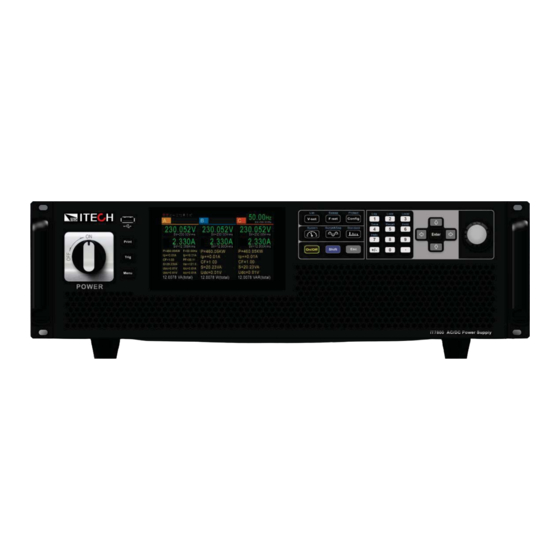
The front panel of IT7900 is as shown below. 1 Power Switch 2 USB interface /Print/Trig/Menu 3 LCD touch screen 4 Function key 5 Number key 6 Up, down, left and right key and enter key 7 Rotary knob 8 Vent hole Copyright ©ITECH Electronic Co., Ltd. -
Page 15: Keyboard
Instrument Introduction 2.3 Keyboard The keyboard introduction of IT7900 series Power Supply is shown as follows. Keys Description Print Used for saving screen images Trig Used for manual trigger Power Power Switch Menu Used for going back to menu page... -
Page 16: Push-On Knob
[Shift]+ [7] (Help) Obtain the help information. 2.4 Push-on Knob The IT7900 series Power Supply provides a knob on the front panel as shown in the next figure. The functions of the posh-on knob is described as follows. Adjust the value setting... -
Page 17: Rear Panel
After completing the value setting or selecting a menu item, pushing the knob acts like pressing [Enter] key to confirm the operation. 2.5 Rear Panel The rear panel of the IT7900 series 3U model is shown below. Name Description ground terminal Ground screw for making chassis ground connections. - Page 18 USB interface USB communication interface. system bus Used for communication between instruments in parallel operation feature. AC power input Used to connect AC power to start instrument. socket Copyright ©ITECH Electronic Co., Ltd.
-
Page 19: Chapter3 Installation
Connecting the power cord The standard power cord specifications for this series of 3U instruments are divided into the following types according to different regions: Copyright ©ITECH Electronic Co., Ltd. - Page 20 AC distribution box (the rated AC current on L3 is 0, so, it can be connected or not). In case multiple units are connected to the same main AC distribution box. It is recommended to follow the suggestion connection diagram as below. Single phase input connecting: Copyright ©ITECH Electronic Co., Ltd.
- Page 21 L1, L2 and L3 terminals one by one. b) The yellow-green wire is grounding wire, which is connected to the Copyright ©ITECH Electronic Co., Ltd.
-
Page 22: Connecting Test Lines ( Optional)
Always use test lines provided by ITECH to connect the equipment. If test lines from other factories are used, please check that the test line can withstand maximum current. - Page 23 The connection diagram of single phase is shown as follow: NOTE When the output voltage has DC voltage, the output terminal L is positive, and N is negative. The connection diagram of three phase is shown as follow: Copyright ©ITECH Electronic Co., Ltd.
- Page 24 1,200A, then 4 pieces of 360A red and black cables are required. 4. Thread the red and black test cables through the output terminals cover of the power system and install the cover. Copyright ©ITECH Electronic Co., Ltd.
- Page 25 The connection diagram and steps of remote measurement are as follows: The connection diagram of single phase is shown as follow: NOTE When the output voltage has DC voltage, the output terminal L is positive, and N is negative. Copyright ©ITECH Electronic Co., Ltd.
- Page 26 For example, the maximum current is 1,200A, then 4 pieces of 360A red and black cables are required. 4. Thread the red and black test cables through the output terminals cover of Copyright ©ITECH Electronic Co., Ltd.
- Page 27 7. Connect the other end of the red and black cables to the DUT. The positive and negative poles must be properly connected and fastened when wiring. 8. Power on the instrument and turn on the Sense function of the instrument. Copyright ©ITECH Electronic Co., Ltd.
-
Page 28: Chapter4 Getting Started
The disconnect device must be close to the equipment, be easily accessible, and be marked as the disconnect device for this equipment. Copyright ©ITECH Electronic Co., Ltd. -
Page 29: Home-Screen Overview
User can adjust the power switch directly to turn on or turn off the instrument. The status of Power switch is as follows. The switching knob of the IT7900 series power supply allows the user to turn the power on by 90° clockwise or to turn the power off by 90° counterclockwise. - Page 30 Getting Started Single Phase Mode The meter interface of IT7900 series power supply is shown as follow. Status bar Voltage setting&meter value Frequency setting&meter value Display area of measuring data Three Phase Mode The meter interface of IT7900 three phase mode is shown as follow.
- Page 31 The AC source is in Surge&Sag function remote mode indicator External Simulation Test Record log Function LIST is running LIST is finished LIST function is waiting for Sweep function is trigger waiting for trigger Copyright ©ITECH Electronic Co., Ltd.
-
Page 32: Touch Screen Introduction
This provides convenience for the user to set. The knob can Copyright ©ITECH Electronic Co., Ltd. -
Page 33: Output On/Off Control
The VFD displays the meter value such as voltage, current, power and so on. If the [On/Off] key light is off, indicates that the output is turned off. The VFD displays that the power supply state is OFF. Copyright ©ITECH Electronic Co., Ltd. -
Page 34: Chapter5 Operation And Application
5.1 full 4-Quadrant output character The IT7900 series represent the newest generation of programmable, full four- quadrant grid simulators with full 100% of current rating in both source and sink mode, and provides energy recovery capability. The power generated by the DUT during the test can be easily retuned to the AC grid, rather than being dissipated as heat. -
Page 35: Select The Output Mode
DUTs test independently. The output mode can be set to AC/DC/ACDC/DCAC. 5.3 Select the Output Mode The IT7900 series has four output modes: AC, DC, AC+DC, DC+AC. It not only provides pure AC/DC output, but also can use AC+DC and DC+AC output modes to realize "AC output plus DC bias"... -
Page 36: Dc Output Mode
If the output mode select to AC+DC Mode, the instrument will simulate AC and DC power supply, which can add DC component to AC voltage. Set the output voltage in the main interface, as shown in the figure below. Copyright ©ITECH Electronic Co., Ltd. -
Page 37: Dc+Ac Mode
If the output mode select to DC+AC Mode, the instrument will simulate DC and AC power supply, which can add AC component to DC voltage. Set the output voltage in the main interface, as shown in the figure below. Copyright ©ITECH Electronic Co., Ltd. -
Page 38: Cv Mode/Cc Mode And Cp Mode
The Vac setting range is 10% of rated voltage. 5.4 CV Mode/CC Mode and CP Mode The IT7900 series power supply is constant voltage CV output mode by default. Constant current CC and constant power CP modes can also be supported. -
Page 39: Waveform Selection
Operation and Application 5.6 Waveform Selection The user can set the output waveform in the config menu of IT7900 series power supply. Eight output waveforms below are available, user can select the waveform in Config->Waveform menu. Sine Square Sawtooth Triangle... -
Page 40: Programmable Output Impedance
Sweep function is not applicable under DC mode and ACDC mode. Operating steps Press [Shift] + [F-set](Sweep)on the front panel to enter the sweep interface, as shown in the figure below. Copyright ©ITECH Electronic Co., Ltd. - Page 41 [Meter] to observe the output parameters in the main interface. After sweeping, [On/Off] on the front panel will be off, and [Idle] status will be displayed on LCD. You can press [Stop] on the Sweep interface to stop the Sweep function. Copyright ©ITECH Electronic Co., Ltd.
-
Page 42: Chapter6 System-Related Functions
I/O input signal: 0-360° Freq limit+ Set the frequency upper limit. Freq limit- Set the frequency lower limit. Set the output mode when the frequency lock fails: Exception Stop: stop output Setting-freq: Output according to the set frequency. Copyright ©ITECH Electronic Co., Ltd. - Page 43 Last-OFF the same settings as last time you turned off the instrument, but the [On/Off] is OFF state. Parallel mode Set the instruments to parallel operation mode. Parallel Master: Set the instrument to Copyright ©ITECH Electronic Co., Ltd.
- Page 44 IT-E177 communication board into expansion slot, the menu displays this information. Baud rate Baud rate Databits Data bit: 5/6/7/8 Stopbits Stop bit: 1/2 Parity bit: N (No parity) / E (Even Even-odd check parity) / O Copyright ©ITECH Electronic Co., Ltd.
- Page 45 Function setting of pin 7 Reverse On/Off Trig2-in Tig2-out Function Input Output Product model Display the instrument model. Serial number Display the serial number. Information Software version Display the control board version. MAC address MAC address Copyright ©ITECH Electronic Co., Ltd.
-
Page 46: Menu Function
2. Press the Up/Down key or turn the knob to select the Touch screen lock and press [Enter]. On: enable the touch screen Off: disable the touch screen Set the Loop Speed This item can control stability of the loop. When the connected load is capacitive Copyright ©ITECH Electronic Co., Ltd. -
Page 47: Set The Communication Interface
5.1.2 Set the communication interface This menu item is used to set the communication information between instrument and PC. The standard communication interfaces for IT7900 series power supply are USB, LAN and CAN. You can also select the non-standard interface GPIB or RS-232 based on personal requirement. -
Page 48: Save And Recall Operations
Press [Enter] to recall the parameters. 6.5 Protection Function IT7900 series source includes the following protection functions: overcurrent protection (Current RMS protection, Current peak protection), voltage limit protection and over-temperature protection (OTP). -
Page 49: Current Rms Protection
(rms) will turn off the output. How to Set Press [Shift]+[Config] (Protect) keys and enter to Protection menu. Press the up/down key or rotate the knob to select Current RMS protection and press [Enter]. Copyright ©ITECH Electronic Co., Ltd. -
Page 50: Set The Current Peak Protection
Take the voltage limit setting for an example, the operating as follows: Press [Shift]+[Config] (Protect) keys and enter to Protection menu. Press the up/down key or rotate the knob to select Voltage limit range and press [Enter]. Copyright ©ITECH Electronic Co., Ltd. -
Page 51: Over-Temperature Protection (Otp)
OPP mode. 6.6 Screen Capture Function IT7900 series power supply has the screen capture function. Insert the USB equipment into the USB interface of the front panel, and press [Print] on the front panel to capture and save the current screen into the USB disk. - Page 52 3. Connect the AC input terminals of the three units separately, and connect them to the AC distribution box. 4. Connect the output terminals of the three units in parallel and connect them to the DUT. Copyright ©ITECH Electronic Co., Ltd.
- Page 53 1. Set each of the three instruments to single mode. 2. Press the composite keys [Shift]+ (System) on the front panel to enter the system menu. 3. Select General menu. 4. Set the Parallel Mode, set them to single. Copyright ©ITECH Electronic Co., Ltd.
-
Page 54: Remote Measurement Function
After the instrument is restarted, the screen shows that the instrument is working in single mode. 6.9 Remote Measurement Function The IT7900 series power supply supports two connection methods: Local measurement and Remote sensing. The remote sensing is used for maximizing measurement accuracy. (Refer to 2.4 Connecting Test Lines). - Page 55 The IO-1 ~ IO-7 pins are featured default function, the user can setting the I/O function according to requirement. The Input and Output are the general digital I/O function, and the settings and functions of the seven pins are the Copyright ©ITECH Electronic Co., Ltd.
- Page 56 IO-2. Digital IO-3 IO-3 Input Output The default function is protection state indicator. IO-3 pin will output high or low level based on whether the instrument is under protection or not. Under normal Copyright ©ITECH Electronic Co., Ltd.
-
Page 57: Analogue Function (Ext-Program) (Optional)
6.11 Analogue Function (Ext-Program) (Optional) The interface expansion slot provided on the rear panel of the IT7900 series. This function is not standard with the instrument and is optional for users. When the interface card selected by the user is RS232+Analog interface (IT- E177), the analog interface can realize the external analog function. - Page 58 For the detailed function definition of the pin, please refer to the definition of the analog pins description. The following is an example of amplitude modulation to introduce Copyright ©ITECH Electronic Co., Ltd.
- Page 59 . Under single phase mode, the phase cannot be set, under three phase mode, the voltage and current of phase can be set in menu. The wiring diagram is shown in the figure below. Copyright ©ITECH Electronic Co., Ltd.
-
Page 60: Chapter7 Measurement Functions
This chapter describes the characteristics and operations of the basic metering function of IT7900 series source. IT7900 series source has rich functions of basic metering of electric energy and can accurately measure the parameters such as Vrms, Irms, Ipeak, Idc, CF, PF. -
Page 61: Oscilloscope Mode
Negative voltage peak value 7.2 Oscilloscope Mode IT7900 series source has the function of displaying the waveform based on sampling data. The user can select to display or hide the voltage and current waveform of the input unit. Only the necessary waveform is displayed, which can facilitate observation. -
Page 62: Harmonic Measurement
Display trigger source edge Settings, parameters are: rising edge, falling edge, rising and falling edge, pulse. 7.3 Harmonic measurement IT7900 series source can display harmonic parameters in the list or bar chart form to make the analysis of test result clear. Press key on the front panel, and the following initial interface of harmonic measurement will appear. - Page 63 LIST. You can press the Up and Down key to display the hidden rows, i.e. hidden data of single harmonic data. Introduction to vector interface When vector mode is selected in the harmonic measurement mode, to enter the vector measurement interface, as shown in the figure below. Copyright ©ITECH Electronic Co., Ltd.
-
Page 64: Chapter8 Configuration Arbitrary Waveform
Open: Select the List file to execute from local memory or USB disk. New: Create a new List file. Delete: delete the present List file. Press [New] and enter to the List file edit interface. Copyright ©ITECH Electronic Co., Ltd. - Page 65 Click on screen to set the ACrms, Freq and Time, if need to set other parameters such as phase control or step running control, you can click More to enter the advanced menu. List parameter description Parameter Description Voltage AC Step1 voltage amplitude and slew rate. Copyright ©ITECH Electronic Co., Ltd.
-
Page 66: Select/Run List File
Press [Run] in the list function interface. Running indicator will appear in interface. Press [Scope] key to view the output waveform. 8.1.3 Set trigger source IT7900 series has four t source to choose: rigger trigger by keys (Manual), Bus trigger (Bus) and External signal trigger (TRIG1/TRIG2). You can select trigger source according to various test requirements. - Page 67 30 to 50 degree. Symmetry Whether to produce symmetrical surge/sag waves. If Start angle + Angle width >180 ,this setting is Off state. Repeat count repeat count of surge/sag waves. Copyright ©ITECH Electronic Co., Ltd.
-
Page 68: Self-Defined Waveform Function
Sin wave voltage and test the usage of the DUT under this circumstance. THD includes built-in 30 waveforms and user - defined waveforms.The interface is shown below. Copyright ©ITECH Electronic Co., Ltd. -
Page 69: Selfdefined
Delete: select a row, and click Delete. Open: import Thd wave data. Save: Save the THD wave. Back: return back upper menu. 8.3.2 Selfdefined “+” create a new wave. “-” delete the wave file. “ ” edit the wave file. Copyright ©ITECH Electronic Co., Ltd. - Page 70 Edit interface: Profile: wave file name. Open: import Thd wave data. Save: Save the THD wave. Delete: select a row, and click Delete. Back: return back upper menu. 512 origin asymn: select the wave data point. Copyright ©ITECH Electronic Co., Ltd.
-
Page 71: Chapter9 Technical Specifications
< 200ppm/ Frequency Range Resolution 0.01 Accuracy 0.01% waveform synthesizer 50/60Hz up to 50 orders Phase Range ° Resolution ° Voltage setting 1phase/multichannel -495 Range reverse -990 Resolution 0.01 Accuracy 0.1%+0.1% F.S Temperature coefficient < 100ppm/ Copyright ©ITECH Electronic Co., Ltd. -
Page 72: Supplemental Characteristics
Communication Built-in USB/CAN/LAN/Digital IO interface, optional GPIB / Analog&RS232 interface 190-240V, 3 phase AC input, power is 60% of the rated. 9.2 Supplemental characteristics Recommended calibration frequency: once a year Cooling style: fans Copyright ©ITECH Electronic Co., Ltd. -
Page 73: Chapter10 Remote Control
4. Select the USB type to Device. 10.2 LAN Interface When the user connect PC through LAN interface, the following is required to use the LAN interface. The LAN interface complies with the LXI standard. Copyright ©ITECH Electronic Co., Ltd. - Page 74 When the instrument and computer are connected to the router, an independent IP address must be assigned for the instrument. Configure LAN Interface Information The configurable parameters of the IT7900 series power supply are described as follows. LAN Config •...
- Page 75 If you want to remotely control the instrument using the built-in web server, you must enable the web service. • The format of the address entered in the address bar of the browser is http:// 192.168.0.100. The specific IP address is subject to the actual instrument settings. Copyright ©ITECH Electronic Co., Ltd.
-
Page 76: Can Interface
This page allows you to monitor and control the instrument; • LAN Configuration: Reconfigure the LAN parameters; • Manual: Go to the ITECH official website and view or download the relevant documents. • Upload: Performs a system upgrade. be terminated with a newline for the message to be parsed. All query responses will also be terminated with a newline. -
Page 77: Gpib Interface (Optional)
GPIB Configuration Each device on the GPIB (IEEE-488) interface must have a unique whole num- ber address between 1 and 30. Your computer’s GPIB interface card address must not Copyright ©ITECH Electronic Co., Ltd. -
Page 78: Rs-232 Interface (Optional)
The definition of RS-232 pins are as follows. When using the RS-232 interface for communication, connect the pin 1, pin 2, and pin 3 of the IT-E177 to the PC. The pin description is as follows: Pins Description TXD, transmit data Copyright ©ITECH Electronic Co., Ltd. -
Page 79: Commonly Used Commands Overview
PC. 10.6 Commonly Used Commands Overview The IT7900 series AC/DC power supply can be connected with the remote control device through the communication interface to realize the remote operation instrument by sending SCPI commands. This series of power supplies provides a detailed commands reference IT7900 Programming Guide. -
Page 80: Demo Software Introduction
IT9000-PV7900 Demo Software(Standard) IT7900 series power supply supporting remote control software, users can directly obtain the software from ITECH agent and install to the PC, to achieve remote control equipment by visualization method, IT9000-PV7900 software can achieve all the instrument panel operation. And the interface is simple and convenient to operate. -
Page 81: Appendix
Appendix Specifications of Red and Black Test Lines ITECH provides you with optional red and black test lines, the user can choose the company's test line for testing. For specifications of ITECH test lines and maximum current values, refer to the table below. - Page 82 Contact US Thank you for purchasing ITECH products. If you have any doubt about this product, please contact us as follow. 1. Please refer to the user’s manual in website. 2. Visit ITECH website www.itechate.com...
Need help?
Do you have a question about the IT7900 Series and is the answer not in the manual?
Questions and answers