Sign In
Upload
Manuals
Brands
ITech Manuals
Power Supply
IT79105P-350-630
ITech IT79105P-350-630 Manuals
Manuals and User Guides for ITech IT79105P-350-630. We have
2
ITech IT79105P-350-630 manuals available for free PDF download: User Manual
ITech IT79105P-350-630 User Manual (248 pages)
High Performance Regenerative Grid Simulator
Brand:
ITech
| Category:
Power Supply
| Size: 7 MB
Table of Contents
Quality Certification and Assurance
3
Warranty
3
Limitation of Warranty
3
Safety Symbols
3
Safety Precautions
4
Environmental Conditions
5
Regulatory Markings
6
Waste Electrical and Electronic Equipment ( WEEE) Directive
6
Compliance Information
7
Table of Contents
8
Chapter1 Overview
11
Brief Introduction
11
Source Mode
12
Load Mode
12
Models and Options
13
Optional Accessories
13
Instrument Size Introduction
14
Chapter2 Instrument Introduction
19
Unpacking and Transportation
19
Verifying the Shipment
20
Front Panel
21
Keyboard
21
Push-On Knob
23
Select Menu Item
23
Confirm Settings
23
Rear Panel
24
Chapter3 Installation
27
Connecting the Power Cord
27
Connecting Test Lines ( Optional)
30
Installing Fiber Cables (Only for IT7930P-350-180)
35
Chapter4 Getting Started
37
Power-On the Instrument
37
Turning the Power Switch on
38
Turning the POWER Switch off
38
Home-Screen Overview
38
Introduction to Interface Symbols
40
Function Description
40
Menu Introduction
42
Touch Screen Introduction
43
Set Output Parameters
43
Output On/Off Control
44
Chapter5 Voltage Source Mode Operation
46
Full 4-Quadrant Output Character
46
Select the Power Supply Mode
47
Select the Output Mode
47
AC Output Mode
48
DC Output Mode
48
AC+DC Mode
49
DC+AC Mode
50
Current Limit Mode and Power Limit Mode
50
Protection Function
50
Current RMS Protection
52
Set the Current Peak Protection
52
Set Voltage/Current/Power Limit Range
53
Over-Temperature Protection (OTP)
53
Over-Power Protection (OPP)
53
Professional Anti-Islanding Test Mode
54
Waveform Selection
55
Full 4-Quadrant Power Amplifier
56
Auto-Range Function
56
Programmable Output Impedance
57
Sweep Function
57
Operating Steps
57
List Function
59
Create a New List File
59
Select/Run List File
61
Import/Export List File
62
Setting of Surge/Sag Configuration
63
Parameter Description
63
Self-Defined Waveform Function
64
Thd
64
Selfdefined
67
Voltage Sampling
68
Connecting Method
68
Operation Method
69
Setting the Configuration
69
Voltage Signals Simulation
70
Polyphase Function
72
Connecting the DUT
72
Connecting the System Bus Method
72
Power Supply Configuration
73
Connecting Digital I/O Method
74
Standard IEC Regulations
76
Interface Instruction
77
Interharmnics Function
80
Aircrafts Power Interruption Test
81
Chapter6 Current Source Mode Operation
83
Select the Power Supply
83
Select the Output Mode
83
AC Output Mode
83
AC+DC Output Mode
84
Chapter7 Load Mode Operation
85
Select Phase
85
Select the Input Mode
85
AC Input Mode
86
DC Input Mode
86
AC Load Function
86
Constant Current Mode (CC)
86
Constant Resistance Mode (CR)
88
Constant Power Mode (CP)
89
Select CP Mode
90
Constant Apparent Power Mode (CS)
91
Constant Current +Constant Resistance (CC+CR)
92
Circuit Emulation (CE)
93
DC Load Function
96
Constant Current Mode (CC)
96
Constant Resistance Mode (CR)
96
Constant Voltage Mode (CV)
96
Constant Power Mode (CP)
97
Complex Operation Mode
97
Rectified Mode
99
Setting Method
100
Waveform Selection
101
Phase Loss
102
Three-Phase Unbalance Simulation
103
Load Angle and Unload Angle Control
103
Sweep Function
104
Operating Steps
104
Synchronization Function
106
Load Configuration
107
List Function
107
Create a New List File
108
Select/Run List File
110
Import/Export List File
111
Setting of Surge/Sag Configuration
111
Parameter Description
112
Self-Defined Waveform Function
113
Thd
113
User-Defined Waveform
115
Edit Interface
115
Protection Function
116
Overcurrent Protection
116
Out-Of-Range Frequency Protection
116
Undervoltage Protection
117
Peak over Voltage Protection
117
Rms Ocp
117
Peak over Current Protection
118
Over-Power Protection (OPP)
118
Over-Temperature Protection (OTP)
119
Voltage Error
119
Chapter8 System-Related Functions
120
System Menu Reference
120
Menu Function
128
Set the Communication Interface
130
View the System Information
130
Configuration Menu Reference
130
Balance Control Setting
133
Dimming Function(for Source Mode)
133
Setting the Voltage and Current Phase Shift (for Load Mode)
134
Key Lock Function
136
Switching Local/Remote Mode
136
Save and Recall Operations
136
Recall Operation
137
Screen Capture Function
137
Trigger Function
137
Query the System Log
138
Query the Energy
138
Set Parallel Operation Mode
138
Remote Measurement Function
144
Digital I/O Function
144
Analogue Function (Ext-Program) (Optional)
147
Voltage and Current Monitoring
150
Chapter9 Measurement Functions
151
Meter Mode
151
Oscilloscope Mode
152
Vertical Calibration
153
Horizontal Calibration
153
Trigger Waveform
153
Harmonic Measurement
154
Harmonic Analysis
156
Recorder Function
158
Chapter10 Technical Specifications
160
Supplemental Characteristics
160
Main Technical Parameters
160
Chapter11 Remote Control
170
Chapter11 Remote Control
239
USB Interface
239
LAN Interface
239
Connect Interface
240
LAN Config
240
Using Web Server
241
CAN Interface
242
GPIB Interface (Optional)
243
GPIB Configuration
243
Interface (Optional)
244
RS-232 Interface (Optional)
244
Commonly Used Commands Overview
245
Demo Software Introduction
246
Appendix
247
Specifications of Red and Black Test Lines
247
Advertisement
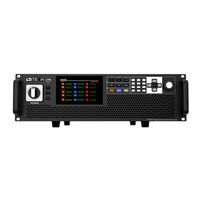
ITech IT79105P-350-630 User Manual (150 pages)
Programmable AC Power Supply
Brand:
ITech
| Category:
Power Supply
| Size: 4 MB
Table of Contents
Limitation of Warranty
3
Safety Symbols
3
Warranty
3
Environmental Conditions
5
Regulatory Markings
5
Waste Electrical and Electronic Equipment ( WEEE) Directive
6
Compliance Information
7
Table of Contents
8
Chapter1 Overview
11
Brief Introduction
11
Models and Options
11
Optional Accessories
12
Instrument Size Introduction
13
Chapter2 Instrument Introduction
19
Unpacking and Transportation
19
Verifying the Shipment
20
Front Panel
21
Keyboard
21
Push-On Knob
23
Rear Panel
23
Chapter3 Installation
26
Connectiong the Power Cord
26
Connecting Test Lines ( Optional)
29
Installing Fiber Cables (Only for IT7930P-350-180)
34
Chapter4 Getting Started
35
Power-On the Instrument
35
Home-Screen Overview
36
Touch Screen Introduction
39
Set Output Parameters
40
Output On/Off Control
40
Chapter5 Source Mode Operation
42
Full 4-Quadrant Output Character
42
Select the Power Supply Mode
42
Select the Output Mode
43
AC Output Mode
43
DC Output Mode
44
AC+DC Mode
45
DC+AC Mode
45
Current Limit Mode and Power Limit Mode
46
Protection Function
46
Current RMS Protection
47
Set the Current Peak Protection
48
Set Voltage/Current/Power Limit Range
48
Over-Temperature Protection (OTP)
49
Over-Power Protection (OPP)
49
Professional Anti-Islanding Test Mode
49
Waveform Selection
50
Full 4-Quadrant Power Amplifier
51
Auto-Range Function
51
Programmable Output Impedance
52
Sweep Function
52
List Function
54
Create a New List File
54
Select/Run List File
56
Import/Export List File
57
Setting of Surge/Sag Configuration
57
Self-Defined Waveform Function
59
Thd
59
Selfdefined
61
Voltage Sampling
62
Voltage Signals Simulation
64
Polyphase Function
66
Connecting the DUT
66
Connecting the System Bus Method
66
Connecting Digital I/O Method
68
Standard IEC Regulations
70
Chapter6 Operation And Application
73
Select Phase
73
Select the Input Mode
73
AC Input Mode
74
DC Input Mode
74
AC Load Function
74
Constant Current Mode (CC)
74
Constant Resistance Mode (CR)
76
Constant Power Mode (CP)
77
Constant Apparent Power Mode (CS)
78
Constant Current +Constant Resistance (CC+CR)
80
Circuit Emulation (CE)
81
DC Load Function
82
Constant Current Mode (CC)
83
Constant Resistance Mode (CR)
83
Constant Voltage Mode (CV)
83
Constant Power Mode (CP)
83
Complex Operation Mode
84
Rectified Mode
86
Waveform Selection
89
C Phase Loss
90
Three-Phase Unbalance Simulation
90
Load Angle and Unload Angle Control
90
Sweep Function
91
Synchronization Function
93
List Function
94
Create a New List File
94
Select/Run List File
97
Import/Export List File
97
Setting of Surge/Sag Configuration
98
Self-Defined Waveform Function
100
Thd
100
Selfdefined
101
Chapter7 System-Related Functions
103
System Menu Reference
103
Menu Function
109
Set the Communication Interface
111
View the System Information
111
Configuration Menu Reference
111
Key Lock Function
114
Switching Local/Remote Mode
114
Save and Recall Operations
115
Screen Capture Function
116
Trigger Function
116
Query the System Log
116
Query the Energy
116
Set Parallel Operation Mode
116
Remote Measurement Function
122
Digital I/O Function
122
Analogue Function (Ext-Program) (Optional)
125
Chapter8 Measurement Functions
129
Meter Mode
129
Oscilloscope Mode
130
Harmonic Measurement
132
Recorder Function
134
Chapter9 Technical Specifications
135
Main Technical Parameters
135
It7915P-350-90
135
Supplemental Characteristics
140
Chapter10 Remote Control
141
USB Interface
141
LAN Interface
141
CAN Interface
144
GPIB Interface (Optional)
145
Interface (Optional)
146
Commonly Used Commands Overview
147
Demo Software Introduction
148
Appendix
149
Specifications of Red and Black Test Lines
149
Advertisement
Related Products
ITech IT79105-350-630
ITech IT79105EP-350-525
ITech IT7915-350-90
ITech IT79150-350-900
ITech IT79165-350-990
ITech IT7912P-350-90
ITech IT7915P-350-90
ITech IT79120P-350-720
ITech IT79135P-350-810
ITech IT79165P-350-990
ITech Categories
Power Supply
Test Equipment
Measuring Instruments
Watch
Racks & Stands
More ITech Manuals
Login
Sign In
OR
Sign in with Facebook
Sign in with Google
Upload manual
Upload from disk
Upload from URL