
Related Manuals for ITech IT6300 Series


Summary of Contents for ITech IT6300 Series
- Page 1 Triple Output Programmable DC Power Supply IT6300 Series User Manual Model: IT6322A/IT6332A/IT6333A IT6322B/IT6332B/IT6333B IT6322C/IT6332C/IT6333C Version: V2.2...
- Page 2 Notices Warranty Safety Notices © Itech Electronic, Co., Ltd. 2019 The materials contained in this No part of this manual may be document are provided “as is”, and reproduced in any form or by any means (including electronic storage is subject to change, without prior retrieval or translation into a foreign notice, in future editions.
-
Page 3: Warranty
Warranty ITECH warrants that the product will be free from defects in material and workmanship under normal use for a period of one (1) year from the date of delivery (except those described in the Limitation of Warranty below). -
Page 4: Safety Precautions
Failure to comply with these precautions or specific warnings elsewhere in this manual will constitute a default under safety standards of design, manufacture and intended use of the instrument. ITECH assumes no liability for the customer’s failure to comply with these precautions. ... -
Page 5: Regulatory Markings
The expected useful life of the product is 10 years. The product can be used safely during the 10-year Environment Friendly Use Period (EFUP). Upon expiration of the EFUP, the product must be immediately recycled. Copyright © Itech Electronic Co., Ltd. -
Page 6: Waste Electrical And Electronic Equipment (Weee) Directive
With reference to the equipment classifications described in the Annex 1 of the WEEE Directive, this instrument is classified as a “Monitoring and Control Instrument”. To return this unwanted instrument, contact your nearest ITECH office. Copyright © Itech Electronic Co., Ltd. -
Page 7: Compliance Information
Connection of the instrument to a test object may produce radiations beyond the specified limit. Use high-performance shielded interface cable to ensure conformity with the EMC standards listed above. Safety Standard IEC 61010-1:2010/ EN 61010-1:2010 Copyright © Itech Electronic Co., Ltd. -
Page 8: Table Of Contents
3.11 Over Temperature Protection .......................... 16 3.12 Menu Description............................. 16 3.13 Rear Panel Terminals Function ......................... 26 Chapter4 Technical Specifications........................ 28 4.1 Major technical parameters ..........................28 4.2 Supplemental Characteristics ..........................42 Chapter5 Communication with PC ....................... 43 Copyright © Itech Electronic Co., Ltd. viii... - Page 9 IT6300 User Manual 5.1 RS232 interface ..............................43 5.2 USB interface ..............................45 5.3 GPIB interface..............................45 5.4 LAN interface ..............................45 Appendix ................................49 Specifications of Red and Black Test Lines ....................... 49 Copyright © Itech Electronic Co., Ltd.
- Page 10 IT6300 User Manual Copyright © Itech Electronic Co., Ltd.
-
Page 11: Chapter1 Acceptance And Installation
After confirming that package contents are consistent and correct, please appropriately keep package box and related contents. The package requirements should be met when the instrument is returned to factory for repair. The IT6300 series power supply has the following optional accessories sold separately: Equipment Name... -
Page 12: Installation Position
The instrument should be installed at well-ventilated and rational-sized space. Please select appropriate space for installation based on the power supply size. Unit: millimeter (mm) IT6322A/IT6322B/IT6322C Models Detailed Dimension Drawing IT6332A/IT6333A/IT6332B/IT6333B/IT6332C/IT6333C Models Detailed Dimension Drawing Copyright © Itech Electronic Co., Ltd. -
Page 13: Adjustment Of Power Handle
Acceptance and Installation 1.3 Adjustment of Power Handle To adjust the position, grasp the handle by the sides and pull outward. Then rotate the handle to the desired position. Bench operation Handle Copyright © Itech Electronic Co., Ltd. -
Page 14: Installation Of Support
1.4 Installation of Support The IT6300 Series power supplies can be installed on a standard 19-inch support. IT-E151/ IT-E151A is an accessory prepared for user. The user can select the corresponding manual according to the purchased support model to install. -
Page 15: Chapter2 Quick Start
2.1 Brief Introduction IT6300 series triple output programmable DC power supply, the output voltage or current of each channel can be set from 0 to max rated value. -
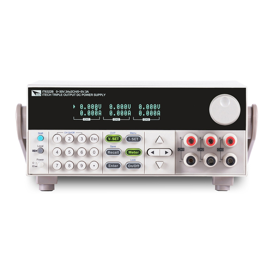
Page 16: Introduction To The Front Panel
IT6322B IT6332B IT6333B IT6322C IT6332C IT6333C 2.2 Introduction to the Front Panel The front panel of IT6300 series is shown in the next figure. VFD display Rotary knob Power switch, Local and Shift key Copyright © Itech Electronic Co., Ltd. -
Page 17: Introduction Of The Keypad
Function keys Up/Down/Left/Right keys Output terminals 2.3 Introduction of the Keypad The keypad of IT6300 series is shown in the next figure. Key Symbol Name & Function 0 to 9 Numeric keys. Use keys 1 to 3 to control the output state of the 3 channels which should coordinate with Shift key. -
Page 18: Introduction Of Indicators On The Screen
Indicates the channel currently selected. Enable tracking mode. 2.5 Introduction to the Rear Panel The rear panel of IT6322B/IT6332B/IT6333B is shown in the next figure. The rear panel of IT6322A/IT6332A/IT6333A is shown in the next figure. Copyright © Itech Electronic Co., Ltd. -
Page 19: Power-On Selftest
To avoid burning out, be sure to confirm that power voltage matches with supply voltage. Be sure to connect the main power socket to the power outlet of protective grounding. Do not use terminal board without protective Copyright © Itech Electronic Co., Ltd. - Page 20 Yes => 3 No => Please check the Power key to start power and check whether the exception is removed. Check whether the fuse of power supply is burned out. If yes, change fuse. Detailed steps: Copyright © Itech Electronic Co., Ltd.
-
Page 21: Output Verification
Adjust the voltage, then press to lit the key (indicates it is in the METER mode), make sure that the set value and output value are same, and if the current displayed on the VFD is nearly 0A. Copyright © Itech Electronic Co., Ltd. - Page 22 Make sure that the current can be adjusted from 0 to full rated value. Disable the output and then remove the short wire. Check the other two channels by the same method. Copyright © Itech Electronic Co., Ltd.
-
Page 23: Chapter3 Function And Features
Function and Features Chapter3 Function and Features This chapter will describe in detail how to use the buttons to complete the basic operation of the IT6300 series power supply. Will be divided into the following sections: Front panel operation introduction ... -
Page 24: Local/Remote Operation Switching
When the power supply is in remote mode, you can set the output state by sending SCPI command (OUTPut: ON | OFF). The output state operation does not affect any other parameter. Copyright © Itech Electronic Co., Ltd. -
Page 25: Timer Operation
Press confirm. I-set I-set Solution 3: press , then press to move the cursor Enter position and adjust the current value using . Press confirm. Copyright © Itech Electronic Co., Ltd. -
Page 26: Save And Recall Operation
Over Temperature… 3.12 Menu Description I-set I-set Press (Shift)+ (Menu) to enter the menu. View the menu on the VFD, and use the right/left key to change the setup, and up/down key to scroll Copyright © Itech Electronic Co., Ltd. - Page 27 IT6300B/ IT6300C Communi series only) cation Address GPIB communications address Address= 1~30 Choose USB communication interface And, the IT6300C series supports USBTMC and USBVCP options. LAN (For Choose LAN communication interface IT6300C series only) Copyright © Itech Electronic Co., Ltd.
- Page 28 MDNS: mDNS function switch, On/Off. Ping: Ping function switch, On/Off. Telnet-scpi: Telnet function switch, On/Off. Web: Web function switch, On/Off. VXI: VXI-11 function switch, On/Off. RawSocket: RAWSocket function switch, On/Off. Copyright © Itech Electronic Co., Ltd.
- Page 29 System Menu… First channel system menu Max volt Maximum Max voltage Set voltage setting Volt=31.000V Out timer Output Out Timer State timer status setting Turn off the Disable timer function. Enable Turn on the Copyright © Itech Electronic Co., Ltd.
- Page 30 Power channel combination status selection Cancel the current string/parallel status. Series Choose… Select serial connect mode Series Connect CH1 and CH2 in CH1+CH2 serial Parallel Choose… Select parallel connect mode Parallel Connect CH1 and CH2 in CH1+CH2 parallel Copyright © Itech Electronic Co., Ltd.
- Page 31 Optional settings of parity bit for serial communication are NONE, ODD and EVEN. Default setting is NONE. GPIB This item set the communication address for GPIB interface. Available range is 1-30. Copyright © Itech Electronic Co., Ltd.
- Page 32 The max voltage you set should be within the range of 0V to the maximum rated voltage. You can edit this value using the keys or via numerical Enter key pad followed by . The default setting is the maximum rated voltage for each channel. Copyright © Itech Electronic Co., Ltd.
- Page 33 When enable series connection mode, the front panel will indicate “Series success!” and escape this screen after 2S. Front display as follows in condition of output off and meter state. Wiring in serial mode: Copyright © Itech Electronic Co., Ltd.
- Page 34 Possible combination mode is CH1+CH2, CH2+CH3, ALL. Enter Press button to confirm your set. And press to quit the operation. Before setting the track mode, you need to set the voltage and current of Copyright © Itech Electronic Co., Ltd.
- Page 35 0V. The channels configured to serial, parallel or tracking mode will be add a label of “[ ]” in the display. Power Information Press (Shift) + , VFD will display power information, the information Copyright © Itech Electronic Co., Ltd.
-
Page 36: Rear Panel Terminals Function
Enable remote sense function: Remove the shorting clip between “S+” and “+”, “S-” and “-”. Connect “S+” and “S-” to the device under test. Connect “+” and “-” to the device under test. Copyright © Itech Electronic Co., Ltd. - Page 37 Function and Features NOTE To ensure the system stability, please use twisted-pair cables between sense terminal and load. Copyright © Itech Electronic Co., Ltd.
-
Page 38: Chapter4 Technical Specifications
Voltage coefficient ≤0.1%+5mA Current (%of output + offset) ≤0.02%+5mV Voltage Parallel setup accuracy ≤0.1%+20mA Current Memory Save/recall 36 groups Function Output timer Timer Time set 0.1~99999.9 second Resolution 0.1 second Working temperature 0-40° C Copyright © Itech Electronic Co., Ltd. - Page 39 (0 ° C ~ 40 ° C) ≤0.1%+5mA ≤0.1%+5mA ≤0.1%+5mA Current (%of output+offset)/ ≤0.03%+10mV Read-back Voltage Temp. coefficient ≤0.1%+5mA (0 ° C ~ 40 ° C) Current (%of output+offset) Voltage Series setup resolution Current Copyright © Itech Electronic Co., Ltd.
- Page 40 W×H×D 214.5mm×88.2mm×451.6mm the cabinet) Dimension W×H×D 255.3mm×108.7mm×471mm (Overall) Weight 15Kg IT6333A Parameters Voltage 0-60V 0-60V 0-5V Voltage Rated values limiting (0 ° C - 40 ° C) Current 0-3A 0-3A 0-3A Power 180W 180W Copyright © Itech Electronic Co., Ltd.
- Page 41 ≤0.1%+5mA Current (%of output+offset) ≤0.03%+10mV Read-back Temp. Voltage coefficient ≤0.1%+5mA Current (%of output+offset) 0-99V Voltage Series setup 100-120V 10mV resolution Current 0-99V Voltage Series Read-back 100-120V 10mV resolution Current Voltage Parallel setup resolution Current Copyright © Itech Electronic Co., Ltd.
- Page 42 (0 ° C - 40 ° C) Current 0~3A 0~3A 0~3A Power ≤0.01%+3mV Load regulation Voltage ≤0.1%+3mA (%of output + offset) Current ≤0.01%+3mV Voltage Line regulation ≤0.1%+3mA (%of output + offset) Current Setup resolution Voltage Copyright © Itech Electronic Co., Ltd.
- Page 43 180W 180W ≤0.01%+3mV ≤0.01%+3mV ≤0.01%+3mV Load regulation Voltage (%of output + ≤0.01%+3mA ≤0.01%+3mA ≤0.01%+3mA Current offset) ≤0.01%+3mV ≤0.01%+3mV ≤0.01%+3mV Voltage Line regulation (%of output + ≤0.01%+3mA ≤0.01%+3mA ≤0.01%+3mA Current offset) Voltage Setup resolution Current Copyright © Itech Electronic Co., Ltd.
- Page 44 0 - 9.999A - 1mA resolution Current 10 - 12A - 10mA ≤0.02%+5mV Voltage Parallel setup accuracy ≤0.1%+30mA Current Voltage waveform rise time Typical value < 100 ms < 100 ms < 100 ms 10%-90% change time Copyright © Itech Electronic Co., Ltd.
- Page 45 Setup resolution Current Read-back Voltage resolution Current Setup accuracy ≤0.03%+10mV ≤0.03%+10mV ≤0.03%+10mV Voltage (Within 12 months) (25° C ± 5 ° C) ≤0.1%+5mA ≤0.1%+5mA ≤0.1%+5mA Current (%of output + offset) ≤0.03%+10mV ≤0.03%+10mV ≤0.03%+10mV Read-back Voltage Copyright © Itech Electronic Co., Ltd.
- Page 46 < 100 ms 10%-90% change time Voltage waveform fall time Typical value < 1.5 s < 1.5 s < 100 ms 10%-90% change time Voltage dynamic Restore to 75 response time, < 50 us Load change Copyright © Itech Electronic Co., Ltd.
- Page 47 (%of output + offset) ≤1mVrms/3mVp-p Voltage Ripple and noise ≤3mArms Current Output Temp. ≤0.03%+10mV Voltage coefficient (0 ° C ~ 40 ° C) ≤0.1%+5mA Current (%of output+offset) ≤0.03%+10mV Voltage Read-back Temp. ≤0.1%+5mA coefficient Current Copyright © Itech Electronic Co., Ltd.
- Page 48 0-6A 0-6A 0-3A Power 180W 180W ≤0.01%+3mV ≤0.01%+3mV ≤0.01%+3mV Load regulation Voltage (%of output + ≤0.01%+3mA ≤0.01%+3mA ≤0.01%+3mA Current offset) ≤0.01%+3mV ≤0.01%+3mV ≤0.01%+3mV Line regulation Voltage (%of output + ≤0.01%+3mA ≤0.01%+3mA ≤0.01%+3mA Current offset) Copyright © Itech Electronic Co., Ltd.
- Page 49 0 - 9.999A - 1mA resolution Current 10 - 12A - 10mA ≤0.02%+5mV Voltage Parallel setup accuracy ≤0.1%+30mA Current Voltage waveform rise time Typical value < 100 ms < 100 ms < 100 ms 10%-90% change time Copyright © Itech Electronic Co., Ltd.
- Page 50 Setup resolution Current Read-back Voltage resolution Current Setup accuracy ≤0.03%+10mV ≤0.03%+10mV ≤0.03%+10mV Voltage (Within 12 months) (25° C ± 5 ° C) ≤0.1%+5mA ≤0.1%+5mA ≤0.1%+5mA Current (%of output + offset) ≤0.03%+10mV ≤0.03%+10mV ≤0.03%+10mV Read-back Voltage Copyright © Itech Electronic Co., Ltd.
- Page 51 10%-90% change time Voltage waveform fall time Typical value < 1.5 s < 1.5 s < 100 ms 10%-90% change time Voltage dynamic response time, Restore to 50 < 50 us Load change 50%-100% Copyright © Itech Electronic Co., Ltd.
-
Page 52: Supplemental Characteristics
*The above specifications may be subject to change without prior notice. 4.2 Supplemental Characteristics Recommended calibration frequency: once a year Maximum input power: Model IT6322A/IT6322B/IT6322C IT6332A/IT6332B/IT6332C IT6333A/IT6333B/IT6333C Power 750VA 1000VA 1000VA Cooling style: fans Copyright © Itech Electronic Co., Ltd. -
Page 53: Chapter5 Communication With Pc
If your computer connects with RS-232 interface with DB-25 plug, you need a cable and an adapter which one aspect of the matter is DB-25 plug the other end is DB-9 plug. Copyright © Itech Electronic Co., Ltd. - Page 54 Eight data bits have even check Eight data bits have odd check NONE Eight data bits have no check The machine address: (0 ~ 31, the factory a value of 0) Start Bit 8 Data Bits Parity=None Stop Bit Copyright © Itech Electronic Co., Ltd.
-
Page 55: Usb Interface
USBVCP is a virtual serial port (fixed to 9600/8/N/1). Before starting communication with the PC, you need to install VCP related drivers. Please contact ITECH Technical Support for the driver. The power supply USB488 interface functions are described as follows: ... - Page 56 LAN administrator for server details. The same numbering notation applies as for the IP Address. A value of 0.0.0.0 indicates that no default server is defined. Socket Port: This value indicates the port number corresponding to the Copyright © Itech Electronic Co., Ltd.
- Page 57 Press [Shift]+[I-set] ( Menu ) to enter into the menu setting interface. Use left/right key or rotate the knob to select Config > Communication and press [Enter] to confirm. Use left/right key or rotate the knob to select LAN and press [Enter] to Copyright © Itech Electronic Co., Ltd.
- Page 58 NO: indicates refuse to reset the LAN to the default settings. – YES: indicates reset the LAN to the default settings. After the setting is completed, press [Esc] to exit. Restart the instrument and the modified configuration item will take effect. Copyright © Itech Electronic Co., Ltd.
-
Page 59: Appendix
Specifications of Red and Black Test Lines ITECH provides you with optional red and black test lines, which individual sales and you can select for test. For specifications of ITECH test lines and maximum current values, refer to the table below. - Page 60 Contact Us Thanks for purchasing ITECH products. In case of any doubts, please contact us as follows: 1. Refer to accompanying data disk and relevant manual. 2. Visit ITECH website:www.itechate.com 3. Select the most convenient contact method, for further information.
Need help?
Do you have a question about the IT6300 Series and is the answer not in the manual?
Questions and answers