ITech IT6922A User Manual
Series it6900 programmable dc power
supply
Hide thumbs
Also See for IT6922A:
- User manual (50 pages) ,
- Programming manual (57 pages) ,
- User manual (47 pages)

Related Manuals for ITech IT6922A


Summary of Contents for ITech IT6922A
- Page 1 Programmable DC Power Supply Series IT6900 User Manual Model: IT6922A/IT6932A/IT6933A/IT6942A/ IT6952A/IT6953A/IT6922B/ IT6932B/IT6942B/IT6952B/IT6953B Version: V2.0...
- Page 2 (including electronic storage and “Caution” signs indicate danger. It is extent of laws, ITECH is not committed retrieval or translation into a foreign required to pay attention to the contents to any explicit or implied guarantee for...
-
Page 3: Warranty Service
ITECH, and ITECH will be responsible for return freight. If the product is sent to ITECH for warranty service from other countries, the customer will be responsible for all the freight, duties and other taxes. Limitation of Warranty This Warranty will be rendered invalid in case of the following: ... - Page 4 In case of failure to follow these precautions or specific warnings in other parts of the manual, violation against the safety standards related to the design, manufacture and purpose of the instrument will occur. If the user does not follow these precautions, ITECH will bear no responsibility arising there from. ...
-
Page 5: Regulation Tag
The instrument complies with the WEEE Directive (2002/96/EC) marking requirement. This affixed product label indicates that you must not discard the electrical/electronic product in domestic household waste. Copyright ©ITECH Electronics Co., Ltd. -
Page 6: Waste Electrical And Electronic Equipment (Weee) Directive
According to the equipment classification in Annex I of the WEEE directive, this instrument belongs to the “Monitoring” product. If you want to return the unnecessary instrument, please contact the nearest sales office of ITECH. Copyright ©ITECH Electronics Co., Ltd. -
Page 7: Compliance Information
Connection of the instrument to a test object may produce radiations beyond the specified limit. Use high-performance shielded interface cable to ensure conformity with the EMC standards listed above. Safety Standard IEC 61010-1:2010/ EN 61010-1:2010 Copyright ©ITECH Electronics Co., Ltd. -
Page 8: Table Of Contents
3.12.2 RS485 and Output Sync signal interface ....................24 3.13 Analog control interface ..........................25 Chapter4 Technical Specification ........................27 Chapter5 Remote Operation Mode ....................... 33 5.1 RS232 interface ............................. 33 5.2 USB interface ..............................34 5.3 GPIB interface ............................... 35 Copyright ©ITECH Electronics Co., Ltd. viii... - Page 9 IT6900 User Manual 5.4 RS485 interface ............................. 35 Appendix ................................37 Specifications of Red and Black Test Lines ......................37 Copyright ©ITECH Electronics Co., Ltd.
-
Page 10: Chapter1 Inspection And Installation
IT6900 series power supply is supplied with the following optional accessories (sold separately): Item Model Remarks IT-E151A (Rack IT-E151A To mount the instrument on a special rack, mount kit) user may select this optional. Copyright ©ITECH Electronics Co., Ltd. -
Page 11: Instrument Size Introduction
IT6900 series power supply different models are not the same size, the detail size of the power supply are shown as below. IT6922A/IT6932A/IT6933A/IT6942A/IT6922B/IT6932B/IT6942B Models Dimension: Width: 214.5mm Height: 88.2mm Depth: 345mm Detailed Dimension Drawing Copyright ©ITECH Electronics Co., Ltd. -
Page 12: Certification And Quality Assurance
Depth: 446mm Detailed Dimension Drawing 1.3 Rack Mounting IT6900 series power supply can be mounted on a standard 19” rack. ITECH provides user with IT-E151A rack, an optional mount kit. 1.4 Connecting the Power Cord Connect power cord of standard accessories and ensure that the power is under normal power supply. -
Page 13: Safety Precautions
If the power cord included in the instrument you purchased does not match the voltage, contact the dealer or manufacturer for change. China United States & Europe England Canada & Japan IT-E171 IT-E173 IT-E174 IT-E172 Copyright ©ITECH Electronics Co., Ltd. -
Page 14: Environmental Conditions
When you select 20V for the output voltage, the maximum output current 100W/20V = 5A, but when the output voltage is down to 10V, due to IT6922A maximum current is 5A, so in this case the maximum output current is 5A. -
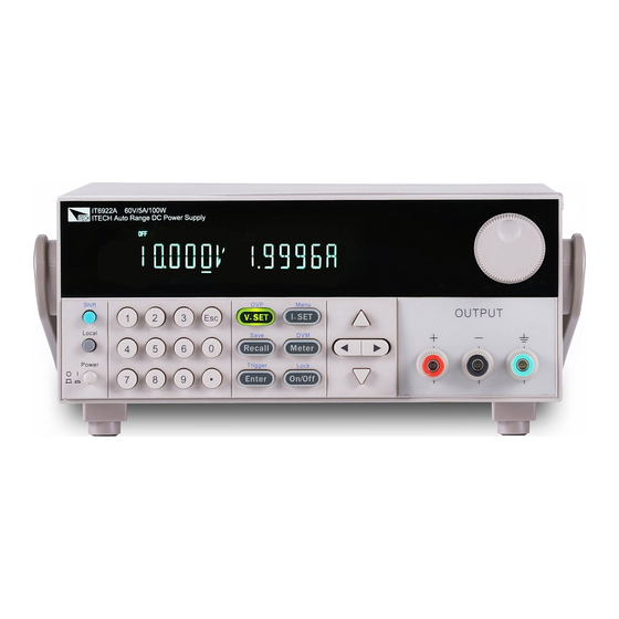
Page 15: Introduction To Front Panel
The front panel of IT6900 series is shown in the next figure. VFD display Rotary knob Compound key, the local switch key and power switch Number keys and ESC Function keys UP/DOWN/LEFT and RIGHT key, to move cursor Output terminals Copyright ©ITECH Electronics Co., Ltd. -
Page 16: Key Introduction
Left and right movement keys, used to set the value, to adjust the cursor to the specified location. Up and down keys, used to select a item in the menu or increase (decrease) the output voltage or current values. Cancel /return keys. Copyright ©ITECH Electronics Co., Ltd. -
Page 17: Vfd Description
Use compound keys Error fault OVP function state on Prot OVP OTP Protection Key operation is locked by Lock Password 2.5 Introduction to rear panel The rear panel of IT6922A/IT6932A/IT6933A/IT6942A is shown in the next figure. Copyright ©ITECH Electronics Co., Ltd. - Page 18 GPIB Communication cable interface DVM input terminal, Remote measurement terminal and the output terminal AC power socket Fuse The rear panel of IT6922B/IT6932B/IT6942B is shown in the next figure. Cooling window RS232 Communication cable interface Copyright ©ITECH Electronics Co., Ltd.
-
Page 19: Power-On Self-Test
Before operation, please confirm that you have fully understood the safety instructions. To avoid burning out, be sure to confirm that power voltage matches with supply voltage. Be sure to connect the main power socket to the power outlet of protective Copyright ©ITECH Electronics Co., Ltd. - Page 20 3. Check whether the fuse of power supply is burned out. If yes, change fuse. Detailed steps: 1) Pull out power line and take out the fuse box at power line jack with a small screw driver. As shown below. Copyright ©ITECH Electronics Co., Ltd.
- Page 21 T6.3A 250V IT6952B T15A 250V T10A 250V IT6953B T15A 250V T10A 250V 3) After replacement, install the fuse box back to original position, as shown below. NOTE Fuse of IT6952A/IT6953A/IT6952B/IT6953B can unscrew directly by hand. Copyright ©ITECH Electronics Co., Ltd.
-
Page 22: Chapter3 Function And Features
This indicates that you can set current. There are three ways to set output current through front panel. I-set I-set The first way: press ,adjust cursor location through button, push will enable you to adjust the setting current value. Copyright ©ITECH Electronics Co., Ltd. -
Page 23: On/Off Operation
25V/10A,in fact, the unit can only output 25V/8A. 3.7 Saving Operation Customer can save some often-used parameters in nonvolatile memory. Recall can use the button (Save) button or SCPI order *SAV、*RCL to achieve this function. Saving parameters include: setting voltage/setting current Copyright ©ITECH Electronics Co., Ltd. -
Page 24: Trigger Operation
Enter the screen will display the following functions .Press button will enter corresponding items. Press button will return to previous menu. IT6922A/IT6932A/IT6933A/IT6942A/IT6952A/IT6953A power supply menu function is shown as below. MAX VOLT Set the max output voltage SYST SET Reset... - Page 25 SN SN-2 the middle six number of SN SN-3 the last six number of SN EXIT Quit the information menu EXIT MENU Quit the main menu IT6922B/IT6932B/IT6942B/IT6952B/IT6953B power supply menu function is shown as below. Copyright ©ITECH Electronics Co., Ltd.
- Page 26 Unlock the rotary knob function Disable external signal control function Ext-C Enable external analog control function DIGIT Enable external digital control function MANU Local keyboard trigger TRIG (MANUAL) External trigger MEM (GROUP1) GRP1-8 Save and recall operation Copyright ©ITECH Electronics Co., Ltd.
- Page 27 The range of setting voltage is from 0V to rated voltage. You can press I-set I-set (Menu) button to enter the menu, then press direction key to Enter select >MAX VOLT item. Press button to confirm. After you set the Copyright ©ITECH Electronics Co., Ltd.
- Page 28 The default set is in OFF option. This function will be described in details below. Trigger mode (>TRIG) Before you running a list file, you need a trigger signal. Thus you must set the Copyright ©ITECH Electronics Co., Ltd.
- Page 29 Reset (>RESET) This item is used to reset all items in the menu. If you select >YES, then unit will restored to factory setting. If you select >NO, all setting in the menu will remain unchanged. Copyright ©ITECH Electronics Co., Ltd.
- Page 30 6. VFD display ISET 0.0000, press number key or rotary knob to Enter set the single-step current, press to confirm. 7. VFD display SET 0.1,press number key or rotary knob to set Enter single-step delay time,press to confirm. Copyright ©ITECH Electronics Co., Ltd.
- Page 31 (Trigger) to give a trigger signal, the list file can be ran. 18. In LIST mode, voltage set and current set button can’t be used, In LIST STATE item, choose LIST>OFF will enable you to quit list mode. Copyright ©ITECH Electronics Co., Ltd.
-
Page 32: Ovp Function
IT6900 series power supply has four semi-digital voltmeter. This DVM can Meter Meter (DVM)button can measure 0.001V to 61.000V voltage. Press enable the measured value display on the VFD screen. Press any key to quit Copyright ©ITECH Electronics Co., Ltd. -
Page 33: Rs485 And Output Sync Signal Interface
Please note that the positive and negative polarity when wiring, otherwise it will damage the instrument! 3.12.2 RS485 and Output Sync signal interface Terminals on IT6922B/IT6932B/IT6942B/IT6952B/IT6953B power supply rear board comprise Output Sync signal interface and RS485 communication interface, as shown below. Copyright ©ITECH Electronics Co., Ltd. -
Page 34: Analog Control Interface
Label Description REF_10V 10V DC reference output Vs/D0 Composite terminal: Voltage programming input/ Digital D0 input terminal Is/D1 Composite terminal: Current programming input/ Digital D1 input terminal Digital D2 input terminal ON/OFF Control output state Copyright ©ITECH Electronics Co., Ltd. - Page 35 Function and Features Voltage monitoring output Current monitoring output NULL None Ground pin Copyright ©ITECH Electronics Co., Ltd.
-
Page 36: Chapter4 Technical Specification
(20Hz ~20MHz) current Sample rate 10HZ Dimension (mm) 214.5mmW×88.2mmH×354.6mmD Weight (net) 7.7Kg Parameters IT6933A voltage 0-150V Rated values current 0-5A (0 ° C~40 ° C) Power 200W AC Input voltage 220VAC ± 10%/110VAC ± 10% Copyright ©ITECH Electronics Co., Ltd. - Page 37 50 PPM/℃+30mV Setup Temp.coefficient ( 0 ° C~40 ° C) current 50 PPM/℃+30mA voltage 50 PPM/℃+30mV Readback Temp.coefficient ( 0 ° C~40 ° C) 50 PPM/℃+30mA current Working temperature 0-40℃ Storage temperature -10-70℃ Series number Copyright ©ITECH Electronics Co., Ltd.
- Page 38 Ripple (20Hz ~20MHz) ≤15mArms ≤15mArms current Sample rate 10HZ Dimension (mm) 214.5mmW×88.2mmH×445mmD 15Kg Weight (net) Parameters IT6922B IT6932B voltage 0~60V 0~60V Rated values current 0~5A 0~10A (0 ° C~40 ° C) Power 100W 200W Copyright ©ITECH Electronics Co., Ltd.
- Page 39 (0 ° C~40 ° C) Power 360W 600W ≤0.01%+30mV ≤0.01%+30mV voltage Load regulation (%of output+offset) ≤0.05%+6mA ≤0.1%+10mA current ≤0.01%+30mV ≤0.01%+30mV voltage Line regulation ± (%of output+offset) ≤0.05%+6mA ≤0.1%+10mA current voltage Setup resolution current 0.1mA 0.1mA Copyright ©ITECH Electronics Co., Ltd.
- Page 40 1mV(<100V) 10mV(≥100V) Readback resolution current 0.1mA Setup accuracy ≤0.03%+20mV voltage (within twelve months)(25° C± 5° C) ≤0.1%+25mA current (%of output+offset) Read back resolution ≤0.03%+20mV voltage (W)(25° C± 5° C) ≤0.1%+25mA current (%of output+offset) ≤50mVp-p Ripple voltage Copyright ©ITECH Electronics Co., Ltd.
- Page 41 (20Hz ~20MHz) ≤15mArms current voltage ≤150mS(10%-90%) Rise time voltage ≤7S(90%-10%) Fall time Transient voltage 0.2mS Response Time Sample rate 10HZ/S Dimension(mm) 214.5mmW×88.2mmH×445mmD Weight (net) 15Kg *The above specifications may be subject to change without prior notice. Copyright ©ITECH Electronics Co., Ltd.
-
Page 42: Chapter5 Remote Operation Mode
If your computer is using a RS-232 interface with DB-25 connector, you need a adapter cable with a DB-25 connector at one end and the other side is a DB-9(not blank modem cable) Copyright ©ITECH Electronics Co., Ltd. -
Page 43: Usb Interface
Local Address: (0 ~ 31, the factory default setting is 0) Parity=None Start Bit 8 Data Bits Stop Bit 5.2 USB interface Use a Cable with two USB port to connect the power and the computer. Copyright ©ITECH Electronics Co., Ltd. -
Page 44: Gpib Interface
Stop Bit To set the multi-unit connection mode, access the menu system Menu→SYST SET→COMM→RS485→MODE→MUX, to turn on the chain mode. Set each unit with a different Address (0 ~ 30). Then by using RS485, connect Copyright ©ITECH Electronics Co., Ltd. - Page 45 PC. Now, multiple units daisy-chained via RS485 can be controlled by one PC by using the commands specific for multi-unit connection. See “Programming Guide” section for details. Connect PC Copyright ©ITECH Electronics Co., Ltd.
-
Page 46: Appendix
Specifications of Red and Black Test Lines ITECH provides you with optional red and black test lines, which individual sales and you can select for test. For specifications of ITECH test lines and maximum current values, refer to the table below. - Page 47 Contact Us Thanks for purchasing ITECH products. In case of any doubts, please contact us as follows: 1. Refer to accompanying data disk and relevant manual. 2. Visit ITECH website:www.itechate.com 3. Select the most convenient contact method, for further information.
Need help?
Do you have a question about the IT6922A and is the answer not in the manual?
Questions and answers