Advertisement

Quick Links

DT6220
DT6222
DT6230
Quick Manual
capaNCDT
6200

Advertisement

Table of Contents
loading
Need help?

Need help?

Do you have a question about the capaNCDT 6200 and is the answer not in the manual?

Questions and answers

Summary of Contents for MICRO-EPSILON capaNCDT 6200

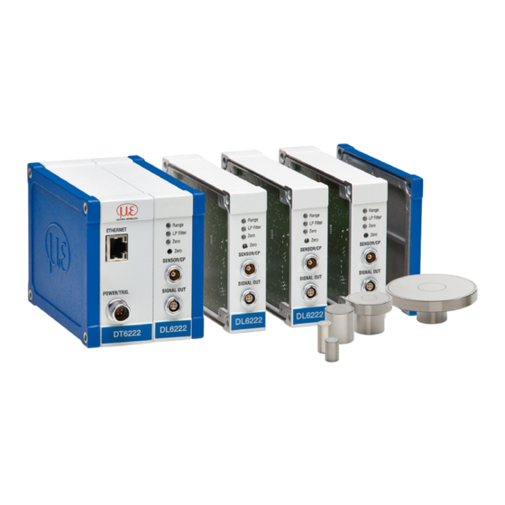
  • Page 1 Quick Manual capaNCDT 6200 DT6220 DT6222 DT6230...
  • Page 2: Table Of Contents

    You can find further information about the measurement system in the oper- MICRO-EPSILON MESSTECHNIK ating instructions. They are available at: GmbH & Co. KG www.micro-epsilon.com/download/manuals/man--capaNCDT-6200--en.pdf Koenigbacher Str. 15 www.micro-epsilon.com/download/manuals/man--capaNCDT-6222--en.pdf 94496 Ortenburg / Germany Tel. +49 (0) 8542 / 168-0 Fax +49 (0) 8542 / 168-90 e-mail info@micro-epsilon.com www.micro-epsilon.com...
  • Page 3: General

    General General Symbols Used The following symbols are used in this document: Indicates a hazardous situation which, if not avoided, may result in minor or moderate injury. Indicates a situation that may result in property damage if not avoided. Indicates a user action. Indicates a tip for users.
  • Page 4: Intended Use

    General Intended Use - The system is designed for use in an industrial environment. It is used for ƒ measuring displacement, distance, movement and thickness, ƒ measuring the position of parts or machine components. - The measuring system must only be operated within the limits specified in the technical data. - The measuring system must be used in such a way that no persons are endangered or machines and other materi- al goods are damaged in the event of malfunction or total failure of the measuring system.
  • Page 5: Proper Environment

    General Proper Environment Operation Storage Temperature range controller +10 ... +60 °C (+50 ... +140 °F) -10 ... +75 °C (+14 ... +167 °F) Temperature range sensor Operation Storage CS005, CS02, CS05, CS08, CS1, CS2, CS3, CS5, CS10 CSH02, CSH05, CSH1, CSH1.2, CSH2 -50 ...
  • Page 6: Setup, Connection Options

    General Setup, Connection Options Power supply and signal output are provided via plug con- nectors on the front of the controller. Controller EtherCAT (optional) LAN cable RJ-45 connectors CCxxx PS 2020 Ethernet Sensor Ammeter/Voltmeter capaNCDT 6220/6222/6230 Page 6...
  • Page 7: Ground Connection, Grounding

    DL62xx demodulators are synchronized. The schematic diagram below shows two synchronized capaNCDT sensors that measure against a roll. Since the sen- sors are connected by MICRO-EPSILON’s unique synchronization technology, grounding of the target is not required in most cases.
  • Page 8: Synchronization

    General Synchronization All sensors are synchronized with each other within one DT6220/6222/6230 controller. Several capaNCDT 6230 series controllers can be operated simultaneously as a multi-channel system. Synchronizing the controllers prevents interfer- ence of the sensors with each other. External synchronization DT6230 Assignment Insulation Color...
  • Page 9: Assembly

    Assembly Assembly Radial Spot Clamping with Grub Screw, Cylindrical Sensors No sharp or heavy objects should be allowed to affect the cable sheath. A damaged cable cannot be repaired. Tension on the cable is not permitted! Sensor Radial spot clamping with grub screw (1) - Simple mounting option Flush Protruding...
  • Page 10: Controller

    Assembly Controller DT 6220 DL 6220 Dimensional drawing of base module and demodulator Dimensional drawing of housing cover module capaNCDT 6220/6222/6230 Page 10...
  • Page 11: Inserting Demodulator Module

    Assembly Inserting Demodulator Module Loosen the sleeve nuts (4b) on the right side of the controller, remove the right housing cover (3). Pull out a sleeve nut (4a), including the threaded rod (1). Replace the threaded rod (1) with the next-longest threaded rod in the conversion kit supplied. Push the new threaded rod, including sleeve nut (4a), through the modules.
  • Page 12 Assembly Wiring to the previous demodulator module (5) can be Connect both flat strip connections (5) of the previ- released by using the supplied unplugging tool – see ous demodulator module to the new demodulator Accessories – as follows: module (6). Push the unplugging tool with the cutout side- ways onto the plug (5).
  • Page 13: Commissioning

    Commissioning Commissioning LEDs Range LP Filter Zero Zero SENSOR/CP SYNC POWER/TRIG. SIGNAL OUT 1) LP Filter can only be switched via Ethernet. Color Function Target within the measuring green range Range Measuring range exceeded Default strip width active 20 Hz low-pass filter at ana- Filter log outputs enabled.
  • Page 14 Commissioning Pin Assignment Supply, Trigger Wire color Description PC6200-3/4 Brown +24 VDC supply White GND supply SYNC Yellow Trigger IN+, TTL level POWER/TRIG. Green Trigger IN- DT62xx Shield PC6200-3/4 is an assembled supply and trigger View: solder side, Supply input on controller, 4-pin ODU female connector cable that is 3 m long.
  • Page 15 Commissioning Ethernet/EtherCAT Switching DT6230 Switch for changing between Ethernet and EtherCAT You can change between Ethernet and EtherCAT by using the hardware switch on the DT6230 base module or in the software. If the switch is in the EN ( ) position, the Ethernet Ethernet interface is always active irrespective of the software...
  • Page 16: Commissioning, Ip Address

    You can query the IP addresses of the address. controllers that are connected to a PC or network by using the sensorTOOL program. This program is available online at https:// www.micro-epsilon.com/download/software/ 2279 sensorTOOL.exe. Start the sensorTOOL program and click the button.
  • Page 17: Channel Information, Measuring Range

    Commissioning, IP Address Channel Information, Measuring Range Math Function The measuring ranges of the connected sensors must This function permits scaling of a measuring channel be specified manually. After replacing a sensor, don’t and mathematical linking of individual measuring chan- forget to specify its new measuring range.
  • Page 18: Positioning The Target

    Distance Measurements Positioning the Target Distance Measurements Position the target within the sensor mea- Switch to the Measurement menu. suring range. Click the Start measuring button. 10 V 20 mA 2279 12 mA Displacement 4 mA Target Sensor Measuring range (MR) Start of measuring range Mid of measuring range End of measuring range...
  • Page 19: Operation And Maintenance

    Ensure that the sensor surface is always clean. any defects occur despite careful quality control, these Before cleaning, turn off the supply voltage. shall be reported immediately to MICRO-EPSILON or to your distributor / retailer. Clean with a damp cloth and then rub the sensor MICRO-EPSILON undertakes no liability whatsoever for surface dry.
  • Page 20 MICRO-EPSILON MESSTECHNIK GmbH & Co. KG Koenigbacher Str. 15 · 94496 Ortenburg / Germany Tel. +49 (0) 8542 / 168-0 · Fax +49 (0) 8542 / 168-90 X9691298-A042112HDR info@micro-epsilon.com · www.micro-epsilon.com Your local contact: www.micro-epsilon.com/contact/worldwide/ MICRO-EPSILON MESSTECHNIK...

This manual is also suitable for:

Dt6220Dt6222Dt6230

Table of Contents