
Related Manuals for MICRO-EPSILON optoNCDT 1420


Summary of Contents for MICRO-EPSILON optoNCDT 1420
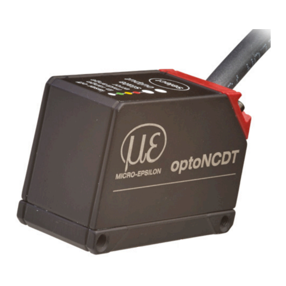
- Page 1 Operating Instructions optoNCDT 1420 ILD 1420-10 ILD 1420-500 ILD 1420-10LL ILD 1420-10CL1 ILD 1420-25 ILD 1420-25LL ILD 1420-25CL1 ILD 1420-50 ILD 1420-50LL ILD 1420-50CL1 ILD 1420-100 ILD 1420-200...
- Page 2 Intelligent laser optical displacement measurement MICRO-EPSILON MESSTECHNIK GmbH & Co. KG Koenigbacher Str. 15 94496 Ortenburg / Germany Tel. +49 (0) 8542/168-0 Fax +49 (0) 8542/168-90 e-mail info@micro-epsilon.com www.micro-epsilon.com...
-
Page 3: Table Of Contents
Light from other Sources ................... 25 5.1.2.2 Color Differences ......................26 5.1.2.3 Temperature Influences ....................26 5.1.2.4 Mechanical Vibration ....................26 5.1.2.5 Movement Blurs ......................26 5.1.2.6 Surface Roughness ....................27 5.1.2.7 Angle Influences ......................28 5.1.3 Optimizing the Measuring Accuracy ................... 29 optoNCDT 1420... - Page 4 Triggering ............................56 7.4.4.1 General ........................56 7.4.4.2 Signal Processing - Trigger for Acquiring Values ............58 7.4.4.3 Signal Processing - Value Output Trigger ..............58 7.4.5 Mask Evaluation Area, ROI ......................59 7.4.6 Peak Selection ..........................60 optoNCDT 1420...
- Page 5 Digital Interfaces RS422 ......................85 Preliminary Remarks ............................85 Measurement Data Format ..........................85 Conversion of the Binary Data Format ......................86 Values, Ranges .............................. 87 Characteristics Digital Output ........................89 Cleaning ..........................91 Software Support with MEDAQLib ..................92 optoNCDT 1420...
- Page 6 A 3.3.10.2 UNIT, Web Interface ....................110 A 3.3.10.3 MFIFUNC, Function Selection Multifunctional Input ..........110 A 3.3.10.4 ERROROUT1, Activate Digital Output ............... 110 A 3.3.10.5 ERRORLEVELOUT1, Output Level Digital Output ............ 111 A 3.3.10.6 ERRORLIMIT ......................111 optoNCDT 1420...
- Page 7 Control Menu ............................... 120 A 4.1 Tab Home ..............................120 A 4.2 Tab Settings ..............................121 A 4.2.1 Inputs ............................121 A 4.2.2 Signal Processing ........................121 A 4.2.3 Outputs ............................123 A 4.2.4 System Settings .......................... 125 optoNCDT 1420...
-
Page 9: Safety
Caution - use of controls or adjustments or performance of procedures other than those specified may cause harm. Connect the power supply and the display/output device according to the safety regulations for electrical equip- ment. > Risk of injury > Damage to or destruction of the sensor optoNCDT 1420 Page 9... -
Page 10: Notes On Ce Marking
Avoid exposure of sensor to aggressive media (detergents, cooling emulsions). > Damage to or destruction of the sensor Notes on CE Marking The following apply to the optoNCDT 1420: - EU directive 2014/30/EU - EU directive 2011/65/EU Products which carry the CE mark satisfy the requirements of the EU directives cited and the relevant applicable harmonized European standards (EN). -
Page 11: Notes On Ukca Marking
The UKCA Declaration of Conformity and the technical documentation are available to the responsible authorities according to the UKCA Directives. Intended Use - The optoNCDT 1420 system is designed for use in industrial and laboratory applications. - It is used for ƒ measuring displacement, distance, position and thickness ƒ... -
Page 12: Laser Safety
ILD1420 / ILD1420LL The optoNCDT 1420 / 1420LL operates with a semiconductor laser with a wavelength of 670 nm (visible/red). The sensors fall within laser class 2. The laser is operated on a pulsed mode, the maximum optical power is ≤ 1 mW. The pulse frequency depends on the adjusted measuring rate (0.25 ... - Page 13 The housing of the optical sensors may only be opened by the manufacturer, see 11. For repair and service purposes, the sensors must always be sent to the manufacturer. Please observe national regulations, e. g., Laser Notice No. 50 for the USA. optoNCDT 1420 Page 13...
-
Page 14: Ild1420 Cl1
Laser Safety ILD1420 CL1 The optoNCDT 1420 CL1 operates with a semiconductor laser with a wavelength of 670 nm (visible/red). The maximum optical power is ≤ 0.39 mW. The sensors fall within laser class 1. The accessible radiation is harmless under predictable conditions. For class 1 laser devices, impairment of color vision and distur- bances, e.g., from a glare effect, cannot be excluded. - Page 15 Laser operation is indicated by LED, see 5.3. The housing of the optical sensors may only be opened by the manufacturer, see For repair and service purposes, the sensors must always be sent to the manufacturer. optoNCDT 1420 Page 15...
-
Page 16: Functional Principle, Technical Data
Functional Principle, Technical Data Short Description The optoNCDT 1420 uses the principle of optical triangulation, that is, a visible, modulated point of light is projected onto the target surface. The diffuse part of the reflection of this point of light is displayed depending on distance on a position-resolving element (CMOS) by an receiver optic which is arranged to the optical axis of the laser beam in a defined angle. -
Page 17: Auto Target Compensation (Atc)
Functional Principle, Technical Data Auto Target Compensation (ATC) The Auto Target Compensation (ATC) enables stable compensation independent of color and brightness of the measuring object. Also small objects can be detected reliably thanks to the small measuring spot. optoNCDT 1420 Page 17... -
Page 18: Technical Data Ild1420
1 x HTL multifunction input: trigger in, zero setting, mastering, teach Digital interface RS422 (16 bit) / EtherCAT PROFINET / EtherNet/IP 4 … 20 mA / 1 … 5 V with cable PCF1420-3/U Analog output (16 bit; freely scalable within the measuring range) optoNCDT 1420 Page 18... - Page 19 SMR = Start of measuring range; MMR = Mid of measuring range; EMR = End of measuring range The specified data apply to a white, diffuse reflecting surface (Micro-Epsilon reference ceramic for ILD sensors) 1) Factory setting 4 kHz, modifying the factory setting requires the IF2001/USB converter (see accessories) 2) Messrate 2 kHz, Median 9 3) The specified value is only achieved by mounting on a metallic sensor holder.
-
Page 20: Technical Data Ild1420Ll
1 x HTL multifunction input: trigger in, zero setting, mastering, teach Digital interface RS422 (16 bit) / EtherCAT PROFINET / EtherNet/IP 4 … 20 mA / 1 … 5 V with cable PCF1420-3/U Analog output (16 bit; freely scalable within the measuring range) optoNCDT 1420 Page 20... - Page 21 4) Light spot diameter with line-shaped laser determined based on the emulated 90/10 knife-edge method 5) Illuminant: light bulb 6) Optional connection via interface module (see accessories) 7) Connection to PC via IF2001/USB (see accessories) optoNCDT 1420 Page 21...
-
Page 22: Technical Data Ild1420-Cl1
1 x HTL multifunction input: trigger in, zero setting, mastering, teach Digital interface RS422 (16 bit) / EtherCAT PROFINET EtherNet/IP 4 … 20 mA; 1 … 5 V with cable PCF1420-3/U Analog output (12 bit; freely scalable within the measuring range) optoNCDT 1420 Page 22... - Page 23 SMR = Start of measuring range; MMR = Mid of measuring range; EMR = End of measuring range The specified data apply to a white, diffuse reflecting surface (Micro-Epsilon reference ceramic for ILD sensors) 1) Factory setting 2 kHz, modifying the factory setting requires the IF2001/USB converter (see accessories) 2) Measuring rate 2 kHz, median 9 3) The specified value is only achieved by mounting on a metallic sensor holder.
-
Page 24: Delivery
- 10xxxxxx = ILD1420-10, ILD1420-25, ILD1420-50 - 30xxxxxx = ILD1420-10LL, ILD1420-25LL, ILD1420-50LL - 40xxxxxx = ILD1420-100, ILD1420-200, ILD1420-500 Serial numbers for sensors with the old design can be recognized by the following structure: JJMMxxxx (J = year, M = month) optoNCDT 1420 Page 24... -
Page 25: Installation
Light from other Sources Thanks to their integrated optical interference filters the optoNCDT 1420 sensors offer outstanding performance in suppressing light from other sources. However, this does not preclude the possibility of interference from other light sources if the objects being mea- sured are shiny and if lower measuring rates are selected. -
Page 26: Color Differences
If the objects being measured are fast moving and the measuring rate is low, it is possible that movement blurs may result. Always select a high measuring rate for high-speed operations, therefore, in order to prevent errors. optoNCDT 1420 Page 26... -
Page 27: Surface Roughness
Ceramic reference surface Structured surface Recommendation for parameter choice: The averaging number should be selected in such a way that a surface area the size of which is comparable to those with mechanical measurements is averaged. optoNCDT 1420 Page 27... -
Page 28: Angle Influences
These influences have to be explicitly considered when scanning profiled surfaces. Basically the angle behavior of triangulation is li- able to the reflectivity of the measuring object surface. X-axis Y-axis Angle Fig. 9 Measurement errors through tilting with diffuse reflection optoNCDT 1420 Page 28... -
Page 29: Optimizing The Measuring Accuracy
In case of bore holes, blind holes and edges in the surface of moving targets the sensor must be arranged in such a way that the edges do not obscure the laser spot. incorrect correct (shadow) Fig. 11 Sensor arrangement for holes and ridges optoNCDT 1420 Page 29... -
Page 30: Mounting, Dimensions
Mounting, Dimensions The optoNCDT 1420 sensor is an optical system for measurements with micrometer accuracy. The laser beam must be directed perpendicularly onto the surface of the target. In case of misalignment it is possible that the measurement results will not always be accurate. - Page 31 FSO = Full scale output (.08) (.31) Fig. 13 Dimensional drawing and free space for optics A: 2x M3 for direct fastening or 2x M2 als through-bore (mounting hole) for bolt connection 47.5 Fig. 14 Dimensional drawing M12 cable connector optoNCDT 1420 Page 31...
-
Page 32: Indicator Elements At Sensor
The programmable select key calls up the Masters and Teaching functions. By factory default the select key is only active for 5 minutes after switching on the supply voltage. After that it will be automatically locked. The keylock can be programmed via internal websites or ASCII commands. optoNCDT 1420 Page 32... -
Page 33: Electrical Connections
PCF1420-x/I and IF2035-PROFINET IF2035-EIP PCF1420-x/U IF2035-EtherCAT IF2001/USB IF2004/USB PS 2020 PCF1420-x/IF2008 (IF2008-Y) PCE1420-3/M12 PCF1420-x/IF2008 and IF2008-Y Ethernet adapter cable IF2008/ETH IF2008/PCIE PCF1420-x/C-Box Sensor supply is done by peripheral Ethernet C-Box/2A Fig. 15 Connection examples on ILD 1420 optoNCDT 1420 Page 33... - Page 34 IF2008/PCIE, PCI interface card four IF2008/ETH eight PLC, ILD 1420 or the like Functional input: trigger Switch, key, PLC or the like Switching input laser On/Off Fig. 16 Max. sensor channels on the peripheral devices optoNCDT 1420 Page 34...
-
Page 35: Pin Assignment
The PCF1420 supply and output cable is drag-chain suitable, see A 1 (optional accessory). One end of the cable has a molded M12 cable connector, the other end has braids with ferrules. 1) Integrated sensor cable, PCF1420-x/I and PCF1420-x/U optoNCDT 1420 Page 35... -
Page 36: Supply Voltage
Color or similar sources of pulse interference at 11 ... the same time. 30 VDC ILD1420 MICRO-EPSILON recommends using an optional available power supply unit PS2020 for the sensor. Power supply Blue ground Fig. 17 Connection of supply voltage 5.4.4... -
Page 37: Analog Output
1 ... 5 V at V > 11 V R = 500 Ohm: GND (Pin 12) Blue 2 ... 10 V at V > 17 V Fig. 19 Wiring for voltage output 1) The components are already included in PCF 1420-x/U. optoNCDT 1420 Page 37... -
Page 38: Multifunctional Input
Rx + (Pin 3) Green Tx + (Pin 1) Rx - (Pin 4) Yellow Tx - (Pin 2) GND (Pin 12) Blue GND (Pin 9) Fig. 21 Pin assignment IF2001/USB Cross the lines for connections between sensor and PC. optoNCDT 1420 Page 38... -
Page 39: Digital Output
PNP (High side) appr. GND Push-Pull Push-Pull, negated Fig. 23 Switching characteristic digital output Digital output is activated when measuring object is missing, measuring object too close/too far or when no valid measurement value can be determined. optoNCDT 1420 Page 39... -
Page 40: Connector And Sensor Cable
The fixed connected sensor cables are not cable carriers suitable. Unused open cable ends must be insulated to protect against short circuits or malfunction of the sensor. MICRO-EPSILON recommends the use of the drag-chain suitable PCF1420, see A 1 (optional accessories). -
Page 41: Operation
Operation Operation Getting Ready for Operation Install and assemble the optoNCDT 1420 in accordance with the instructions set out, see Connect the sensor with the indicator or monitoring unit and the power supply. The laser diode in the sensor can only be activated if at the input Laser on/off Pin 8 is connected with Pin 12, see 5.4.4. -
Page 42: Operation Via Web Interface
You need a web browser compatible with HTML5 on a PC/notebook. Choose the desired sensor. Click on the button Open Website. The program searches for connected ILD1420 sensors on available interfaces. Fig. 24 Auxiliary program for sensor search and to start web interface optoNCDT 1420 Page 42... -
Page 43: Access Via Web Interface
Fig. 25 First page after web interface has been accessed The appearance of the websites can change dependent of the functions. Dynamic help text with excerpts from the operating instruc- tions supports you during the sensor configuration. optoNCDT 1420 Page 43... -
Page 44: Calibration Protocol
The area Diagram type enables the change between graphical display of the measurement value or the video signal. 6.2.3 Calibration Protocol You can download the calibration pro- tocol under Download / Informa- tion in the Info menu item. optoNCDT 1420 Page 44... -
Page 45: Presets, Setups, Measurement Configuration, Signal Quality
Home > Measurement configuration You can select a setup in the tab Home > Measurement configuration or Settings in menu System settings > Load & save A setup can be stored permanently in the controller, see 7.4.6. optoNCDT 1420 Page 45... - Page 46 After programming all the settings are to be stored permanently in a set of parameters. The next time you turn on the sensor they are available again. Therefore use the button Save settings. 1) Available for the sensor models ILD1420-10/25/50. optoNCDT 1420 Page 46...
-
Page 47: Measurement Presentation Via Web Browser
Windows selection dialog for the file name and storage location to save the last 10.000 values in a CSV file (separation using semicolon), which were measured the last 10 seconds independently from the measuring rate. This function starts or stops a relative measurement. The master value can also e defined in a submenu here. optoNCDT 1420 Page 47... - Page 48 If you leave the diagram display in a separate tab or window of the browser running, you do not have to restart the description each time. Click the button Start, for starting the display of the measurement results. optoNCDT 1420 Page 48...
-
Page 49: Video Signal Via Web Browser
Stop stops the diagram; data selection and zoom function are still possible. Pause interrupts recording. Save opens the Windows selection dialog for the file name and storage location to save the video signal in a CSV file. optoNCDT 1420 Page 49... - Page 50 11 Scaling of the x-axis: you can enlarge (zoom) the overall signal by means of the left slider during ongoing measurement. If the diagram is stopped, you can also use the right slider. The zoom window can also be moved by means of the mouse in the middle of the zoom window (arrow cross). optoNCDT 1420 Page 50...
-
Page 51: Programming Via Ascii Commands
Each cycle takes 250 µs at a measuring rate of 4 kHz. The measured value N is available at the output after three cycles. The delay between acquisition and output is therefore 750 µs. As the processing in the cycles occurs parallel, after another 250 µs, the next measured value (N+1) is output. optoNCDT 1420 Page 51... -
Page 52: Set Sensor Parameter
If you do not save the programming permanently in the sensor, you lost the settings after turning off the sensor. Overview Parameter The following parameters can be set or changed in the optoNCDT 1420, see tab Settings. Inputs Laser on/off, Multifunctional input, Key function... -
Page 53: Inputs
You can find references to the chosen setting below. The menus for the area Signal processing are located in the left part. Value Grey shaded fields require a selection. Dark-bordered fields require you to specify a value. optoNCDT 1420 Page 53... -
Page 54: Measurement Task
In the setting Changing surfaces a compromise between penetration and standard finish is chosen which achieves optimum results for both materials. This can also be seen in the diagram distance values (Meas) by means of the different distance values for the respective measurement tasks. 1) Available for the sensor models ILD1420-10/25/50. optoNCDT 1420 Page 54... -
Page 55: Measuring Rate
With a maximum measuring rate of 8 kHz the CMOS element is exposed 8,000 times per second. The lower the measuring rate, the higher maximum exposure time. Measuring rate is set to 4 kHz ex works. Value Grey shaded fields require a selection. Dark-bordered fields require you to specify a value. optoNCDT 1420 Page 55... -
Page 56: Triggering
Triggering 7.4.4.1 General The optoNCDT 1420 measurement input and output is controllable through an external trigger signal or a command. Triggering affects the analog and digital output. The measurement value at the time of triggering is output delayed, see 6.5. - Page 57 If “0“ is selected for the number of measure- ment values, the sensor stops the triggering and the continuous value output. Measurement output can also be stopped by means of a command. optoNCDT 1420 Page 57...
-
Page 58: Signal Processing - Trigger For Acquiring Values
Measurement values are calculated continuously and independently of the trigger event. A trigger event simply triggers the value output via a digital interface. Therefore, any values measured immediately before the trigger event are included in calculating mean values (averages). Activating data output trigger deactivates data recording trigger. optoNCDT 1420 Page 58... -
Page 59: Mask Evaluation Area, Roi
Fig. 31 Light blue areas limit the evaluation area The exposure control optimizes the peaks in the evaluation range. Thus, small peaks can be optimally controlled when a high interfer- ing peak is outside the evaluation range. optoNCDT 1420 Page 59... -
Page 60: Peak Selection
After expiry of the chosen number an error value is output. Value Grey shaded fields require a selection. Dark-bordered fields require you to specify a value. optoNCDT 1420 Page 60... -
Page 61: Averaging
Averaging does not affect the measuring rate or data rates in digital measurement value output. The averaging numbers can also be used if programmed via the digital interfaces. The sensor optoNCDT 1420 is supplied ex factory with the default setting „Median 9“, that is, averaging with Median and 9 measurements. -
Page 62: Moving Average
Output value Characteristics: When moving averaging in the optoNCDT 1420 only powers of 2 for the averaging number N are allowed. Range of values for number of average N is 1 / 2 / 4 / 8 ... 128. optoNCDT 1420... -
Page 63: Recursive Average
Example: Average from five measurement values ... 0 1 2 4 5 1 3 Sorted measurement values: 1 2 3 4 5 Median ... 1 2 4 5 1 3 5 Sorted measurement values: 1 3 4 5 5 Median (n+1) optoNCDT 1420 Page 63... -
Page 64: Zeroing And Mastering
An invalid master value, e. g. no peak available, will be acknowledged with the E602 Master value is out of range error. Value Grey shaded fields require a selection. Dark-bordered fields require you to specify a value. optoNCDT 1420 Page 64... -
Page 65: Zeroing, Mastering With Select Key
Fig. 33 Flow chart for the return of zero setting and mastering 1) The key Select remains without effect since key lock is active. 2) The master value is not applied when LED State is red, flash frequency 8 Hz for 2 s. optoNCDT 1420 Page 65... -
Page 66: Zeroing, Mastering With Hardware Input
The function zeroing/mastering can be applied successive in several times. Between repeating the zeroing/mastering function a pause of 1 s is required. The zeroing/mastering function can also be combined with the select key. 1) With red State LED, the master value is not accepted, flashes with 8 Hz for 2 s. optoNCDT 1420 Page 66... -
Page 67: Data Reduction, Output Data Rate
PLC, to the fast sensor without having to reduce the measuring rate. Value Grey shaded fields require a selection. Dark-bordered fields require you to specify a value. optoNCDT 1420 Page 67... -
Page 68: Outputs
Output Interface Web interface / Analog / RS422 Decides via the used interface for measurement output. A parallel measurement output via multiple channels is not possible. When choosing web inter- face measurement values are not output via RS422 or current output. optoNCDT 1420 Page 68... -
Page 69: Digital Output, Rs422
Set Sensor Parameter 7.5.2 Digital Output, RS422 Details can be found in the description of the RS422 digital interface, see 8. optoNCDT 1420 Page 69... -
Page 70: Analog Output Scaling
- to close to the sensor - beyond SMR or - to far from the sensor - beyond EMR. LED State Error Error Measuring object Fig. 36 Default characteristic (black), reverse, within range Switching user defined characteristic (red) output optoNCDT 1420 Page 70... -
Page 71: Output Scaling With Key Select
If the key Select is pressed longer than 10 s or not within the timeframe while doing the return of the output scaling, an error is shown via State LED. In this case the State LED is blinking red with 8 Hz for 2 s. optoNCDT 1420 Page 71... -
Page 72: Output Scaling Via Hardware Input
200 ms t 5 - t 3 = 2 s Error 5 min 5 ... <10 s t 3 t 4 Fig. 40 Flow chart for the return of output scaling optoNCDT 1420 Page 72... -
Page 73: Calculation Of Measuring Value Using Analog Current
[>20; 20,2] EMR reserve [mm] * MR [mm] MR = measuring range [mm] {10/25/50/100/200/500} MP = master position [mm] [0; MR] for MP £ 0.5MR: [-MP; 0.5MR] = distance [mm] for MP > 0.5MR: [-0.5MR; MR - MP] optoNCDT 1420 Page 73... - Page 74 MR = measuring range [mm] {10/25/50} = position object [mm] [0; MR] for MP £ 0.5MR: [-MP; 0.5MR] m, n = teaching area [mm] for MP > 0.5MR: [-0,5MR; MR - MP] = distance [mm] [m; n] optoNCDT 1420 Page 74...
-
Page 75: Characteristics Distance Value And Analog Output
3.00 mA 4.00 mA 18.40 mA Analog maximum reached at 66 % MR Analog minimum reached at 10 % MR MR = measuring range, SMR = start of measuring range, EMR = end of measuring range optoNCDT 1420 Page 75... - Page 76 10 mm (30 mm) (-15 mm) (30 mm) 12 mA Out min 4 mA 3.8 mA 16 % 50 % 60 % 100 % Reserve measuring range Fig. 41 Analog output with zero setting or mastering optoNCDT 1420 Page 76...
-
Page 77: Mastering And Teaching Analog Output
30 mm 50 mm -10 mm 0 mm 10 mm SMR’ 60 % EMR’ 100 % MR Fig. 42 Analog output characteristic after mastering and scaling with an -10.0 mm 10.00 mm ILD1420-50 4.00 mA 20.00 mA optoNCDT 1420 Page 77... -
Page 78: System Settings
The web interface promotes the units millimeter (mm) and inch when displaying measuring results. You can choose German or English in the web interface. You can change language in the menu bar. Fig. 43 Language selection in the menu bar optoNCDT 1420 Page 78... -
Page 79: Keylock
The key Select is deactivated indepen- Active dent of the user level. The key Select is active independent of Inactive the user level. Value Grey shaded fields require a selection. Dark-bordered fields require you to specify a value. optoNCDT 1420 Page 79... -
Page 80: Load, Save
, e.g. area A. area A. rubber 1.21 and click the The dialog Setup management The dialog Setup management button Save. opens. opens. Click on the button Load. Click on the button Favorite. optoNCDT 1420 Page 80... - Page 81 The dialog Setup management opens. Click on the button Search. Click on the button Export. A Windows dialog for file selections opens. Choose the desired file and click on the button Open. Click the button Import in the setup management. optoNCDT 1420 Page 81...
-
Page 82: Import, Export
The operating system stores the set of parameters in the area Download. File name for the following example is <...\Downloads\ ILD1420_50BASICSETTINGS_Rubber 1.04..JSON> A security query, see adjacent figure, helps to avoid that an existing setup is inadvertently overwritten during import. optoNCDT 1420 Page 82... -
Page 83: Access Authorization
Type in the default password 000 or a user-defined password in the Password field and confirm with Login. Change with a click on the Logout button in the mode user. Fig. 46 Change in the professional user level optoNCDT 1420 Page 83... -
Page 84: Sensor Reset
Specifies the user level, with which the sensor starts after the re- restarting Professional starting. For this purpose, MICRO-EPSILON recommends the selection user. After configuration of the sensor the password protection is to be activated. Please note the password for later reference. -
Page 85: Digital Interfaces Rs422
An output value is divided into three bytes that differ in the two most significant bits. The transmission of additional output values is optional. Output value 1: Preamble Data bits L-Byte M-Byte H-Byte Output value 2 ... 32: Preamble Data bits L-Byte M-Byte H-Byte Output sequence: L-Byte, M-Byte, H-Byte. optoNCDT 1420 Page 85... -
Page 86: Conversion Of The Binary Data Format
Conversion must be done in the application program. D16 and D17 are among others used for interpretation of error codes or e.g. for the measurement counter. The sensor continues to deliver measurement values to the RS422 output even while communicating with the sensor. optoNCDT 1420 Page 86... -
Page 87: Values, Ranges
MV ≥ MP - 0.5MR: [-MP + MV; MR - MP+ MV] Exposure time 18 bits x = digital value [1; 262143] [µs] ET = exposure time [µs] [0.1; 26214.3] Intensity 16 bits x = digital value [0; 65472] 16368 = intensity [%] [0; 100] optoNCDT 1420 Page 87... - Page 88 262076 no peak available 262077 peak before the measurement range (MR) 262078 peak behind the measurement range (MR) 262080 measurement can not be evaluated, global error 262081 peak is to large 262082 Laser is off optoNCDT 1420 Page 88...
-
Page 89: Characteristics Digital Output
10 % 60 % 100 % MR 60 % 100 % MR -8.00 mm 42.00 mm -30.0 mm 20.00 mm -20.0 mm 30.00 mm 22483 86717 58454 7066 71301 Digital minimum reached at 10 % MR optoNCDT 1420 Page 89... - Page 90 MP‘ mastering 32765 [mm] 50 % 100 % SMR‘ EMR‘ Reserve measuring range Fig. 48 Digital values of an ILD1420-50 with mastering, master value 100 mm Fig. 47 Digital values without zero setting or mastering optoNCDT 1420 Page 90...
-
Page 91: Cleaning
Therefore an optics anti-static brush is suitable or bleeding the screen with dehumidified, clean and oil-free compressed air. Wet Cleaning For cleaning the protective screen use a clean, soft, lint-free cloth or lens cleaning paper with pure alcohol (isopropyl). Never use standard glass cleaner or other cleaning agents. optoNCDT 1420 Page 91... -
Page 92: Software Support With Medaqlib
- works independent of the used interface type, - features by identical functions for the communication (commands), - provides a consistent transmission format for all MICRO-EPSILON sensors. For C/C++ programmers MEDAQLib contains an additional header file and a library file. -
Page 93: Disclaimer
MICRO-EPSILON or to your distributor / retailer. MICRO-EPSILON undertakes no liability whatsoever for damage, loss or costs caused by or related in any way to the product, in par- ticular consequential damage, e.g., due to... -
Page 94: Decommissioning, Disposal
Here you can inform yourself about the respective national collection and return points. - Old devices can also be returned for disposal to MICRO-EPSILON at the address given in the imprint at https://www.micro-epsilon.com/impressum/. - We would like to point out that you are responsible for deleting the measurement-specific and personal data on the old devices to be disposed of. -
Page 95: Appendix
1x female connector 6-pin (cable clamp) type Würth 691361100006 IF2035-PROFINET Interface module for PROFINET connection of a Micro-Epsilon sensor with RS485 or RS422 interface, suitable for PCF1420-x/I or PCF1420-x/U cables, top-hat rail housing, incl. GSDML file for software integration in the PLC... - Page 96 The IF2008/PCIE interface card enables the synchronous capture of 4 digital sen- sor signals series optoNCDT 1420 or others or 2 encoders. In combination with IF2008E a total of 6 digital signals, 2 encoder, 2 analog signals and 8 I/O signals can be acquired synchronously.
- Page 97 Sensor side 12-pin round plug, other side open ends, output signal 1 - 5 volts for the measuring range of the sensor, drag- chain suitable PCF1420-x/IF2008 Supply and output cable; 3 m, 6 m, 10 m optoNCDT 1420 Page 97...
- Page 98 Length 3 m, one side with 12-pin socket overmolded one side with 12- pin plug type Binder Series 713, drag-chain suitable PCF1420-x/C-Box Supply and output cable for connecting an ILD1420 to the C-Box/2A; cable length x = 3, 6, 8, 9 or 10 m optoNCDT 1420 Page 98...
-
Page 99: A 2 Factory Setting
(t ... t key is released while the LED State is flashing yellow Dt = t ; Dt (key press period) must be at least 10 sec., max. 15 sec. optoNCDT 1420 Page 99... -
Page 100: A 3 Ascii Communication With Sensor
It requires that both parameters “P1“ and “P2“ are set. The parameters “P1“, “P2“ and “P3“ can be set, whereby “P2“ may only be set, if “P1“ is set and “P3“ only if “P1“ „ P1 [P2 [P3]]“ and “P2“ are set. optoNCDT 1420 Page 100... - Page 101 These are analogous to the error messages. In case of warnings the command is executed. The replies to the commands GETINFO and PRINT are useful for support requests to the sensor, because they contain sensor set- tings. optoNCDT 1420 Page 101...
-
Page 102: A 3.2 Overview Commands
Chap. A 3.3.9.2 TRIGGERAT Effect of the trigger input Chap. A 3.3.9.3 MFILEVEL Selection of level for multifunctional input Chap. A 3.3.9.4 TRIGGERCOUNT Number of measurement values displayed Chap. A 3.3.9.5 TRIGGERSW Software - trigger pulse optoNCDT 1420 Page 102... - Page 103 Load/save device settings Chap. A 3.3.11.4 SETDEFAULT Factory settings Scaling of analog output Chap. A 3.3.12 ANALOGSCALE Scaling analog output Key function Chap. A 3.3.13.1 KEYFUNC Selection of key function Chap. A 3.3.13.2 KEYLOC Selection of keylock optoNCDT 1420 Page 103...
- Page 104 Chap. A 3.5.4 OUTHOLD Setting of error processing Select measurement values to be output Chap. A 3.5.5.1 GETOIUTINFO_RS422 Request data selection Chap. A 3.5.5.2 OUTADD_RS422 Selection of additional values Chap. A 3.5.5.3 OUTVIDEO_RS422 Stop video output optoNCDT 1420 Page 104...
-
Page 105: A 3.3 General Commands
LANGUAGE DE | EN | CN Determines the language for the web interface. - DE: set language to German - EN: set language to English - CN: set language to Chinese The chosen language setting applies to the website. optoNCDT 1420 Page 105... -
Page 106: A 3.3.4 Reset, Boot Sensor
ECHO, Switching the Command Reply, ASCII Interface ECHO ON|OFF Setting the command reply with a ASCII command: - ON: command reply on, for example <Kdo> ok (or notice of error) -> - OFF: command reply off, for example -> optoNCDT 1420 Page 106... -
Page 107: A 3.3.7 Print, Sensor Settings
OUTHOLD NONE KEYFUNC NONE ERROROUT1 DIST KEYLOCK AUTO 5 (IS_ACTIVE) ERRORLEVELOUT1 NPN TARGETMODE STANDARD ANALOGSCALE STANDARD MEASRATE 2.000 MEASPEAK DISTA -> ROI 0 511 AVERAGE MEDIAN 9 TRIGGERAT INPUT TRIGGER NONE TRIGGERCOUNT INFINITE LASERPOW FULL MASTERMV NONE optoNCDT 1420 Page 107... -
Page 108: A 3.3.8 User Level
Type in the old password followed by the new password (2x). In case the new password is not typed in correctly, an error message is will be displayed. Password may only contain letters from A to Z, no numbers 0 to 9. Watch upper and lower case lettering. The maximum length is limited to 31 characters. optoNCDT 1420 Page 108... -
Page 109: A 3.3.9 Triggering
Number of displayed measurement values while triggering - NONE: stop triggering and start continuous output - INFINITE: start continuous output after first trigger impulse - <n>: number of displayed measurement values after each trigger impulse n = 1 ... 16382 optoNCDT 1420 Page 109... -
Page 110: A 3.3.9.5 Triggersw, Software Trigger Pulse
- NONE: error ourput deactivated - DIST: no peak found or beyond measuring range (out of range) - TEACH: Distance is out of scaled analog range - LI1: Distance is greater than the limit value (ERRORLIMIT) optoNCDT 1420 Page 110... -
Page 111: A 3.3.10.5 Errorlevelout1, Output Level Digital Output
ERROROUTHOLD <hold period> Indicates in ms how long the digital output must be active at least when the limit value is exceeded. This time period starts when the limit value is exceeded. Range: 0 ... 1000 [ms]. optoNCDT 1420 Page 111... -
Page 112: A 3.3.11 Handling Of Setups
ƒ RENAME <NameOld> <NameNew> [FORCE]: Renaming a measurement setting. An existing measurement setting can be overwritten with FORCE. ƒ INITIAL <name> | AUTO: Loads a named or last saved measurement setting at the start of the sensor. Presets can not be speci- fied. optoNCDT 1420 Page 112... -
Page 113: A 3.3.11.3 Basicsettings, Load / Save Device Settings
ƒ Minimum value: measurement value in mm which is matched to the lower analog value (4 mA) ƒ Maximum value: measurement value in mm which is matched to the upper analog value (20 mA) The minimum value (in mm) can be higher than the maximum value (in mm), see 7.5.3. optoNCDT 1420 Page 113... -
Page 114: A 3.3.13 Key Function
MEASPEAK, Choice of the Peak in the Video Signal MEASPEAK DISTA|DIST1|DISTL - DISTA: output of peak with highest amplitude (standard) - DIST1: output of first peak - DISTL: output of last peak 1) Available for the sensor models ILD1420-10/25/50. optoNCDT 1420 Page 114... -
Page 115: A 3.4.3 Measrate, Measuring Rate
- MOVING: Moving averaging value (averaging depth 2, 4, 8, 16, 32, 64 and 128 possible) - RECURSIVE: Recursive averaging value (averaging depth 2 up to 32767 possible) - MEDIAN: Median (averaging depth 3, 5, 7 and 9 possible) optoNCDT 1420 Page 115... -
Page 116: A 3.4.6.2 Mastermv, Mastering / Zeroing
- ANALOG: data reduction for analog output A 3.5.3 OUTREDUCECOUNT, Output Data Rate OUTREDUCECOUNT <n> Reduces measurement value output of the chosen interfaces. - 1: outputs each measurement value - 2 ... 3000000: output of each n-th measurement value optoNCDT 1420 Page 116... -
Page 117: A 3.5.4 Outhold, Error Processing
- DIST_RAW: output of uncalibrated distance value (raw value) A 3.5.5.3 OUTVIDEO_RS422, Adjust Video Output OUTVIDEO_RS422 NONE|VIDEO_RAW Defines the data to be transmitted at a video image transmission via RS422. - NONE: no video images - VIDEO_RAW: output of uncorrected video signal (raw signal) optoNCDT 1420 Page 117... -
Page 118: A 3.6 Example Command Sequence During Selection Of Measurement Value
E214 Entered command is too long to be The entered command with the parameters is too long processed (greater than 255 bytes). E220 Timeout, command aborted Timeout during mastering. E232 Wrong parameter count Too high or too small number of parameters. optoNCDT 1420 Page 118... - Page 119 E364 Setting is invalid Measurement or device setting is invalid E600 ROI begin is greater than ROI end ROI begin is greater than ROI end. E602 Master value is out of range Master value is out of valid range optoNCDT 1420 Page 119...
-
Page 120: A 4 Control Menu
Signal quality Static / balanced / dynamic / off The signal quality affects averaging of measurement values. 1) Available for the sensor models ILD1420-10/25/50. 2) Menu item is available if at least one setup has been saved. optoNCDT 1420 Page 120... -
Page 121: Tab Settings
2 kHz / 4 kHz / 8 kHz required. For dark or bright measuring objects a slower measuring rate may be required (e.g. black lacquered surface) to improve the measu- ring result. 1) Available for the sensor models ILD1420-10/25/50. optoNCDT 1420 Page 121... - Page 122 Last peak signal. Highest First peak: Nearest peak to peak First Last sensor. peak peak Highest peak: standard, peak with the highest intensity. Last peak: widest peak to sensor. Range [%] 100 optoNCDT 1420 Page 122...
-
Page 123: Outputs
Output data Distance / Exposure time / Intensity / Date to be transmitted are to be activated via the Sensor status / Measurement value counter / checkbox. non-inearized center of gravity / Timestamp / Video raw signal optoNCDT 1420 Page 123... - Page 124 If web interface was selected, no measure- ment values are output via RS422 or current output. Web interface LED Output RS422 Current output Parametrization Measurement chart Web inteface yellow • • Selected RS422 green • • output interface Analog • • • optoNCDT 1420 Page 124...
-
Page 125: System Settings
Saves changed device settings. Search You load the device settings from a PC or the like to the ILD 1420 with both buttons. Import Export Saves the device settings on a connected PC or the like. optoNCDT 1420 Page 125... - Page 126 Button starts change of access permission. Sets the user level the sensor starts with after re- User level reboot Professional / User boot. In this case MICRO-EPSILON recommends the selection user. Old password Value Case-sensitive rules are observed for all passwords.
- Page 127 The settings will be effective, if you click on the button Apply. After the pro- gramming all settings must be permanently stored under a parameter set so that they are available again when the sensor is switched on the next time. Value Specification of a value required optoNCDT 1420 Page 127...
- Page 129 MICRO-EPSILON MESSTECHNIK GmbH & Co. KG Koenigbacher Str. 15 · 94496 Ortenburg / Germany Tel. +49 (0) 8542/168-0 · Fax +49 (0) 8542/168-90 X9751351-B062113DSD info@micro-epsilon.com · www.micro-epsilon.com Your local contact: www.micro-epsilon.com/contact/worldwide/ MICRO-EPSILON MESSTECHNIK...
Need help?
Do you have a question about the optoNCDT 1420 and is the answer not in the manual?
Questions and answers