Table of Contents

Related Manuals for MICRO-EPSILON eddyNCDT 3010


Summary of Contents for MICRO-EPSILON eddyNCDT 3010
- Page 1 Instruction Manual eddyNCDT 3010 DT3010-U05-A-C2 DT3010-S2-A-C3 DT3010-U15-A-C3 DT3010-U05-M-C2 DT3010-S2-M-C3 DT3010-U15-M-C3 DT3010-U1-A-C3 DT3010-U3-A-C3 DT3010-U1-M-C3 DT3010-U3-M-C3 DT3010-S1-A-C3 DT3010-U6-A-C3 DT3010-S1-M-C3 DT3010-U6-M-C3...
- Page 2 Non Contact Compact Displacement Measuring System on Eddy Current Principle MICRO-EPSILON MESSTECHNIK GmbH & Co. KG Königbacher Strasse 15 94496 Ortenburg / Germany Tel. +49 (0) 8542 / 168-0 Fax +49 (0) 8542 / 168-90 e-mail info@micro-epsilon.de www.micro-epsilon.com Certified according to DIN EN ISO 9001: 2008...
-
Page 3: Table Of Contents
Laying Sensor Cables ........................... 19 Operation ..............................20 Checking the Measuring System Setup ......................20 Connect the Measuring System ........................20 Control Elements ............................22 Calibration and Linearization ......................... 23 5.4.1 Controller DT3010 ........................23 5.4.2 Shifting the Output Characteristic ....................27 eddyNCDT 3010... - Page 4 Warranty ..............................29 Service, Repair ............................29 Decommissioning, Disposal ......................... 29 Appendix Accessories ............................30 Spare Parts ............................. 32 Dimensional Drawings ........................... 34 A 3.1 Sensors ................................34 A 3.2 Sensor Cable ..............................36 A 3.3 Controller ............................... 36 eddyNCDT 3010...
-
Page 5: Safety
> Damage to or destruction of the sensor and / or controller Avoid shock and vibration to the sensor and / or controller. NOTICE > Damage to or destruction of the sensor and controller Protect the sensor cable against damage > Failure of the measuring device eddyNCDT 3010 Page 5... -
Page 6: Notes On Ce Identification
The system is designed for use in industry (in industrial and residential areas) and satisfies the requirements. Proper Use - The eddyNCDT 3010 series is designed for use in industrial areas. - It is used for machine supervision and for measuring and testing in process quality control. -
Page 7: Proper Environment
24 VDC / 205 mA System Description Area of Application The eddyNCDT 3010 non-contact, compact displacement measuring systems are designed for industrial applications in production plants, for machine supervision and for measuring and testing in in-process quality assurance. Measuring Principle The eddyNCDT 3010 (Non-Contacting Displacement Transducers) displacement measuring system operates without contact using eddy current technology. -
Page 8: Structure Of The Complete Measuring System
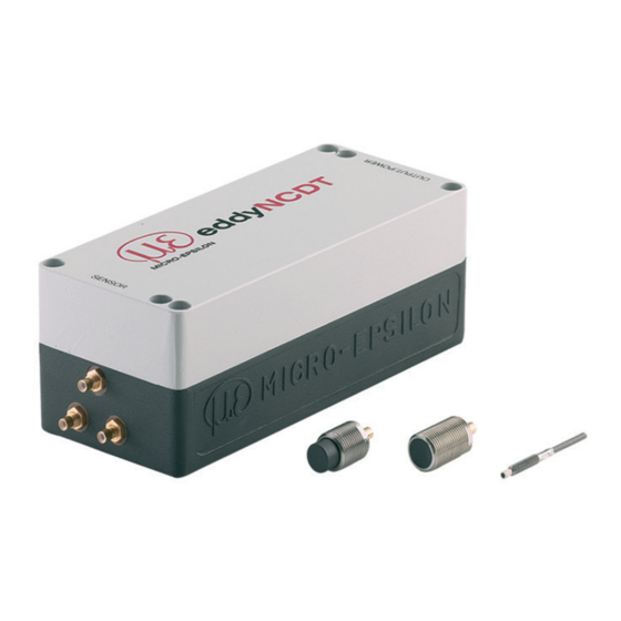
The components are matched. The allocation of the sensor and the controller is determined by the serial number. Voltage supply Signal output Sensor connection Sensors Synchronization input Synchronization output Fig. 1 eddyNCDT 3010 with controller and sensors eddyNCDT 3010 Page 8... -
Page 9: Technical Data
Repeatability μm 0.05 Signal output Standard: 0 ... 10 V / 10 mA and 4 ... 20 mA Power supply 24 VDC (9 ... 30 V) / 205 mA Synchronization With cable SC 30, see Chap. eddyNCDT 3010 Page 9... - Page 10 1) Based on midrange 2) without cable F.S.O. = Full Scale Output MMR = Midrange Measuring systems of the eddyNCDT 3010 series measure targets made of electrically conductive materials. A distinction is made between - non-ferromagnetic materials and - ferromagnetic materials...
-
Page 11: Delivery
You will find optional accessories in appendix, see Chap. Storage - Storage temperature: ƒ Sensor and sensor cable: -50 ... +150 °C (-58 to +302 °F) ƒ Controller: -25 ... +75 °C (-13 to +167 °F) - Humidity: 5 - 95 % (non condensing) eddyNCDT 3010 Page 11... -
Page 12: Commissioning
Shielded sensors, see Fig. 4 - Type designation: S.. - Structure: The sensor is encased up to the top by a steel casing with mounting thread. Radial parts in radial direction are screened. Fig. 4 Shielded sensor eddyNCDT 3010 Page 12... -
Page 13: Sensor Cable
The cables of one type are tuned to the same capacitance at the factory. This may result in deviations in length of +15 % in relation to the nominal length. Do not shorten the tuned cables, because this changes the capacity and the adjustment of the measu- ring system. eddyNCDT 3010 Page 13... -
Page 14: Controller
The controller is already tuned to the delivered sensor with sensor cable at the factory. Voltage supply Signal output Sensor connection Synchronization Input Synchronization Output Fig. 7 Controller DT3010 with connecting elements The power and output cable PC3/8 can be delivered as an accessory, see Chap. eddyNCDT 3010 Page 14... -
Page 15: Synchronization In Multichannel Systems
Commissioning Synchronization in Multichannel Systems Several measuring systems in the eddyNCDT 3010 series can be operated simultaneously as multichannel systems. Synchronization of the measuring systems avoid interference between the sensors. Plug the SC30 synchronization cable, available as an accessory, see Chap. -
Page 16: System Adjustment
Push the sensor through the hole in the sensor support. Screw the sensor tightening the mounting nuts on the thread protruding from the support on both sides. Tighten carefully to avoid damaging the sensors, especially the smaller ones. eddyNCDT 3010 Page 16... - Page 17 Diameter of the sensor mounting plate = twice the diameter of the sensor Fig. 11 Sensor without thread in standard mounting When calibrating, keep the same relative position of the sensor to the support as in the measurement! eddyNCDT 3010 Page 17...
-
Page 18: Flush Assembly
Tighten carefully to avoid damage, especially to smaller sensors. Calibrate the measuring system in the measuring setup with actual mounted sensor. Fig. 12 Example of flush assembly of a shielded sensor in a metal support eddyNCDT 3010 Page 18... -
Page 19: Laying Sensor Cables
Do not kink the cable, the minimum bending radius is 30 mm. Protect the cable against pressure in pressurized rooms. Do not damage the sensor cable. NOTICE - Protect the cable sheath. - Keep the minimum bending radius. > Loss of functionality! eddyNCDT 3010 Page 19... -
Page 20: Operation
0 VDC Power supply (option) Power supply (option) +15 VDC Power supply (option) Fig. 14 Socket pin assignment and signal output for standard supply (+24 VDC) and optional supply (±15 VDC) - view on solder pin side female cable connector eddyNCDT 3010 Page 20... - Page 21 0 Volt green Signal voltage output Inner cable 3-wire with blue 0 Volt screen Signal current output black Outer screen bare Inner screen (connect with Pin 7, blue) Fig. 15 Pin assignment and color codes eddyNCDT 3010 Page 21...
-
Page 22: Control Elements
The measuring signal can be adjusted in the range from 0 V to +10 V at a max. output current of 10 mA. The output is temporarily short-circuit-proof. The output impedance is less than 10 ohms. The controller consists a voltage and current output (4 ... 20 mA). eddyNCDT 3010 Page 22... -
Page 23: Calibration And Linearization
Use the original measuring environment for calibration where possible. Simulate the measuring environ- ment if this is not possible. Connect and synchronize all channels in multichannel systems, see Chap. 4.2. Fig. 17 Micrometer calibration device eddyNCDT 3010 Page 23... - Page 24 The target is at a distance (start of measuring range and 1/2 measuring range) from the sensor. Set the output voltage on the Gain potentiometer to half the value of the desired voltage for full measu- ring range. 1) Output voltage for full measuring range eddyNCDT 3010 Page 24...
- Page 25 Repeat zero, gain and linearity adjustment (steps 1 to 3) until the output voltage reaches the preset value at the three reference points. The highest sensitivity over the whole range is achieved at a calibration to 10 V output voltage. This gives the best signal/noise ratio. eddyNCDT 3010 Page 25...
- Page 26 Zero and Gain adjustment have no effect on the total linearity of the system! The zero can be shifted or the curve steepness changed after linearization. Check calibration after every sensor or sensor cable change. Re-linearize the measuring channel if necessary. eddyNCDT 3010 Page 26...
-
Page 27: Shifting The Output Characteristic
The electrical zero can be shifted later after linearizing the system output and installing the sensor: Shift the electrical zero by about 30 % of the measuring range, see Fig. 20, re-adjust the Zero potentio- meter for this. Zero Distance Fig. 20 Zero shift of calibration curve eddyNCDT 3010 Page 27... -
Page 28: Elimination Errors
Output signal oscillates at low frequency in multi- - Interference between sensors channel mode. Synchronize systems. No change in output signal Check supply voltage. Check allocation of sensor type and cable length. Check sensor and cable. eddyNCDT 3010 Page 28... -
Page 29: Warranty
The warranty period lasts 12 months following the day of shipment. Defective parts, except wear parts, will be repaired or replaced free of charge within this period if you return the device free of cost to MICRO-EPSILON. This warranty does not apply to damage resulting from abuse of the equipment and devices, from forceful handling or installation of the devices or from repair or modifications performed by third parties. -
Page 30: Appendix A 1 Accessories
3 m / 10 ft long, 8-pin with a connec- tor suitable for DT3010 electronics and cable lugs for connection to terminal block SC30 Synchronization cable, length 30 cm, for connecting the electronics to be synchronized ø3 (.12 dia.) eddyNCDT 3010 Page 30... - Page 31 0 - 25 mm, division 2 μm, adjustable zero, for sensors U1 to U15 MC2.5 Micrometer calibration unit; setting range 0 - 2.5 mm, division 0.1 μm, for sensors U05, U1, S1 and CSP2008 Universal controller for two sensor signals eddyNCDT 3010 Page 31...
-
Page 32: A 2 Spare Parts
Sensor cable, length 3 m (±15 %) with straight SMC cable sockets Sensor extension cable, length 3 m (±15 %) with straight SMC cable sockets and connector coupling to give a total length of 6 m eddyNCDT 3010 Page 32... - Page 33 Appendix | Spare Parts Sensor cable, length 6 m (±15 %) with straight SMC cable sockets eddyNCDT 3010 Page 33...
-
Page 34: A 3 Dimensional Drawings
WS 10 (.51) ø12 (0.9 ±0.09 ft) (.39) (.47 dia.) (.79) WS 27 WS 19 (.75) (1.06) M12x1 M18x1 ø9 (.35) WS 10 ø14 (.39) 6 (.24) WS 16 (.55 dia.) (.63) 6 (.24) (.79) (.98) eddyNCDT 3010 Page 34... - Page 35 ø4 (.16 dia.) ø8 (.31) (.79) (.63) 3 m ±0.45 m (.47) (.71) Integrated cable ø4.2 3 Mounting (.17) holes on bolt circle ø20 (.47) Dimensions in mm (inches), not to scale WS = Wrench size eddyNCDT 3010 Page 35...
-
Page 36: A 3.2 Sensor Cable
C3: 3 ±0.45 m (9.8 ±1.5 ft) C6: 6 ±0.9 m (19.7 ± 2.95 ft) (.63) (.79) A 3.3 Controller 150 (5.91) OUTPUT/POWER 138 (5.43) Mounting holes for screws M4 SENSOR SYN IN SYN OUT Dimensions in mm (inches), not to scale eddyNCDT 3010 Page 36... - Page 37 Appendix | Dimensional Drawings eddyNCDT 3010 Page 37...
- Page 38 MICRO-EPSILON MESSTECHNIK GmbH & Co. KG X9751145-B021115HDR Königbacher Str. 15 · 94496 Ortenburg / Germany MICRO-EPSILON MESSTECHNIK Tel. +49 (0) 8542 / 168-0 · Fax +49 (0) 8542 / 168-90 *X9751145-B02* info@micro-epsilon.de · www.micro-epsilon.com...
Need help?
Do you have a question about the eddyNCDT 3010 and is the answer not in the manual?
Questions and answers