Table of Contents
Advertisement
Quick Links
Advertisement
Table of Contents
Troubleshooting

Related Manuals for IBM 7383


Summary of Contents for IBM 7383
- Page 1 System x3500 M4 Type 7383 Installation and Service Guide...
- Page 3 System x3500 M4 Type 7383 Installation and Service Guide...
- Page 4 Appendix D, “Getting help and technical assistance,” on page 449, “Notices” on page 453, the Warranty Information document, and the Safety Information and Environmental Notices and User Guide documents on the IBM Documentation CD. Sixth Edition (May 2013) © Copyright IBM Corporation 2013.
-
Page 5: Table Of Contents
Chapter 1. The IBM System x3500 M4 Installing the microprocessor 2 expansion board . . 77 Type 7383 server ... 1 Installing a microprocessor and heat sink . . 83 The IBM Documentation CD . - Page 6 Updating the Universal Unique Identifier Chapter 5. Parts listing, IBM System (UUID) . 123 x3500 M4 Type 7383 ..173 Updating the DMI/SMBIOS data . . 125 Replaceable server components . . 173 Structural parts .
- Page 7 Getting help and information from the World Wide Removing the 2.5-inch hard disk drive . 450 backplane . 275 How to send DSA data to IBM . 450 Installing the 2.5-inch hard disk drive backplane 277 Creating a personalized support web page . 451 Removing the 3.5-inch hard disk drive...
- Page 8 System x3500 M4 Type 7383: Installation and Service Guide...
-
Page 9: Safety
Ennen kuin asennat tämän tuotteen, lue turvaohjeet kohdasta Safety Information. Avant d'installer ce produit, lisez les consignes de sécurité. Vor der Installation dieses Produkts die Sicherheitshinweise lesen. Prima di installare questo prodotto, leggere le Informazioni sulla Sicurezza. © Copyright IBM Corp. 2013... - Page 10 Les sikkerhetsinformasjonen (Safety Information) før du installerer dette produktet. Antes de instalar este produto, leia as Informações sobre Segurança. Antes de instalar este producto, lea la información de seguridad. Läs säkerhetsinformationen innan du installerar den här produkten. viii System x3500 M4 Type 7383: Installation and Service Guide...
-
Page 11: Guidelines For Trained Service Technicians
Make sure that the insulation is not frayed or worn. 4. Remove the cover. 5. Check for any obvious non-IBM alterations. Use good judgment as to the safety of any non-IBM alterations. 6. Check inside the system for any obvious unsafe conditions, such as metal filings, contamination, water or other liquid, or signs of fire or smoke damage. -
Page 12: Guidelines For Servicing Electrical Equipment
If an electrical accident occurs, use caution, turn off the power, and send another person to get medical aid. System x3500 M4 Type 7383: Installation and Service Guide... -
Page 13: Safety Statements
Safety statements These statements provide the caution and danger information that is used in this documentation. Important: Each caution and danger statement in this documentation is labeled with a number. This number is used to cross reference an English-language caution or danger statement with translated versions of the caution or danger statement in the Safety Information document. - Page 14 Statement 2 CAUTION: When replacing the lithium battery, use only IBM Part Number 33F8354 or an equivalent type battery recommended by the manufacturer. If your system has a module containing a lithium battery, replace it only with the same module type made by the same manufacturer.
- Page 15 DANGER Some laser products contain an embedded Class 3A or Class 3B laser diode. Note the following. Laser radiation when open. Do not stare into the beam, do not view directly with optical instruments, and avoid direct exposure to the beam. Statement 4 ≥...
- Page 16 There are no serviceable parts inside these components. If you suspect a problem with one of these parts, contact a service technician. Statement 11 CAUTION: The following label indicates sharp edges, corners, or joints nearby. Statement 12 System x3500 M4 Type 7383: Installation and Service Guide...
- Page 17 CAUTION: The following label indicates a hot surface nearby. Statement 13 DANGER Overloading a branch circuit is potentially a fire hazard and a shock hazard under certain conditions. To avoid these hazards, ensure that your system electrical requirements do not exceed branch circuit protection requirements. Refer to the information that is provided with your device for electrical specifications.
- Page 18 CAUTION: Do not place any object on top of rack-mounted devices. Statement 27 CAUTION: Hazardous moving parts are nearby. System x3500 M4 Type 7383: Installation and Service Guide...
-
Page 19: Chapter 1. The Ibm System X3500 M4 Type 7383 Server
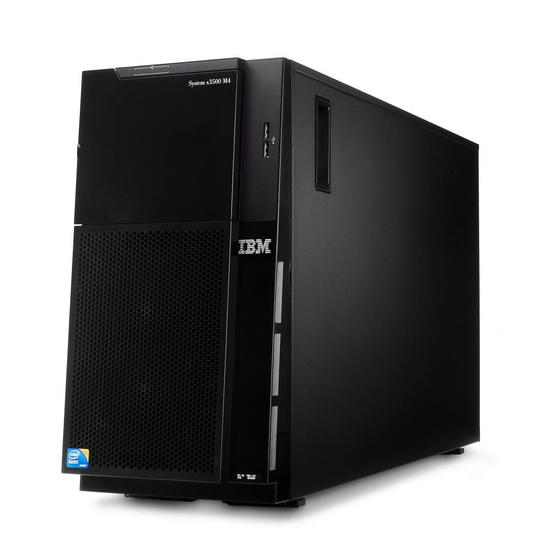
If firmware and documentation updates are available, you can download them from the IBM website. The server might have features that are not described in the documentation that comes with the server, and the documentation might be updated occasionally to include information about those features, or technical 1. - Page 20 Note: The illustrations in this document might differ slightly from your hardware. Figure 1. The front of the server You can download the IBM ServerGuide Setup and Installation CD to help you configure the hardware, install device drivers, and install the operating system.
-
Page 21: The Ibm Documentation Cd
The IBM Documentation CD The IBM Documentation CD contains documentation for the server in Portable Document Format (PDF) and includes the IBM Documentation Browser to help you find information quickly. Hardware and software requirements The hardware and software requirements of the IBM Documentation CD. -
Page 22: Related Documentation
The following documentation also comes with the server: v Warranty Information This document is in printed format and comes with the server. It contains warranty terms and a pointer to the IBM Statement of Limited Warranty on the IBM website. v Important Notices This document is in printed format and comes with the server. -
Page 23: Notices And Statements In This Document
These updates are available from the IBM website. To check for updates, go to http://www.ibm.com/supportportal. Notices and statements in this document The caution and danger statements in this document are also in the multilingual Safety Information document, which is on the IBM Documentation CD. Each statement is numbered for reference to the corresponding statement in your language in the Safety Information document. -
Page 24: Server Features And Specifications
– Slot 4: PCI Express 3.0 x8 quad-rank – Slot 5: PCI Express 3.0 x16 – Registered DIMM (RDIMM), (support 225W GPU) unbuffered DIMM (UDIMM), or load reduced DIMM (LRDIMM) – Slot 6: PCI Express 3.0 x8 System x3500 M4 Type 7383: Installation and Service Guide... - Page 25 “U.” A 1-U-high device is – RAID 5/50 (1 GB Flash) with 4.45 cm (1.75 inches) tall. optional FoD RAID 6/60 and SED upgrade – RAID 5/50 and SED (Zero Cache) Chapter 1. The IBM System x3500 M4 Type 7383 server...
- Page 26 For accordance with ISO 7779 and information about the limits for reported in conformance with ISO particulates and gases, see 9296. “Particulate contamination” on page 455. System x3500 M4 Type 7383: Installation and Service Guide...
-
Page 27: What Your Server Offers
(as the IPMI event log), the integrated management module (IMM) event log (as the ASM event log), and the operating-system event logs. You can send the DSA log as a file to IBM Support or view the information as a text file or HTML file. - Page 28 Light path diagnostics Light path diagnostics provides LEDs to help you diagnose problems. For more information about light path diagnostics and the LEDs, see “Light path diagnostics LEDs” on page 137. System x3500 M4 Type 7383: Installation and Service Guide...
- Page 29 1. You cannot mix 750-watt and 900-watt power supplies in the server. 2. The server is not running in power redundant mode with two 225W GPUs installed, two 900-watt power supplies are required. v Remote presence and blue-screen capture features Chapter 1. The IBM System x3500 M4 Type 7383 server...
- Page 30 Hypervisor is virtualization software that enables multiple operating systems to run on a host system at the same time. Install the USB flash device in the USB embedded hypervisor flash device connectors on System x3500 M4 Type 7383: Installation and Service Guide...
-
Page 31: Reliability, Availability, And Serviceability
Your server has the following RAS features: v 3-year parts and 3-year labor limited warranty (Machine Type 7383) v 24-hour support center v Automatic error retry and recovery... -
Page 32: Ibm Systems Director
A set of common tasks that are included with IBM Systems Director provides many of the core capabilities that are required for basic management, which means instant out-of-the-box business value. -
Page 33: Server Controls, Leds, And Power
Updating installed plug-ins to add new features and functions to the base capabilities v Managing the life cycles of virtual resources For more information about IBM Systems Director, see the IBM Systems Director Information Center at http://publib.boulder.ibm.com/infocenter/director/v6r1x/ index.jsp?topic=/director_6.1/fqm0_main.html, and the Systems Management web page at http://www.ibm.com/systems/management, which presents an overview... - Page 34 This LED is used on hot-swap SAS or SATA hard disk drives. When this LED is lit, it indicates that the drive has failed. If an optional IBM ServeRAID controller is installed in the server, when this LED is flashing slowly (one flash per second), it indicates that the drive is being rebuilt.
-
Page 35: Operator Information Panel
Use this blue LED to visually locate the server among other servers. You can use IBM Systems Director to light this LED remotely. This LED is controlled by the IMM2. When you light the system-locator LED, the LED will blink and it will continue to blink until you turn it off. -
Page 36: Light Path Diagnostics Panel
For more information about the LEDs on the light path diagnostics panel, see “Light path diagnostics LEDs” on page 137. The following illustration shows the LEDs on the light path diagnostics panel. System x3500 M4 Type 7383: Installation and Service Guide... -
Page 37: Rear View
The following illustrations show the connectors and LEDs on the rear of the server. The following illustration shows the connectors on the rear of the server. Figure 5. Rear view of server Chapter 1. The IBM System x3500 M4 Type 7383 server... - Page 38 It allows you to blue screen the server and take a memory dump (use this button only when directed by the IBM service support). You might have to use a pen or the end of a straightened paper clip to press the button.
- Page 39 Power-supply error LED: When the power-supply error LED is lit, it indicates that the power supply has failed. Note: Power supply 1 is the default/primary power supply. If power supply 1 fails, you must replace the power supply immediately. Chapter 1. The IBM System x3500 M4 Type 7383 server...
-
Page 40: Server Power Features
PCI options. 2. When you turn on the server with external graphical adapters installed, the IBM logo displays on the screen after approximately 3 minutes. This is normal operation while the system loads. 3. Make sure the left-side cover is closed. -
Page 41: Turning Off The Server
The integrated management module (IMM) can turn off the server as an automatic response to a critical system failure. v The server turns off when the left-side cover is opened. Chapter 1. The IBM System x3500 M4 Type 7383 server... - Page 42 System x3500 M4 Type 7383: Installation and Service Guide...
-
Page 43: Chapter 2. Installing Optional Devices
In addition to the instructions in this chapter for installing optional hardware devices, updating the firmware and device drivers, and completing the installation, IBM Business Partners must also complete the steps in “Instructions for IBM Business Partners” on page 26. -
Page 44: Instructions For Ibm Business Partners
2. Shut down and restart the server multiple times to ensure that the server is correctly configured and functions correctly with the newly installed devices. 3. Save the DSA log as a file and send it to IBM. For information about transferring data and logs, see “Sending DSA data to IBM.”... -
Page 45: Server Components
Server components The following illustration shows the major components in the server. The illustrations in this document might differ slightly from your hardware. Figure 7. Server components System-board internal connectors The following illustrations show the internal connectors on the system board and the microprocessor 2 expansion board. - Page 46 Figure 8. Internal connectors on system board The following illustration shows the internal connectors on the microprocessor 2 expansion board. Figure 9. Internal connectors on microprocessor 2 expansion board System x3500 M4 Type 7383: Installation and Service Guide...
-
Page 47: System-Board External Connectors
System-board external connectors The following illustration shows the external connectors on the system board. Figure 10. External connectors on system board System-board switches and jumpers The following illustration shows the location and description of the switches and jumpers. Figure 11. Location and description of switches and jumpers Chapter 2. - Page 48 34, “Handling static-sensitive devices” on page 37, and “Turning off the server” on page 23. 2. Any system-board switch or jumper block that is not shown in the illustrations in this document are reserved. System x3500 M4 Type 7383: Installation and Service Guide...
-
Page 49: System-Board Leds And Controls
System-board LEDs and controls The following illustration shows the light-emitting diodes (LEDs) on the system board. Any error LED can be lit after ac power has been removed from the system-board tray so that you can isolate a problem. After ac power has been removed from the system-board tray, power remains available to these LEDs for up to 90 seconds. -
Page 50: Hard Disk Drive Backplane Connectors
Hard disk drive backplane connectors The following illustrations show the connectors on the 2.5-inch and 3.5-inch hard disk drive backplanes and the backplate assembly. Figure 14. Connectors on the 3.5-inch hard disk drive backplane System x3500 M4 Type 7383: Installation and Service Guide... - Page 51 Figure 15. Connectors on the 3.5-inch hard disk drive backplate assembly Figure 16. Connectors on the 2.5-inch hard disk drive backplane Chapter 2. Installing optional devices...
-
Page 52: Installation Guidelines
Figure 17. Connectors on the 2.5-inch hard disk drive backplane with the expander Installation guidelines Use the installation guidelines to install the IBM System x3500 M4 Type 7383. Attention: Static electricity that is released to internal server components when the server is powered-on might cause the system to halt, which might result in the loss of data. - Page 53 working correctly. If the server is not working correctly, see “Running DSA Preboot diagnostic programs” on page 149 for information about how to run diagnostics. v Observe good housekeeping in the area where you are working. Place removed covers and other parts in a safe place. v Do not attempt to lift an object that you think is too heavy for you.
-
Page 54: System Reliability Guidelines
Do not allow your necktie or scarf to hang inside the server. v Remove jewelry, such as bracelets, necklaces, rings, and loose-fitting wrist watches. System x3500 M4 Type 7383: Installation and Service Guide... -
Page 55: Handling Static-Sensitive Devices
v Remove items from your shirt pocket, such as pens and pencils, that could fall into the server as you lean over it. v Avoid dropping any metallic objects, such as paper clips, hairpins, and screws, into the server. Handling static-sensitive devices Use this information to handle static-sensitive devices. - Page 56 4. From inside of the top section of the bezel door, slide the blue tab up to unlock the bezel media door; then, grasp the depressed area on the media door and pull the door open. System x3500 M4 Type 7383: Installation and Service Guide...
-
Page 57: Removing The Left-Side Cover
5. When the media door is unlocked, the icon on the side of the bezel will be in the unlocked position. Removing the left-side cover Use this information to unlock and remove the left-side cover by using the key that comes with the server. Before you begin Important: Before you install optional hardware devices, make sure that the server is working correctly. -
Page 58: Removing The Air Baffle
Attention: Do not allow the server to fall over. 2. Unlock and remove the left-side cover (see “Removing the left-side cover” on page 39). 3. Remove the air baffle from the server and set it aside. System x3500 M4 Type 7383: Installation and Service Guide... -
Page 59: Removing The Fan Cage Assembly
Attention: For proper cooling and airflow, replace the air baffle before you turn on the server. Operating the server with the air baffle removed might damage server components when two microprocessors installed. Removing the fan cage assembly Use this information to remove the fan cage assembly from the server. Before you begin Read the safety information in “Safety”... - Page 60 7. Rotate the fan cage release latch to the open position. The fan cage will lift up slightly when the release latch is fully open. 8. Grasp the fan cage assembly and lift it out of the server. System x3500 M4 Type 7383: Installation and Service Guide...
-
Page 61: Installing A Simple-Swap Fan
Installing a simple-swap fan Use this information to install a simple-swap fan in the server. Before you begin The server comes with two 120 mm x 38 mm simple-swap fans in the fan cage assembly. The following instructions can be used to install any simple-swap fan in the server. - Page 62 Close and fasten the release lever. 5. Open the fan-locking handle on the replacement fan. 6. Insert the fan into the socket and close the handle to the locked position. System x3500 M4 Type 7383: Installation and Service Guide...
-
Page 63: Hard Disk Drive Installation
7. Close the fan cage cover. 8. Install and lock the left-side cover (see “Replacing the left-side cover” on page 98). What to do next If you have other devices to install or remove, do so now. Otherwise, go to “Completing the installation”... - Page 64 Figure 18. Server with eight 2.5-inch hard disk drives System x3500 M4 Type 7383: Installation and Service Guide...
- Page 65 Figure 19. Server with sixteen 2.5-inch hard disk drives Chapter 2. Installing optional devices...
- Page 66 Figure 20. Server with twenty-four 2.5-inch hard disk drives System x3500 M4 Type 7383: Installation and Service Guide...
- Page 67 Figure 21. Server with thirty-two 2.5-inch hard disk drives The following illustrations show the location of the drive bays in the 3.5-inch hot-swap SAS or hot-swap SATA hard disk drive server models. Chapter 2. Installing optional devices...
- Page 68 Figure 22. Server with eight 3.5-inch hard disk drives The following illustrations show the location of the drive bays in the 2.5-inch and 3.5-inch hot-swap SAS or hot-swap SATA hard disk drive server models. System x3500 M4 Type 7383: Installation and Service Guide...
- Page 69 PCI adapter, save the EMC shield and filler panel from the bay or the PCI adapter slot cover in the event that you later remove the drive or adapter. v For a complete list of supported options for the server, see http:// www.ibm.com/systems/info/x86servers/serverproven/compat/us. Chapter 2. Installing optional devices...
-
Page 70: Installing A 2.5-Inch Hot-Swap Hard Disk Drive
5. Make sure that the tray handle is open; then, install the hard disk drive into the hot-swap bay. System x3500 M4 Type 7383: Installation and Service Guide... -
Page 71: Installing A 3.5-Inch Hot-Swap Hard Disk Drive
If the server is configured for RAID operation through an optional ServeRAID adapter, you might have to reconfigure your disk arrays after you install hard disk drives. See the ServeRAID documentation on the IBM ServeRAID Support CD for additional information about RAID operation and complete instructions for using ServeRAID manager. - Page 72 153 for more information. Note: You might have to reconfigure the disk arrays after you install hard disk drives. See the RAID documentation on the IBM website at http://www.ibm.com/supportportal for information about RAID adapters. System x3500 M4 Type 7383: Installation and Service Guide...
-
Page 73: Installing A 3.5-Inch Simple-Swap Hard Disk Drive
What to do next If you have other devices to install or remove, do so now. Otherwise, go to “Completing the installation” on page 94. Installing a 3.5-inch simple-swap hard disk drive Use this information to install a 3.5-inch simple-swap hard disk drive. Before you begin Before installing a 3.5-inch simple-swap hard disk drive, read the following information:... -
Page 74: Installing A Dvd Drive
You have removed the blue optical drive rails from the side of the old drive and have them available for installation on the new drive. Note: If you are installing a drive that contains a laser, observe the following safety precautions. Statement 3 System x3500 M4 Type 7383: Installation and Service Guide... - Page 75 CAUTION: When laser products (such as CD-ROMs, DVD drives, fiber optic devices, or transmitters) are installed, note the following: v Do not remove the covers. Removing the covers of the laser product could result in exposure to hazardous laser radiation. There are no serviceable parts inside the device.
-
Page 76: Installing An Optional Tape Drive
1. Unlock and remove the left-side cover (see “Removing the left-side cover” on page 39). 2. Open the bezel (see “Opening the bezel media door” on page 37). 3. Remove the air baffle if installed (see “Removing the air baffle” on page 210). System x3500 M4 Type 7383: Installation and Service Guide... -
Page 77: Memory Module Installation
(SDRAM) dual inline memory modules (DIMMs) with error correcting code (ECC). See http://www.ibm.com/systems/info/x86servers/serverproven/ compat/us for a list of supported memory modules for the server. – The specifications of a DDR3 DIMM are on a label on the DIMM, in the following format. - Page 78 – When you install 3 RDIMMs per channel, the memory runs at 1066 MHz – All channels in a server run at the fastest common frequency – Do not install registered, unbuffered, and load reduction DIMMs in the same server System x3500 M4 Type 7383: Installation and Service Guide...
- Page 79 v The maximum memory speed is determined by the combination of the microprocessor, DIMM speed, DIMM type, Operating Modes in UEFI settings, and the number of DIMMs installed in each channel. ™ v In two-DIMM-per-channel configuration, a server with an Intel Xeon E5-2600 series microprocessor automatically operates with a maximum memory speed of up to 1600 MHz when the following condition is met:...
- Page 80 2; you do not have to wait until all of the DIMM slots for microprocessor 1 are filled. The following illustration shows the location of the DIMM connectors on they system board. Figure 24. The location of the DIMM connectors on the system board System x3500 M4 Type 7383: Installation and Service Guide...
-
Page 81: Dimm Installation Sequence
DIMM installation sequence Depending on the server model, the server may come with a minimum of one 2 GB or 4 GB DIMM installed in slot 1. When you install additional DIMMs, install them in the order shown in the following table to optimize system performance. In general, all three channels on the memory interface for each microprocessor can be populated in any order and have no matching requirements. -
Page 82: Memory Rank Sparing
Note: You can install DIMMs for the microprocessor 2 once the microprocessor 2 is installed. You do not need to wait until all of the DIMM connectors for microprocessor 1 are filled. System x3500 M4 Type 7383: Installation and Service Guide... -
Page 83: Installing A Dimm
The following table shows the installation sequence for memory rank sparing mode: Table 7. Memory rank sparing mode DIMM population sequence Number of installed Number of DIMMs microprocessor DIMM connector First pair of DIMMs 1, 2 Second pair of DIMMs 4, 5 Third pair of DIMMs 8, 9... - Page 84 7. Firmly press the DIMM straight down into the connector by applying pressure on both ends of the DIMM simultaneously. The retaining clips snap into the locked position when the DIMM is firmly seated in the connector. System x3500 M4 Type 7383: Installation and Service Guide...
-
Page 85: Installing A Pci-X Bracket
Note: If there is a gap between the DIMM and the retaining clips, the DIMM has not been correctly inserted; open the retaining clips, remove the DIMM, and then reinsert it. What to do next If you have other devices to install or remove, do so now. Otherwise, go to “Completing the installation”... - Page 86 Attention: Incomplete insertion might cause damage to the system board or the adapter. 8. Make sure the latch on the side of the PCI-X bracket is secured to the rear of the server chassis. System x3500 M4 Type 7383: Installation and Service Guide...
- Page 87 9. Install the screw that secures the PCI-X bracket to the server. What to do next If you have other devices to install or remove, do so now. Otherwise, go to “Completing the installation” on page 94. Chapter 2. Installing optional devices...
-
Page 88: Installing An Adapter
To avoid this potential problem, always use an electrostatic-discharge wrist strap or other grounding system when working inside the server with the power on. Read the safety information in “Safety” on page vii and “Installation guidelines” on page 34. System x3500 M4 Type 7383: Installation and Service Guide... - Page 89 If you are replacing a component or installing an optional device in the server, you need to turn off the server and peripheral devices, and disconnect the power cords and all external cables. About this task To install an adapter, complete the following steps. Procedure 1.
-
Page 90: Installing An Adapter On The Pci-X Bracket
To install an adapter on the PCI-X bracket, complete the following steps. Procedure 1. Carefully turn the server on its side so that it is lying flat, with the cover facing System x3500 M4 Type 7383: Installation and Service Guide... - Page 91 Attention: Do not allow the server to fall over. 2. Unlock and remove the left-side cover (see “Removing the left-side cover” on page 39). 3. See the documentation that comes with the adapter for any cabling instructions and information about jumper or switch settings. (It might be easier for you to route cables before you install the adapter.) 4.
-
Page 92: Installing An Optional Serveraid Adapter Memory Module
What to do next If you have other devices to install or remove, do so now. Otherwise, go to “Completing the installation” on page 94. System x3500 M4 Type 7383: Installation and Service Guide... -
Page 93: Installing A Raid Adapter Battery Or Flash Power Module Remotely In The Server
Installing a RAID adapter battery or flash power module remotely in the server Use this information to install a RAID adapter battery or flash power module remotely in the server. Before you begin Note: When you install any RAID adapter that comes with batteries, it is sometimes necessary to install the batteries in another location in the server to prevent the batteries from overheating. - Page 94 Align the battery/flash power module cable connector with the slot on the battery/flash power module holder. Place the battery/flash power module into the battery/flash power module holder and make sure that the battery/flash power module holder engages the battery/flash power module securely. System x3500 M4 Type 7383: Installation and Service Guide...
-
Page 95: Installing The Microprocessor 2 Expansion Board
Note: The positioning of the remote battery/flash power module depends on the type of the remote batteries/flash power module that you install. b. Connect the other end of the battery/flash power module cable to the battery/flash power module cable connector on the battery/flash power module. - Page 96 Slide the side bracket toward the rear of the server. c. Fasten the thumbscrew on the side bracket. 6. Install the two guide pins on the system board. System x3500 M4 Type 7383: Installation and Service Guide...
- Page 97 7. Remove the cover on the microprocessor 2 expansion board connector from the system board. 8. Make sure the microprocessor 2 expansion board release lever is in the open position. 9. Align the microprocessor 2 expansion board to the guide pins on the bottom of the chassis and the side bracket.
- Page 98 10. Align the holes on the microprocessor 2 expansion board to the guide pins on the system board. Install the microprocessor 2 expansion board on the system board. 11. Press the microprocessor 2 expansion board firmly and horizontally to the system board. System x3500 M4 Type 7383: Installation and Service Guide...
- Page 99 Note: a. Static electricity that is released to internal server components when the server is powered-on might cause the server to halt, which might result in the loss of data. To avoid this potential problem, always use an electrostatic-discharge wrist strap or other grounding system when you work inside the server with the power on.
- Page 100 Note: You might need to install the air baffle before connecting the power cable. What to do next If you have other devices to install or remove, do so now. Otherwise, go to “Completing the installation” on page 94. System x3500 M4 Type 7383: Installation and Service Guide...
-
Page 101: Installing A Microprocessor And Heat Sink
The server supports certain Intel Xeon scalable multi-core microprocessors, which are designed for the LGA 2011 socket. These microprocessors are 64-bit dual-core or quad-core microprocessors with an integrated memory controller, quick-path interconnect, and shared last cache. See http://www.ibm.com/ systems/info/x86servers/serverproven/compat/us for a list of supported microprocessors. - Page 102 Do not remove the first microprocessor from the system board to install the second microprocessor. v To order an additional optional microprocessor, contact your IBM sales representative or IBM reseller. Read the safety information in “Safety” on page vii and “Installation guidelines”...
- Page 103 a. Identify which release lever is labeled as the first release lever to open and open it. b. Open the second release lever on the microprocessor socket. c. Open the microprocessor retainer. Attention: Do not touch the connectors on the microprocessor and the microprocessor socket.
- Page 104 7. Remove the microprocessor socket dust cover, tape, or label from the surface of the microprocessor socket, if one is present. Store the socket cover in a safe place. System x3500 M4 Type 7383: Installation and Service Guide...
- Page 105 Attention: When you handle static-sensitive devices, take precautions to avoid damage from static electricity. For details about handling these devices, see (“Handling static-sensitive devices” on page 37). 8. Close the microprocessor socket release levers and retainer: a. Close the microprocessor retainer on the microprocessor socket. b.
- Page 106 10. If you installed the second microprocessor, install the air baffle (see “Replacing the air baffle” on page 97) and fan 2 (see “Installing a simple-swap fan” on page 259). System x3500 M4 Type 7383: Installation and Service Guide...
-
Page 107: Thermal Grease
What to do next If you have other devices to install or remove, do so now. Otherwise, go to “Completing the installation” on page 94. Thermal grease The thermal grease must be replaced whenever the heat sink has been removed from the top of the microprocessor and is going to be reused or when debris is found in the grease. -
Page 108: Installing A Hot-Swap Power Supply
Before you install an additional power supply or replace a power supply with one of a different wattage, you may use the IBM Power Configurator utility to determine current system power consumption. For more information and to download the utility, go to http://www.ibm.com/systems/bladecenter/ resources/powerconfig.html. - Page 109 Statement 8 CAUTION: Never remove the cover on a power supply or any part that has the following label attached. Hazardous voltage, current, and energy levels are present inside any component that has this label attached. There are no serviceable parts inside these components.
- Page 110 7. If you are replacing a power supply with one of a different wattage, apply the power information label provided with the new power supply over the existing power information label on the server. System x3500 M4 Type 7383: Installation and Service Guide...
-
Page 111: Installing A Usb Embedded Hypervisor Flash Device
8. If you are adding a power supply to the server, attach the redundant power information label that comes with this option on the server cover near the power supplies. Installing a USB embedded hypervisor flash device Use this information to install a USB embedded hypervisor flash device. Before you begin Read the safety information in “Safety”... -
Page 112: Completing The Installation
3. If you removed the server cover, replace it (see “Replacing the left-side cover” on page 98). 4. Reconnect the cables and power cords (see “Connecting the cables” on page 99). System x3500 M4 Type 7383: Installation and Service Guide... -
Page 113: Replacing The Fan Cage Assembly
8. Start the server. Confirm that it starts correctly and recognizes the newly installed devices, and make sure that no error LEDs are lit. 9. (IBM Business Partners only) Complete the additional steps in “Instructions for IBM Business Partners” on page 26. - Page 114 4. Fasten the thumb screw on the fan cage release latch. 5. Connect the fan cage assembly power cable to the system board (see “Internal cable routing and connectors” on page 186). System x3500 M4 Type 7383: Installation and Service Guide...
-
Page 115: Replacing The Air Baffle
Replacing the air baffle Use this information to replace the air baffle. Before you begin Note: When you install the second microprocessor, you must also install fan 2 and the air baffle that come with the second microprocessor upgrade kit. Read the safety information in “Safety”... -
Page 116: Replacing The Left-Side Cover
2. Rotate the top edge of the cover toward the server and press inward on the cover until it clicks into place. 3. Lock the cover, using the key that comes with the server. System x3500 M4 Type 7383: Installation and Service Guide... -
Page 117: Connecting The Cables
Connecting the cables Use this information to connect the cables. About this task The following illustration shows the locations of the input and output connectors on the front of the server. Figure 27. Front of server The following illustration shows the locations of the input and output connectors on the rear of the server. -
Page 118: Updating The Server Configuration
RAID adapter for information about reconfiguring the disk arrays. For information about configuring the Ethernet controller, see “Configuring the Ethernet controller” on page 120. System x3500 M4 Type 7383: Installation and Service Guide... -
Page 119: Chapter 3. Configuration Information And Instructions
The firmware for the server is periodically updated and is available for download on the IBM website. To check for the latest level of firmware, such as the UEFI firmware, device drivers, and integrated management module (IMM) firmware, go to http://www.ibm.com/support/fixcentral. -
Page 120: Configuring The Server
Remote presence capability and blue-screen capture The remote presence and blue-screen capture features are integrated functions of the integrated management module (IMM2). The remote presence feature provides the following functions: System x3500 M4 Type 7383: Installation and Service Guide... - Page 121 UEFI settings from the command line without the need to restart the server to run the Setup utility. For more information about using this program, see “IBM Advanced Settings Utility program” on page 121. v Configuring RAID arrays For information about configuring RAID arrays, see “Configuring RAID arrays”...
-
Page 122: Using The Serverguide Setup And Installation Cd
1. For more information about the Human Interface Infrastructure (HII) and SAS2IRCU, go to http://www.ibm.com/support/entry/portal/ docdisplay?lndocid=MIGR-5088601. 2. For more information about the MegaRAID, go to http://www.ibm.com/ support/entry/portal/docdisplay?lndocid=MIGR-5073015. Using the ServerGuide Setup and Installation CD Use this information as an overview for using the ServerGuide Setup and Installation CD. -
Page 123: Setup And Configuration Overview
When you use the ServerGuide Setup and Installation CD, you do not need setup diskettes. You can use the CD to configure any supported IBM server model. The setup program provides a list of tasks that are required to set up your server model. -
Page 124: Installing Your Operating System Without Using Serverguide
Setup utility menu. If you do not type the administrator password, a limited Setup utility menu is available. 3. Select settings to view or change. System x3500 M4 Type 7383: Installation and Service Guide... -
Page 125: Setup Utility Menu Choices
Setup utility menu choices Use the Setup utility main menu to view and configure server configuration data and settings. The following choices are on the Setup utility main menu for the UEFI. Depending on the version of the firmware, some menu choices might differ slightly from these descriptions. - Page 126 POST Watchdog Timer Select this choice to view or enable the POST watchdog timer. v POST Watchdog Timer Value Select this choice to view or set the POST loader watchdog timer value. System x3500 M4 Type 7383: Installation and Service Guide...
- Page 127 v Reboot System on NMI Select this choice to enable or disable restarting the system whenever a nonmaskable interrupt (NMI) occurs. Enable is the default. v Halt on Severe Error Select this choice to enable or disable the system from booting into OS, displaying the POST event viewer whenever a severe error was detected.
- Page 128 Select this choice to exit from the Setup utility. If you have not saved the changes that you have made in the settings, you are asked whether you want to save the changes or exit without saving them. System x3500 M4 Type 7383: Installation and Service Guide...
-
Page 129: Passwords
Passwords From the User Security menu choice, you can set, change, and delete a power-on password and an administrator password. The User Security menu choice is on the full Setup utility menu only. If you set only a power-on password, you must type the power-on password to complete the system startup and to have access to the full Setup utility menu. - Page 130 You can then start the Setup utility and reset the power-on password. You do not have to return the switch to the previous position. The power-on password override switch does not affect the administrator password. System x3500 M4 Type 7383: Installation and Service Guide...
-
Page 131: Using The Boot Manager
Administrator password: If an administrator password is set, you must type the administrator password for access to the full Setup utility menu. You can use any combination of 6 to 20 printable ASCII characters for the password. Attention: If you set an administrator password and then forget it, there is no way to change, override, or remove it. -
Page 132: The Updatexpress System Pack Installer
What to do next Attention: If you set an administrator password and then forget it, there is no way to change, override, or remove it. You must replace the system board. System x3500 M4 Type 7383: Installation and Service Guide... -
Page 133: Using The Integrated Management Module
Using the integrated management module The integrated management module (IMM) is a second generation of the functions that were formerly provided by the baseboard management controller hardware. It combines service processor functions, video controller, and remote presence function in a single chip. The IMM supports the following basic systems-management features: v Active Energy Manager. -
Page 134: Using The Remote Presence And Blue-Screen Capture Features
The blue-screen capture feature captures the video display contents before the IMM restarts the server when the IMM detects an operating-system hang condition. A system administrator can use the blue-screen capture to assist in determining the cause of the hang condition. System x3500 M4 Type 7383: Installation and Service Guide... -
Page 135: Obtaining The Imm Host Name
Obtaining the IMM host name Use this information to obtain the IMM host name. About this task If you are logging on to the IMM for the first time after installation, the IMM defaults to DHCP. If a DHCP server is not available, the IMM uses a static IP address of 192.168.70.125. -
Page 136: Logging On To The Web Interface
By default, the icmp packet is blocked by Windows firewall. The IMM GUI will then change to “OS booted” status after you change the setting as indicated above in both the Web and CLI interfaces. System x3500 M4 Type 7383: Installation and Service Guide... -
Page 137: Using The Embedded Hypervisor
Using the embedded hypervisor The VMware ESXi embedded hypervisor software is available on the optional IBM USB flash device with embedded hypervisor. About this task The USB flash device can be installed in USB connectors on the system board (see “Internal cable routing and connectors”... -
Page 138: Configuring The Ethernet Controller
Channel over Ethernet (FCoE) and iSCSI storage protocols that is integrated in the integrated management module. For more information and instructions for activating the Features on Demand Ethernet software key, see the IBM Features on Demand User’s Guide. To download the document, go to /http://www.ibm.com/ systems/x/fod/, log in, and click Help. -
Page 139: Ibm Advanced Settings Utility Program
Use this information to update the IBM Systems Director. About this task If you plan to use IBM Systems Director to manage the server, you must check for the latest applicable IBM Systems Director updates and interim fixes. Note: Changes are made periodically to the IBM website. The actual procedure might vary slightly from what is described in this document. -
Page 140: Installing A Newer Version
1. Check for the latest version of IBM Systems Director: a. Go to http://www.ibm.com/systems/software/director/resources.html. b. If a newer version of IBM Systems Director than what comes with the server is shown in the drop-down list, follow the instructions on the web page to download the latest version. -
Page 141: Updating The Universal Unique Identifier (Uuid)
The ASU is an online tool that supports several operating systems. Make sure that you download the version for your operating system. You can download the ASU from the IBM Web site. To download the ASU and update the UUID, complete the following steps. - Page 142 See the Advanced Settings Utility Users Guide for more details. You can access the ASU Users Guide from the IBM website. Note: Changes are made periodically to the IBM website. The actual procedure might vary slightly from what is described in this document.
-
Page 143: Updating The Dmi/Smbios Data
UEFI-based server. The ASU is an online tool that supports several operating systems. Make sure that you download the version for your operating system. You can download the ASU from the IBM website. To download the ASU and update the DMI, complete the following steps. - Page 144 IMM using the online authenticated LAN access method, ASU will automatically use the unauthenticated KCS access method. The following commands are examples of using the userid and password default values and not using the default values: System x3500 M4 Type 7383: Installation and Service Guide...
- Page 145 ASU provides the corresponding mapping layer. To download the Advanced Settings Utility Users Guide, complete the following steps: Note: Changes are made periodically to the IBM website. The actual procedure might vary slightly from what is described in this document. a. Go to http://www.ibm.com/supportportal.
- Page 146 You can also build a bootable media using the applications available through the ToolsCenter website at http://www.ibm.com/support/entry/portal/ docdisplay?lndocid=TOOL-CENTER. From the IBM ToolsCenter page, scroll down for the available tools. 5. Restart the server. System x3500 M4 Type 7383: Installation and Service Guide...
-
Page 147: Chapter 4. Troubleshooting
Diagnosing a problem Before you contact IBM or an approved warranty service provider, follow these procedures in the order in which they are presented to diagnose a problem with your server. - Page 148 UpdateXpress System Pack contains an integration-tested bundle of online firmware and device-driver updates for your server. In addition, you can use IBM ToolsCenter Bootable Media Creator to create bootable media that is suitable for applying firmware updates and running preboot diagnostics.
-
Page 149: Undocumented Problems
Problem determination information is available for many devices such as RAID and network adapters. For problems with operating systems or IBM software or devices, go to http://www.ibm.com/supportportal. 7. Check for troubleshooting procedures and RETAIN tips. Troubleshooting procedures and RETAIN tips document known problems and suggested solutions. -
Page 150: Service Bulletins
Service bulletins IBM continually updates the support website with the latest tips and techniques that you can use to solve problem that you might have with the IBM System x3500 M4 server. To find service bulletins that are available for the IBM IBM System x3500 M4 server, go to and search for 7383, and retain. -
Page 151: Performing The Checkout Procedure
Check the power supply LEDs (see “Power-supply LEDs” on page 142). b. Turn off the server and all external devices. c. Check all internal and external devices for compatibility at http://www.ibm.com/systems/info/x86servers/serverproven/compat/us. d. Check all cables and power cords. e. Set all display controls to the middle positions. -
Page 152: Diagnostic Tools
Integrated Management Module II User's Guide at http://www.ibm.com/ support/entry/portal/docdisplay?lndocid=migr-5086346. v IBM Dynamic System Analysis Two editions of IBM Dynamic System Analysis (DSA) are available for diagnosing problems, DSA Portable and DSA Preboot: – DSA Portable DSA Portable collects and analyzes system information to aid in diagnosing server problems. - Page 153 (IMM) event log (as the ASM event log), and the operating-system event logs. You can send the DSA log as a file to IBM Support (when requested by IBM Support) or view the information as a text file or HTML file.
-
Page 154: Light Path Diagnostics
If an action step is preceded by “(Trained technician only)”, that step must be performed only by a trained technician. v Go to the IBM support website at http://www.ibm.com/supportportal to check for technical information, hints, tips, and new device drivers or to submit a request for information. -
Page 155: Light Path Diagnostics Leds
If an action step is preceded by “(Trained technician only)”, that step must be performed only by a trained technician. v Go to the IBM support website at http://www.ibm.com/supportportal to check for technical information, hints, tips, and new device drivers or to submit a request for information. - Page 156 5. Make sure that the fan on the adapter and the network adapter is seated correctly. If it has failed, replace the failing component. 6. If the failure remains, go to http://www.ibm.com/ supportportal. System x3500 M4 Type 7383: Installation and Service Guide...
- Page 157 2. (Trained technician only) Replace the failing microprocessor (see “Installing a microprocessor and heat sink” on page 319). 3. If the failure remains, go to http://www.ibm.com/ supportportal. Microprocessor + Configuration If the Configuration LED and the Microprocessor LED are...
- Page 158 1. Add a second power supply. 2. Replace the failed power supply. 3. Remove the optional devices. System x3500 M4 Type 7383: Installation and Service Guide...
- Page 159 LEDs and the information in the system-event logs, remove one component at a time; and restart the server after each component is removed. 4. If the failure remains, go to http://www.ibm.com/ supportportal. A nonmaskable interrupt has 1. Check the system-event logs for information about the occurred, or the NMI button was error (see “Event logs”...
-
Page 160: Power-Supply Leds
1. Make sure that the power cord is power when a second connected to a functioning power ‐supply. power supply is source. providing power to 2. Replace the power supply. the server. System x3500 M4 Type 7383: Installation and Service Guide... -
Page 161: System Pulse Leds
Table 12. Power-supply LEDs (continued) AC Power-supply LEDs Error Description Action Notes Faulty power Replace the power supply. supply Faulty power Replace the power supply. supply Power supply Typically indicates 1. Reseat the power supply. not fully seated, that a power supply 2. -
Page 162: Event Logs
You can view the DSA event log through the DSA program (see “Viewing event logs without restarting the server” on page 145). For more information about DSA and DSA messages, see “IBM Dynamic System Analysis” on page 147 and Appendix B, “DSA messages,” on page 361. -
Page 163: Viewing Event Logs Through The Setup Utility
DSA Preboot to view these logs, although you must restart the server to use DSA Preboot. To install DSA Portable or check for and download a later version of DSA Preboot CD image, go to http://www.ibm.com/support/entry/ portal/docdisplay?lndocid=SERV-DSA. If IPMItool is installed in the server, you can use it to view the system-event log. -
Page 164: Clearing The Event Logs
Run DSA Portable to view the diagnostic event log (requires IPMI driver) or create an output file that you can send to IBM service and support (using ftp or local copy). v Use IPMItool to view the system-event log (requires IPMI driver). -
Page 165: Uefi/Post
If POST detects a problem, an error message is sent to the POST event log, see “Event logs” on page 144 for more information. IBM Dynamic System Analysis IBM Dynamic System Analysis (DSA) collects and analyzes system information to aid in diagnosing server problems. DSA collects the following information about the server:... -
Page 166: Dsa Editions
It is provided in the flash memory on the server, or you can create a bootable media such as a CD, DVD, ISO, USB, or PXE using the IBM ToolsCenter Bootable Media Creator (BoMC). For more details, see the BoMC User Guide at http://www.ibm.com/support/entry/portal/... -
Page 167: Running Dsa Preboot Diagnostic Programs
Running DSA Preboot diagnostic programs Use this information to run the DSA Preboot diagnostic programs. About this task Note: The DSA memory test might take up to 30 minutes to run. If the problem is not a memory problem, skip the memory test. To run the DSA Preboot diagnostic programs, complete the following steps: Procedure 1. -
Page 168: Diagnostic Text Messages
If you are running the DSA interactive menu (CLI), type :x to exit the Execute Tests menu; then, select completed tests to view the results. Results You can also send the DSA error log to IBM support to aid in diagnosing the server problems. Automated service request (call home) IBM provides tools that can automatically collect and send data or call IBM Support when an error is detected. -
Page 169: Ibm Electronic Service Agent
IBM Support. You can also choose to collect data manually. It uses minimal system resources, and can be downloaded from the IBM website. For more information and to download IBM Electronic Service Agent, go to http://www.ibm.com/support/ electronic/portal/. -
Page 170: Cd/Dvd Drive Problems
If an action step is preceded by “(Trained technician only)”, that step must be performed only by a Trained technician. v Go to the IBM support website at http://www.ibm.com/supportportal to check for technical information, hints, tips, and new device drivers or to submit a request for information. -
Page 171: Hard Disk Drive Problems
If an action step is preceded by “(Trained technician only)”, that step must be performed only by a trained technician. v Go to the IBM support website at http://www.ibm.com/supportportal to check for technical information, hints, tips, and new device drivers or to submit a request for information. -
Page 172: Hypervisor Problems
If an action step is preceded by “(Trained technician only)”, that step must be performed only by a trained technician. v Go to the IBM support website at http://www.ibm.com/supportportal to check for technical information, hints, tips, and new device drivers or to submit a request for information. -
Page 173: Keyboard, Mouse, Or Usb-Device Problems
If an action step is preceded by “(Trained technician only)”, that step must be performed only by a trained technician. v Go to the IBM support website at http://www.ibm.com/supportportal to check for technical information, hints, tips, and new device drivers or to submit a request for information. -
Page 174: Memory Problems
If an action step is preceded by “(Trained technician only)”, that step must be performed only by a trained technician. v Go to the IBM support website at http://www.ibm.com/supportportal to check for technical information, hints, tips, and new device drivers or to submit a request for information. - Page 175 If an action step is preceded by “(Trained technician only)”, that step must be performed only by a trained technician. v Go to the IBM support website at http://www.ibm.com/supportportal to check for technical information, hints, tips, and new device drivers or to submit a request for information.
-
Page 176: Microprocessor Problems
If an action step is preceded by “(Trained technician only)”, that step must be performed only by a trained technician. v Go to the IBM support website at http://www.ibm.com/supportportal to check for technical information, hints, tips, and new device drivers or to submit a request for information. - Page 177 If an action step is preceded by “(Trained technician only)”, that step must be performed only by a trained technician. v Go to the IBM support website at http://www.ibm.com/supportportal to check for technical information, hints, tips, and new device drivers or to submit a request for information.
-
Page 178: Network Connection Problems
If an action step is preceded by “(Trained technician only)”, that step must be performed only by a trained technician. v Go to the IBM support website at http://www.ibm.com/supportportal to check for technical information, hints, tips, and new device drivers or to submit a request for information. - Page 179 If an action step is preceded by “(Trained technician only)”, that step must be performed only by a trained technician. v Go to the IBM support website at http://www.ibm.com/supportportal to check for technical information, hints, tips, and new device drivers or to submit a request for information.
-
Page 180: Power Problems
If an action step is preceded by “(Trained technician only)”, that step must be performed only by a trained technician. v Go to the IBM support website at http://www.ibm.com/supportportal to check for technical information, hints, tips, and new device drivers or to submit a request for information. -
Page 181: Serial Port Problems
If an action step is preceded by “(Trained technician only)”, that step must be performed only by a trained technician. v Go to the IBM support website at http://www.ibm.com/supportportal to check for technical information, hints, tips, and new device drivers or to submit a request for information. -
Page 182: Serverguide Problems
If an action step is preceded by “(Trained technician only)”, that step must be performed only by a trained technician. v Go to the IBM support website at http://www.ibm.com/supportportal to check for technical information, hints, tips, and new device drivers or to submit a request for information. -
Page 183: Software Problems
If an action step is preceded by “(Trained technician only)”, that step must be performed only by a trained technician. v Go to the IBM support website at http://www.ibm.com/supportportal to check for technical information, hints, tips, and new device drivers or to submit a request for information. -
Page 184: Universal Serial Bus (Usb) Port Problems
If an action step is preceded by “(Trained technician only)”, that step must be performed only by a trained technician. v Go to the IBM support website at http://www.ibm.com/supportportal to check for technical information, hints, tips, and new device drivers or to submit a request for information. -
Page 185: Solving Ethernet Controller Problems
Solving Ethernet controller problems Use this information to solve the Ethernet controller problems. About this task The method that you use to test the Ethernet controller depends on which operating system you are using. See the operating-system documentation for information about Ethernet controllers, and see the Ethernet controller device-driver readme file. -
Page 186: Solving Undetermined Problems
If you suspect a networking problem and the server passes all the system tests, suspect a network cabling problem that is external to the server. System x3500 M4 Type 7383: Installation and Service Guide... -
Page 187: Problem Determination Tips
Because of the variety of hardware and software combinations that can encounter, use the following information to assist you in problem determination. If possible, have this information available when requesting assistance from IBM. v Machine type and model v Microprocessor or hard disk drive upgrades v Failure symptom –... -
Page 188: Recovering The Server Firmware (Uefi Update Failure)
6. Reinstall the server cover; then, reconnect all power cords. 7. Restart the server. The system begins the power-on self-test (POST). 8. Boot the server to an operating system that is supported by the firmware update package that you downloaded. System x3500 M4 Type 7383: Installation and Service Guide... -
Page 189: In-Band Automated Boot Recovery Method
20. Reconnect the power cord and any cables that you removed. 21. Restart the server. The system begins the power-on self-test (POST). 22. If these recovery efforts fail, contact your IBM service representative for support. In-band automated boot recovery method This section details the in-band automated boot recovery method. -
Page 190: Out-Of-Band Method
To specify the number of consecutive restart attempts that will trigger the Nx-boot failure feature, in the Setup utility, click System Settings > Recovery > POST Attempts > POST Attempts Limit. The available options are 3, 6, 9, and 255 (disable Nx-boot failure). System x3500 M4 Type 7383: Installation and Service Guide... -
Page 191: Chapter 5. Parts Listing, Ibm System X3500 M4 Type 7383
See “Structural parts” on page 178 for the list of structural parts. v Tier 1 customer replaceable unit (CRU): Replacement of Tier 1 CRUs is your responsibility. If IBM installs a Tier 1 CRU at your request, you will be charged for the installation. - Page 192 Hard disk drive, 3.5-inch hot-swap, 500 GB, 7.2 K, NL SATA 81Y9787 Hard disk drive, 3.5-inch hot-swap, 2 TB, 7.2 K, NL SATA 81Y9795 Hard disk drive, 3.5-inch hot-swap, 1 TB, 7.2 K, NL SAS 90Y8568 System x3500 M4 Type 7383: Installation and Service Guide...
- Page 193 ServeRAID M5100 series 1 GB cache (RAID 5 upgrade) 46C9029 Microprocessor 2 expansion board 00W2047 Heat sink assembly 94Y7740 Microprocessor, Intel Xeon E5-2690, 2.90 GHz, 20 MB, 1600 MHz, 135 49Y8115 W (8 core) Chapter 5. Parts listing, IBM System x3500 M4 Type 7383...
- Page 194 49Y1565 Memory, 4 GB dual-rank 1.5 V, DDR3, 1600MHz, RDIMM 90Y3180 Memory, 4 GB single-rank 1.5 V, DDR3, 1600MHz, RDIMM 49Y1561 Memory, 8 GB dual-rank 1.5 V, DDR3, 1600MHz, RDIMM 90Y3111 System x3500 M4 Type 7383: Installation and Service Guide...
- Page 195 Cable, line cord 39M5206 Cable, SAS 820 mm 81Y6674 Cable, backplane connection, 2.5-inch 81Y7514 Cable, fan cage assembly 81Y7533 Cable, SATA optical power 81Y7535 Cable, SATA backplate assembly, 3.5-inch 81Y7536 Chapter 5. Parts listing, IBM System x3500 M4 Type 7383...
-
Page 196: Structural Parts
00D2706 Structural parts Structural parts are not covered by the IBM Statement of Limited Warranty. You can place an order on the structural parts from the IBM retail store. The following structural parts are available for purchase from the retail store. -
Page 197: Power Cords
To avoid electrical shock, always use the power cord and plug with a properly grounded outlet. IBM power cords used in the United States and Canada are listed by Underwriter's Laboratories (UL) and certified by the Canadian Standards Association (CSA). - Page 198 Peru, Philippines, Saudi Arabia, Thailand, Taiwan, United States of America, Venezuela 39M5076 United States of America 39M5512 39M5463 Taiwan 39M5087 Thailand 39M5219 Korea (Democratic People’s Republic of), Korea (Republic of) 39M5199 Japan 39M5068 Argentina, Paraguay, Uruguay System x3500 M4 Type 7383: Installation and Service Guide...
- Page 199 Power cord part number Used in these countries and regions 39M5226 India 39M5240 Brazil 39M5241 39M5375 Canada, Germany, United States of America 39M5378 39M5509 Chapter 5. Parts listing, IBM System x3500 M4 Type 7383...
- Page 200 System x3500 M4 Type 7383: Installation and Service Guide...
-
Page 201: Chapter 6. Removing And Replacing Components
IBM to install it, at no additional charge, under the type of warranty service that is designated for your server. See Chapter 5, “Parts listing, IBM System x3500 M4 Type 7383,” on page 173 to determine whether a component is a structural part, Tier 1 CRU, or Tier 2 CRU. - Page 202 4. From inside of the top section of the bezel door, slide the blue tab up to unlock the bezel media door; then, grasp the depressed area on the media door and pull the door open. System x3500 M4 Type 7383: Installation and Service Guide...
-
Page 203: Closing The Bezel Media Door
5. When the media door is unlocked, the icon on the side of the bezel will be in the unlocked position. Closing the bezel media door Use this information to close the bezel media door. Before you begin Read the safety information in “Safety” on page vii and “Installation guidelines” on page 34. -
Page 204: Internal Cable Routing And Connectors
The following illustration shows the power cable routing and the connectors from the power paddle card to the system board and the microprocessor 2 expansion board. Figure 33. Power cable routing in the system board and the microprocessor 2 expansion board System x3500 M4 Type 7383: Installation and Service Guide... -
Page 205: Operator Information Panel Cable Connection
Operator information panel cable connection The following illustration shows the internal cable routing and connectors from the operator information panel to the system board. Figure 34. Internal cable routing and connectors from operator information panel to system board Light path diagnostics panel cable connection The following illustration shows the internal cable routing and connectors from the light path diagnostics panel to the system board. -
Page 206: Tape Drive Cable Connection
You can install either a USB or SATA tape drive in the server. The following illustration shows the internal cable routing and connectors for the USB tape drive. It also shows the internal power cable for the optical drives. System x3500 M4 Type 7383: Installation and Service Guide... - Page 207 Figure 36. Internal cable routing and connectors for the USB tape drive The following illustrations show the cable routing and connectors for the SATA tape drive. It also shows the internal power cable for the optical drives. Chapter 6. Removing and replacing components...
-
Page 208: Dvd Drive Cable Connection
Figure 37. Cable routing and connectors for the SATA tape drive DVD drive cable connection The following illustration shows the internal SATA and power cable routing and the connectors from the DVD drive to the system board. System x3500 M4 Type 7383: Installation and Service Guide... -
Page 209: Hard Disk Drive Cable Connection
Figure 38. SATA and power cable routing and connectors from the DVD drive to system board Hard disk drive cable connection Review the following information before connecting power and signal cables to internal drives. 1. The following illustrations show the connectors on the 2.5-inch and 3.5-inch hard disk drive backplanes. - Page 210 Figure 39. Connectors on the 3.5-inch hard disk drive backplane System x3500 M4 Type 7383: Installation and Service Guide...
- Page 211 Figure 40. Connectors on the 2.5-inch hard disk drive backplane Note: If the server is configured for RAID operation using a ServeRAID adapter, you might have to reconfigure your disk arrays after you install drives. See the ServeRAID adapter documentation for additional information about RAID operation and complete instructions for using the ServeRAID adapter.
- Page 212 Figure 41. Server models with sixteen 2.5-inch hot-swap hard disk drives 2. For server models with sixteen 2.5-inch hot-swap hard disk drives and two ServeRAID adapters. System x3500 M4 Type 7383: Installation and Service Guide...
- Page 213 Figure 42. Server models with sixteen 2.5-inch hot-swap hard disk drives and two ServeRAID adapters 3. For server models with twenty-four 2.5-inch hot-swap hard disk drives. Chapter 6. Removing and replacing components...
- Page 214 Figure 43. Server models with twenty-four 2.5-inch hot-swap hard disk drives 4. For server models with twenty-four 2.5-inch hot-swap hard disk drives and two ServeRAID adapters. System x3500 M4 Type 7383: Installation and Service Guide...
- Page 215 Figure 44. Server models with twenty-four 2.5-inch hot-swap hard disk drives and two ServeRAID adapters 5. For server models with thirty-two 2.5-inch hot-swap hard disk drives. Chapter 6. Removing and replacing components...
- Page 216 Figure 45. Server models with thirty-two 2.5-inch hot-swap hard disk drives 6. For server models with thirty-two 2.5-inch hot-swap hard disk drives and two ServeRAID adapters. System x3500 M4 Type 7383: Installation and Service Guide...
- Page 217 Figure 46. Server models with thirty-two 2.5-inch hot-swap hard disk drives and two ServeRAID adapters 7. For server models with eight 3.5-inch hot-swap hard disk drives. Chapter 6. Removing and replacing components...
- Page 218 Figure 47. Server models with eight 3.5-inch hot-swap hard disk drives 8. For server models with eight 2.5-inch hot-swap hard disk drives and eight 3.5-inch hot-swap hard disk drives. System x3500 M4 Type 7383: Installation and Service Guide...
- Page 219 Figure 48. Server models with eight 2.5-inch hot-swap hard disk drives and eight 3.5-inch hot-swap hard disk drives 9. For server models with eight 3.5-inch simple-swap hard disk drives. Chapter 6. Removing and replacing components...
- Page 220 Figure 49. Server models with eight 3.5-inch simple-swap hard disk drives 10. For server models with one 2.5-inch simple-swap hard disk drives. System x3500 M4 Type 7383: Installation and Service Guide...
-
Page 221: Fan Cage Power Cable Connection
Figure 50. Server models with one 2.5-inch simple-swap hard disk drives Fan cage power cable connection The following illustration shows the internal cable routing and connectors from the fan cage assembly to the system board. Figure 51. Internal cable routing and connectors from the fan cage assembly to the system board Chapter 6. -
Page 222: Left-Side Cover/Power Cut-Off Switch Assembly Cable Connection
If the server is not working correctly, see “Running DSA Preboot diagnostic programs” on page 149 for information about how to run diagnostics. Read the safety information in “Safety” on page vii and “Installation guidelines” on page 34. System x3500 M4 Type 7383: Installation and Service Guide... -
Page 223: Installing The Left-Side Cover
If you are replacing a component or installing an optional device in the server, you need to turn off the server and peripheral devices, and disconnect the power cords and all external cables. About this task Attention: The server automatically powers off when the left-side cover is removed. -
Page 224: Removing The Bezel
2. Open the bezel by pressing the button on the left edge of the bezel, and rotate the left side of the bezel away from the server. System x3500 M4 Type 7383: Installation and Service Guide... - Page 225 3. Pull the hinge assemblies upward and release the bezel out of the chassis. What to do next If you are instructed to return the component or optional device, follow all packaging instructions, and use any packaging materials for shipping that are supplied to you.
-
Page 226: Installing The Bezel
2. Align the hinge assemblies with the hinge holes on the chassis. 3. Push the hinges into the holes downward on the chassis until they snap into place. System x3500 M4 Type 7383: Installation and Service Guide... -
Page 227: Turning The Stabilizing Feet
4. Close the bezel. 5. Lock the left-side cover. Turning the stabilizing feet Use this information to turn the stabilizing feet. Before you begin Read the safety information in “Safety” on page vii and “Installation guidelines” on page 34. If you are replacing a component or installing an optional device in the server, you need to turn off the server and peripheral devices, and disconnect the power cords and all external cables. -
Page 228: Removing The Air Baffle
Attention: Do not allow the server to fall over. 2. Unlock and remove the left-side cover (see “Removing the left-side cover” on page 39). 3. Remove the air baffle from the server and set it aside. System x3500 M4 Type 7383: Installation and Service Guide... -
Page 229: Installing The Air Baffle
Attention: For proper cooling and airflow, replace the air baffle before you turn on the server. Operating the server with the air baffle removed might damage server components when two microprocessors installed. What to do next If you are instructed to return the component or optional device, follow all packaging instructions, and use any packaging materials for shipping that are supplied to you. - Page 230 If you have replaced a component or installed an optional device in the server, you need to reconnect the power cords and all external cables, and turn on the server and peripheral devices. System x3500 M4 Type 7383: Installation and Service Guide...
-
Page 231: Removing A Raid Adapter Battery Or Flash Power Module Holder
Removing a RAID adapter battery or flash power module holder Use this information to remove a RAID adapter battery or flash power module holder. Before you begin Read the safety information in “Safety” on page vii and “Installation guidelines” on page 34. If you are replacing a component or installing an optional device in the server, you need to turn off the server and peripheral devices, and disconnect the power cords and all external cables. - Page 232 What to do next If you are instructed to return the component or optional device, follow all packaging instructions, and use any packaging materials for shipping that are supplied to you. System x3500 M4 Type 7383: Installation and Service Guide...
-
Page 233: Installing A Raid Adapter Battery Or Flash Power Module Holder
Installing a RAID adapter battery or flash power module holder Use this information to install a RAID adapter battery or flash power module holder. Before you begin Read the safety information in “Safety” on page vii and “Installation guidelines” on page 34. If you are replacing a component or installing an optional device in the server, you need to turn off the server and peripheral devices, and disconnect the power cords and all external cables. -
Page 234: Removing And Replacing Tier 1 Crus
Removing and replacing Tier 1 CRUs Replacement of Tier 1 CRUs is your responsibility. If IBM installs a Tier 1 CRU at your request, you will be charged for the installation. The illustrations in this document might differ slightly from your hardware. - Page 235 Figure 53. Server with eight 2.5-inch hard disk drives Chapter 6. Removing and replacing components...
- Page 236 Figure 54. Server with sixteen 2.5-inch hard disk drives System x3500 M4 Type 7383: Installation and Service Guide...
- Page 237 Figure 55. Server with twenty-four 2.5-inch hard disk drives Chapter 6. Removing and replacing components...
- Page 238 Figure 56. Server with thirty-two 2.5-inch hard disk drives The following illustrations show the location of the drive bays in the 3.5-inch hot-swap SAS or hot-swap SATA hard disk drive server models. System x3500 M4 Type 7383: Installation and Service Guide...
- Page 239 Figure 57. Server with eight 3.5-inch hard disk drives The following illustrations show the location of the drive bays in the 2.5-inch and 3.5-inch hot-swap SAS or hot-swap SATA hard disk drive server models. Figure 58. Server with eight 2.5-inch hard disk drives and eight 3.5-inch hard disk drives The following notes describe the types of drives that the server supports and other information that you must consider when installing a drive: Chapter 6.
-
Page 240: Removing A 2.5-Inch Hot-Swap Hard Disk Drive
2. Open the bezel (see “Opening the bezel media door” on page 37). 3. Press down on the release latch to open the drive handle; then, pull the drive out of the drive bay. System x3500 M4 Type 7383: Installation and Service Guide... -
Page 241: Installing A 2.5-Inch Hot-Swap Hard Disk Drive
RAID configuration). v For a list of supported optional devices for the server, see http:// www.ibm.com/systems/info/x86servers/serverproven/compat/us. v Inspect the drive and drive bay for signs of damage. v Make sure that the drive is correctly installed in the drive bay. - Page 242 If the yellow hard disk drive status LED is lit continuously, that drive is faulty and must be replaced. If the green hard disk drive activity LED is flashing, the drive is being accessed. System x3500 M4 Type 7383: Installation and Service Guide...
-
Page 243: Removing A 3.5-Inch Hot-Swap Hard Disk Drive
If the server is configured for RAID operation through an optional ServeRAID adapter, you might have to reconfigure your disk arrays after you install hard disk drives. See the ServeRAID documentation on the IBM ServeRAID Support CD for additional information about RAID operation and complete instructions for using ServeRAID manager. -
Page 244: Installing A 3.5-Inch Hot-Swap Hard Disk Drive
5. Make sure that the drive tray handle is in the open position. 6. Align the drive assembly with the guide rails in the bay; then, carefully slide the drive assembly into the drive bay until the drive snaps into place. System x3500 M4 Type 7383: Installation and Service Guide... -
Page 245: Removing A 3.5-Inch Simple-Swap Hard Disk Drive
153 for more information. Note: You might have to reconfigure the disk arrays after you install hard disk drives. See the RAID documentation on the IBM website at http://www.ibm.com/supportportal for information about RAID adapters. 9. Close the bezel (see “Closing the bezel media door” on page 185). -
Page 246: Installing A 3.5-Inch Simple-Swap Hard Disk Drive
About this task To install a 3.5-inch simple-swap hard disk drive, complete the following steps. System x3500 M4 Type 7383: Installation and Service Guide... - Page 247 Procedure 1. Unlock the left-side cover. Note: You must unlock the left-side cover to open or remove the bezel. When you lock the left-side cover, it locks both the cover and the bezel. 2. Open the bezel (see “Opening the bezel media door” on page 37). 3.
-
Page 248: Removing A Dvd Drive
What to do next If you are instructed to return the component or optional device, follow all packaging instructions, and use any packaging materials for shipping that are supplied to you. System x3500 M4 Type 7383: Installation and Service Guide... -
Page 249: Installing A Dvd Drive
Installing a DVD drive Use this information to install a DVD drive. Before you begin If you are replacing a drive, make sure that: v You have all the cables and other equipment that are specified in the documentation that comes with the new drive. v You have checked the instructions that come with the new drive to determine whether you must set any switches or jumpers in the drive. - Page 250 10. Install the fan cage assembly (see “Installing the fan cage assembly” on page 306). 11. Install the air baffle (see “Installing the air baffle” on page 211). 12. Close the bezel (see “Closing the bezel media door” on page 185). System x3500 M4 Type 7383: Installation and Service Guide...
-
Page 251: Removing An Optional Tape Drive
13. Install and lock the left-side cover (see “Installing the left-side cover” on page 205). What to do next If you have replaced a component or installed an optional device in the server, you need to reconnect the power cords and all external cables, and turn on the server and peripheral devices. -
Page 252: Installing An Optional Tape Drive
9. Align the rails on the tape drive with the guides in the drive bay; then, slide the tape drive into the drive bay until the rails click into place. System x3500 M4 Type 7383: Installation and Service Guide... -
Page 253: Removing A Sas/Sata 8 Pac Hdd Option
10. Connect the power and signal cables to the drive and the connectors on the system board (see “Internal cable routing and connectors” on page 186 for more information). 11. Install the fan cage assembly (see “Installing the fan cage assembly” on page 306). -
Page 254: Installing A Sas/Sata 8 Pac Hdd Option
Use this information to install a SAS/SATA 8 Pac HDD option. Before you begin You can install an IBM System x3500 M4 Hot-swap SAS/SATA 8 Pac HDD option to add eight additional 2.5-inch hot-swap hard disk drives in the server. See http://www.ibm.com/systems/info/x86servers/serverproven/compat/us for a list... - Page 255 Note: The cage for the hard disk drive is installed only when you need to install more than eight hard disk drives. The cage is installed in the bays where the hard disk drive 16-23 will be installed. b. Fasten the four screws. 5.
-
Page 256: Removing An Adapter
To remove an adapter, complete the following steps. Procedure 1. Carefully turn the server on its side so that it is lying flat, with the cover facing Attention: Do not allow the server to fall over. System x3500 M4 Type 7383: Installation and Service Guide... - Page 257 2. Unlock and remove the left-side cover (see “Removing the left-side cover” on page 39). 3. Disconnect the cables from the adapter. 4. Rotate the adapter-retention brackets to the open position. 5. Pull the adapter out of the adapter connector; then, lift the adapter out of the server.
-
Page 258: Removing An Adapter On The Pci-X Bracket
2. Unlock and remove the left-side cover (see “Removing the left-side cover” on page 39). 3. Disconnect the cables from the adapter. 4. Rotate the adapter-retention brackets on the PCI-X bracket to the open position. System x3500 M4 Type 7383: Installation and Service Guide... - Page 259 5. Pull the adapter out of the adapter connector; then, lift the adapter out of the server. Note: If you have installed the optional ServeRAID adapter memory module, remove it and keep it in future use (see “Removing an optional ServeRAID adapter memory module”...
-
Page 260: Installing An Adapter
To avoid this potential problem, always use an electrostatic-discharge wrist strap or other grounding system when working inside the server with the power on. Read the safety information in “Safety” on page vii and “Installation guidelines” on page 34. System x3500 M4 Type 7383: Installation and Service Guide... - Page 261 If you are replacing a component or installing an optional device in the server, you need to turn off the server and peripheral devices, and disconnect the power cords and all external cables. About this task To install an adapter, complete the following steps. Procedure 1.
- Page 262 Note: If the server is configured for RAID operation through an optional ServeRAID adapter, you might have to reconfigure your disk arrays after you install an adapter. See the ServeRAID documentation on the IBM ServerRAID Support CD for additional information about RAID operation and complete instructions for using ServeRAID Manager.
-
Page 263: Installing An Adapter On The Pci-X Bracket
Installing an adapter on the PCI-X bracket Use this information to install an adapter on the PCI-X bracket. Before you begin Read the safety information in “Safety” on page vii and “Installation guidelines” on page 34. If you are replacing a component or installing an optional device in the server, you need to turn off the server and peripheral devices, and disconnect the power cords and all external cables. - Page 264 Note: If the server is configured for RAID operation through an optional ServeRAID adapter, you might have to reconfigure your disk arrays after you install an adapter. See the ServeRAID documentation on the IBM ServerRAID Support CD for additional information about RAID operation and complete instructions for using ServeRAID Manager.
-
Page 265: Removing A Remotely Installed Raid Adapter Battery Or Flash Power Module
Removing a remotely installed RAID adapter battery or flash power module Use this information to remove a RAID adapter battery or flash power module remotely in the server. Before you begin Read the safety information in “Safety” on page vii and “Installation guidelines” on page 34. -
Page 266: Installing A Raid Adapter Battery Or Flash Power Module Remotely In The Server
242). 4. Connect one end of the battery/flash power module cable to the battery/flash power module connector. 5. Route the remote battery/flash power module cable as shown in the following illustration. System x3500 M4 Type 7383: Installation and Service Guide... - Page 267 Attention: Make sure that the cable is not pinched and does not cover any connectors or obstruct any components on the system board. 6. Install the battery/flash power module: a. Align the battery/flash power module cable connector with the slot on the battery/flash power module holder.
- Page 268 Note: You must wait approximately 3 minutes after you connect the server power cord to an electrical outlet before the power-control button becomes active. System x3500 M4 Type 7383: Installation and Service Guide...
-
Page 269: Removing An Optional Serveraid Adapter Memory Module
Removing an optional ServeRAID adapter memory module Use this information to remove an optional ServeRAID adapter memory module. Before you begin Read the safety information in “Safety” on page vii and “Installation guidelines” on page 34. If you are replacing a component or installing an optional device in the server, you need to turn off the server and peripheral devices, and disconnect the power cords and all external cables. -
Page 270: Installing An Optional Serveraid Adapter Memory Module
If you have replaced a component or installed an optional device in the server, you need to reconnect the power cords and all external cables, and turn on the server and peripheral devices. System x3500 M4 Type 7383: Installation and Service Guide... -
Page 271: Removing A Pci-X Bracket
Removing a PCI-X bracket Use this information to remove a PCI-X bracket. Before you begin Read the safety information in “Safety” on page vii and “Installation guidelines” on page 34. If you are replacing a component or installing an optional device in the server, you need to turn off the server and peripheral devices, and disconnect the power cords and all external cables. - Page 272 What to do next If you are instructed to return the component or optional device, follow all packaging instructions, and use any packaging materials for shipping that are supplied to you. System x3500 M4 Type 7383: Installation and Service Guide...
-
Page 273: Installing A Pci-X Bracket
Installing a PCI-X bracket Use this information to install a PCI-X bracket. Before you begin Read the safety information in “Safety” on page vii and “Installation guidelines” on page 34. If you are replacing a component or installing an optional device in the server, you need to turn off the server and peripheral devices, and disconnect the power cords and all external cables. - Page 274 Attention: Incomplete insertion might cause damage to the system board or the adapter. 8. Make sure the latch on the side of the PCI-X bracket is secured to the rear of the server chassis. System x3500 M4 Type 7383: Installation and Service Guide...
- Page 275 9. Install the screw that secures the PCI-X bracket to the server. 10. Reinstall and lock the left-side cover (see “Installing the left-side cover” on page 205). What to do next If you have replaced a component or installed an optional device in the server, you need to reconnect the power cords and all external cables, and turn on the server and peripheral devices.
-
Page 276: Removing A Simple-Swap Fan
If you are replacing a component or installing an optional device in the server, you need to turn off the server and peripheral devices, and disconnect the power cords and all external cables. About this task To remove a simple-swap fan, complete the following steps. System x3500 M4 Type 7383: Installation and Service Guide... -
Page 277: Installing A Simple-Swap Fan
Procedure 1. Unlock and remove the left-side cover (see “Removing the left-side cover” on page 39). 2. Open the fan cage cover. 3. Open the fan-locking handle by sliding the blue release latch in the direction of the arrow. 4. Pull outward on the free end of the handle to remove the fan from the server. 5. - Page 278 Unfasten and open the release lever (see “Removing the fan cage assembly” on page 304). b. Press and release the clip on the fan filler to remove the fan filler from the server. System x3500 M4 Type 7383: Installation and Service Guide...
- Page 279 c. Close and fasten the release lever. 5. Open the fan-locking handle on the replacement fan. 6. Insert the fan into the socket and close the handle to the locked position. 7. Close the fan cage cover. 8. Install and lock the left-side cover (see “Replacing the left-side cover” on page 98).
-
Page 280: Removing The System Battery
1. Carefully turn the server on its side so that it is lying flat, with the cover facing Attention: Do not allow the server to fall over. 2. Unlock and remove the left-side cover (see “Removing the left-side cover” on page 39). 3. Remove the system battery: System x3500 M4 Type 7383: Installation and Service Guide... -
Page 281: Installing The System Battery
a. If there is a rubber cover on the battery holder, use your fingers to lift the battery cover from the battery connector. b. Use one finger to tilt the battery horizontally out of its socket, pushing it away from the socket. Attention: Neither tilt nor push the battery by using excessive force. - Page 282 After you replace the battery, you must reconfigure the server and reset the system date and time. v To avoid possible danger, read and follow the following safety statement. Statement 2 System x3500 M4 Type 7383: Installation and Service Guide...
- Page 283 CAUTION: When replacing the lithium battery, use only IBM Part Number 33F8354 or an equivalent type battery recommended by the manufacturer. If your system has a module containing a lithium battery, replace it only with the same module type made by the same manufacturer. The battery contains lithium and can explode if not properly used, handled, or disposed of.
-
Page 284: Removing The Usb Cable And Light Path Diagnostics Assembly
8. Press down on the release latch on the bottom of the USB cable and light path diagnostics assembly bracket; then, rotate the top of the mounting bracket away from the server. System x3500 M4 Type 7383: Installation and Service Guide... -
Page 285: Installing The Usb Cable And Light Path Diagnostics Assembly
9. Remove the light path diagnostics assembly (see “Removing the light path diagnostics assembly” on page 269). 10. Remove the USB cable assembly (see “Removing the USB cable assembly” on page 272). What to do next If you are instructed to return the component or optional device, follow all packaging instructions, and use any packaging materials for shipping that are supplied to you. - Page 286 If you have replaced a component or installed an optional device in the server, you need to reconnect the power cords and all external cables, and turn on the server and peripheral devices. System x3500 M4 Type 7383: Installation and Service Guide...
-
Page 287: Removing The Light Path Diagnostics Assembly
Removing the light path diagnostics assembly Use the information to remove the light path diagnostics assembly. Before you begin Read the safety information in “Safety” on page vii and “Installation guidelines” on page 34. If you are replacing a component or installing an optional device in the server, you need to turn off the server and peripheral devices, and disconnect the power cords and all external cables. -
Page 288: Installing The Light Path Diagnostics Assembly
5. Stand the server back up in its vertical position. 6. Remove the USB cable and light path diagnostics assembly (see “Removing the USB cable and light path diagnostics assembly” on page 266). System x3500 M4 Type 7383: Installation and Service Guide... - Page 289 7. Touch the static-protective package that contains the light path diagnostics assembly to any unpainted metal surface on the server; then, remove the assembly from the package. 8. Install the light path diagnostics assembly into the mounting bracket. 9. Position the top of the USB cable and light path diagnostics assembly mounting bracket into the opening and rotate the bottom of the bracket toward the server until it clicks into place.
-
Page 290: Removing The Usb Cable Assembly
8. Press down on the release latch on the bottom of the USB cable and light path diagnostics assembly bracket; then, rotate the top of the mounting bracket away from the server. System x3500 M4 Type 7383: Installation and Service Guide... - Page 291 9. Squeeze the retaining clips on each side of the USB cable connectors and pull the USB cable away from the mounting bracket. What to do next If you are instructed to return the component or optional device, follow all packaging instructions, and use any packaging materials for shipping that are supplied to you.
-
Page 292: Installing The Usb Cable Assembly
8. Squeeze the retaining clips on each side of the USB cable connectors and align the key on the cable connector with the notch on the mounting bracket. 9. Insert the USB cable assembly into the mounting bracket; then, release the retaining clips. System x3500 M4 Type 7383: Installation and Service Guide... -
Page 293: Removing The 2.5-Inch Hard Disk Drive Backplane
10. Position the bottom of the USB cable and light path diagnostics assembly mounting bracket into the opening and rotate the top of the bracket toward the server until it clicks into place. 11. Install the USB cable and light path diagnostics assembly (see “Installing the USB cable and light path diagnostics assembly”... - Page 294 8. If you are removing another SAS backplane, repeat steps 6 and 7 to remove the remaining backplane. What to do next If you are instructed to return the component or optional device, follow all packaging instructions, and use any packaging materials for shipping that are System x3500 M4 Type 7383: Installation and Service Guide...
-
Page 295: Installing The 2.5-Inch Hard Disk Drive Backplane
supplied to you. Installing the 2.5-inch hard disk drive backplane Use this information to install the 2.5-inch hard disk drive backplane. Before you begin Read the safety information in “Safety” on page vii and “Installation guidelines” on page 34. If you are replacing a component or installing an optional device in the server, you need to turn off the server and peripheral devices, and disconnect the power cords and all external cables. - Page 296 If you have replaced a component or installed an optional device in the server, you need to reconnect the power cords and all external cables, and turn on the server and peripheral devices. System x3500 M4 Type 7383: Installation and Service Guide...
-
Page 297: Removing The 3.5-Inch Hard Disk Drive Backplane
Removing the 3.5-inch hard disk drive backplane Use this information to remove the 3.5-inch hard disk drive backplane. Before you begin Read the safety information in “Safety” on page vii and “Installation guidelines” on page 34. If you are replacing a component or installing an optional device in the server, you need to turn off the server and peripheral devices, and disconnect the power cords and all external cables. -
Page 298: Installing The 3.5-Inch Hard Disk Drive Backplane
1. Unlock and remove the left-side cover (see “Removing the left-side cover” on page 39). 2. Open the bezel by pressing the button on the left edge of the bezel, and rotate the left side of the bezel away from the server. System x3500 M4 Type 7383: Installation and Service Guide... - Page 299 3. Remove the air baffle (see “Removing the air baffle” on page 210). 4. Remove the fan cage assembly (see “Removing the fan cage assembly” on page 304). 5. Insert the bottom tabs of the 3.5-inch hard disk drive backplane onto the lower lip of the drive cage.
-
Page 300: Removing The 3.5-Inch Hard Disk Drive Backplate Assembly
(see “Removing a 3.5-inch simple-swap hard disk drive” on page 227). 4. Remove the air baffle (see “Removing the air baffle” on page 210). 5. Remove the fan cage assembly (see “Removing the fan cage assembly” on page 304). System x3500 M4 Type 7383: Installation and Service Guide... -
Page 301: Installing The 3.5-Inch Hard Disk Drive Backplate Assembly
6. Note where the power, signal, and configuration cables are connected to the 3.5-inch hard disk drive backplate assembly; then, disconnect them (see “Internal cable routing and connectors” on page 186). 7. Remove the screws on the backplate assembly. 8. Rotate the backplate assembly away from the bottom side of the drive cage until the guide pins on the drive cage disengage from the backplate assembly . - Page 302 9. Install the 3.5-inch simple-swap hard disk drives that were removed from the hard disk drive cage (see “Installing a 3.5-inch simple-swap hard disk drive” on page 228). 10. Install the fan cage assembly (see “Installing the fan cage assembly” on page 306). System x3500 M4 Type 7383: Installation and Service Guide...
-
Page 303: Removing A Hot-Swap Power Supply
11. Install the air baffle (see “Installing the air baffle” on page 211). 12. Close the bezel. 13. Install and lock the left-side cover (see “Installing the left-side cover” on page 205). What to do next If you have replaced a component or installed an optional device in the server, you need to reconnect the power cords and all external cables, and turn on the server and peripheral devices. - Page 304 1. Disconnect the power cord from the connector on the back of the power supply that you are removing. 2. Press the release latch on the hot-swap power supply and pull it out from the server. System x3500 M4 Type 7383: Installation and Service Guide...
-
Page 305: Installing A Hot-Swap Power Supply
Before you install an additional power supply or replace a power supply with one of a different wattage, you may use the IBM Power Configurator utility to determine current system power consumption. For more information and to download the utility, go to http://www.ibm.com/systems/bladecenter/ resources/powerconfig.html. - Page 306 About this task To install a hot-swap power supply, complete the following steps. Note: You must install the fan cage assembly before removing or installing the power supply. System x3500 M4 Type 7383: Installation and Service Guide...
- Page 307 Procedure 1. Touch the static-protective package that contains the hot-swap power supply to any unpainted metal surface on the server; then, remove the power supply from the package and place it on a static-protective surface. 2. Remove the power-supply filler panel from the power bay, if one is installed. 3.
-
Page 308: Removing The Operator Information Panel Assembly
To remove the operator information panel assembly, complete the following steps. Procedure 1. Unlock and remove the left-side cover (see “Removing the left-side cover” on page 39). 2. Remove the air baffle (see “Removing the air baffle” on page 210). System x3500 M4 Type 7383: Installation and Service Guide... - Page 309 3. Remove the fan cage assembly (see “Removing the fan cage assembly” on page 304). 4. Disconnect the drive cables from the back of the drive bay 1. 5. Remove the DVD drive (see “Removing a DVD drive” on page 230) or the tape drive (see “Removing an optional tape drive”...
-
Page 310: Installing The Operator Information Panel Assembly
9. Connect the operator information panel assembly cable to the system board (see “System-board internal connectors” on page 27 and “Internal cable routing and connectors” on page 186). System x3500 M4 Type 7383: Installation and Service Guide... -
Page 311: Removing A Memory Module
10. Reinstall the DVD drive (see “Installing a DVD drive” on page 231 and “Installing an optional tape drive” on page 234) which you removed before in drive bay 1. 11. Connect the drive cables to the back of the drive bay 1. 12. -
Page 312: Memory Module Installation
4R = quad-rank - xff is the device organization (bit width) v x4 = x4 organization (4 DQ lines per SDRAM) v x8 = x8 organization v x16 = x16 organization System x3500 M4 Type 7383: Installation and Service Guide... - Page 313 - v is the SDRAM and support component supply voltage (VDD) v Blank = 1.5 V specified v L = 1.35 V specified, 1.5 V operable Note: Values for these voltages are ‘specified’ which means the device characteristics such as timing are supported at this voltage. Values are ‘operable’...
- Page 314 2; you do not have to wait until all of the DIMM slots for microprocessor 1 are filled. The following illustration shows the location of the DIMM connectors on they system board. System x3500 M4 Type 7383: Installation and Service Guide...
-
Page 315: Dimm Installation Sequence
Figure 61. The location of the DIMM connectors on the system board DIMM installation sequence Depending on the server model, the server may come with a minimum of one 2 GB or 4 GB DIMM installed in slot 1. When you install additional DIMMs, install them in the order shown in the following table to optimize system performance. -
Page 316: Memory Mirrored Channel
DIMM connector First pair of DIMMs 1, 4 Second pair of DIMMs 9, 12 Third pair of DIMMs 2, 5 Fourth pair of DIMMs 8, 11 Fifth pair of DIMMs 7, 10 System x3500 M4 Type 7383: Installation and Service Guide... -
Page 317: Memory Rank Sparing
Table 35. Memory mirrored channel mode DIMM population sequence (continued) Number of installed Number of DIMMs microprocessor DIMM connector Sixth pair of DIMMs 3, 6 Seventh pair of DIMMs 13, 16 Eighth pair of DIMMs 21, 24 Ninth pair of DIMMs 14, 17 Tenth pair of DIMMs 20, 23... -
Page 318: Installing A Dimm
DIMMs. 5. Open the retaining clip on each end of the DIMM connector. Attention: To avoid breaking the retaining clips or damaging the DIMM connectors, open and close the clips gently. System x3500 M4 Type 7383: Installation and Service Guide... - Page 319 6. Touch the static-protective package that contains the DIMM to any unpainted metal surface on the outside of the server. Then, remove the DIMM from the package. 7. Turn the DIMM so that the alignment slot align correctly with the alignment tab.
-
Page 320: Removing A Usb Embedded Hypervisor Flash Device
2. Unlock the retention latch by pushing it down toward the system board. 3. Grasp the flash device and pull to remove it from the connector. 4. Return the retention latch to the locked position by pulling it away from the system board. System x3500 M4 Type 7383: Installation and Service Guide... -
Page 321: Installing A Usb Embedded Hypervisor Flash Device
What to do next If you are instructed to return the component or optional device, follow all packaging instructions, and use any packaging materials for shipping that are supplied to you. Installing a USB embedded hypervisor flash device Use this information to install a USB embedded hypervisor flash device. Before you begin Read the safety information in “Safety”... -
Page 322: Removing The Fan Cage Assembly
5. Disconnect the fan cage power cable from the system board (see “Internal cable routing and connectors” on page 186). 6. Loosen the thumb screw on the fan cage release latch. System x3500 M4 Type 7383: Installation and Service Guide... - Page 323 7. Rotate the fan cage release latch to the open position. The fan cage will lift up slightly when the release latch is fully open. 8. Grasp the fan cage assembly and lift it out of the server. What to do next If you are instructed to return the component or optional device, follow all packaging instructions, and use any packaging materials for shipping that are Chapter 6.
-
Page 324: Installing The Fan Cage Assembly
Note: Make sure that the fan cage is fully seated. 5. Rotate the fan cage release latch to the close position. The fan cage will be fully seated when it is secured. System x3500 M4 Type 7383: Installation and Service Guide... - Page 325 6. Fasten the thumb screw on the fan cage release latch. 7. Connect the fan cage assembly power cable to the system board (see “Internal cable routing and connectors” on page 186). 8. Install the air baffle (see “Installing the air baffle” on page 211). 9.
-
Page 326: Removing The Left-Side Cover/Power Cut-Off Switch Assembly
3. Remove the cable from the system board (see “Internal cable routing and connectors” on page 186). 4. Remove the screw that secures the power cut-off switch assembly from the chassis wall. System x3500 M4 Type 7383: Installation and Service Guide... -
Page 327: Installing The Left-Side Cover/Power Cut-Off Switch Assembly
5. Pull the switch assembly toward the front of the server to release it from the server. What to do next If you are instructed to return the component or optional device, follow all packaging instructions, and use any packaging materials for shipping that are supplied to you. - Page 328 If you have replaced a component or installed an optional device in the server, you need to reconnect the power cords and all external cables, and turn on the server and peripheral devices. System x3500 M4 Type 7383: Installation and Service Guide...
-
Page 329: Removing And Replacing Tier 2 Crus
Removing and replacing Tier 2 CRUs You may install a Tier 2 CRU yourself or request IBM to install it, at no additional charge, under the type of warranty service that is designated for your server. The illustrations in this document might differ slightly from your hardware. - Page 330 9. Grasp on the handle of paddle card cage assembly and pull it out of the server. 10. Loosen the screw to release the power paddle card top cover. 11. Loosen the five screws to release the power paddle card. System x3500 M4 Type 7383: Installation and Service Guide...
-
Page 331: Installing The Power Paddle Card
What to do next If you are instructed to return the component or optional device, follow all packaging instructions, and use any packaging materials for shipping that are supplied to you. Installing the power paddle card Use this information to install the power paddle card. Before you begin Read the safety information in “Safety”... - Page 332 7. Align the power paddle card top cover with the cage assembly. Then, fasten the screw to secure the power paddle card top cover. 8. Rotate the power supply air baffle up. System x3500 M4 Type 7383: Installation and Service Guide...
-
Page 333: Removing A Microprocessor And Heat Sink
9. Push the power paddle card cage assembly into the server till it clicks into place. 10. Reconnect the internal power cables to the power paddle card cage assembly. 11. Reinstall the fan cage assembly (see “Installing the fan cage assembly” on page 306). - Page 334 Do not remove the first microprocessor from the system board to install the second microprocessor. v To order an additional optional microprocessor, contact your IBM sales representative or IBM reseller. About this task To remove a microprocessor and heat sink, complete the following steps.
- Page 335 5. Open the microprocessor socket release levers and retainer: a. Identify which release lever is labeled as the first release lever to open and open it. b. Open the second release lever on the microprocessor socket. c. Open the microprocessor retainer. Attention: Do not touch the microprocessor contacts.
- Page 336 The installation tool rests flush on the socket only if aligned correctly. c. Twist the handle on the installation tool clockwise. d. Lift the microprocessor out of the socket. System x3500 M4 Type 7383: Installation and Service Guide...
-
Page 337: Installing A Microprocessor And Heat Sink
The server supports certain Intel Xeon scalable multi-core microprocessors, which are designed for the LGA 2011 socket. These microprocessors are 64-bit dual-core or quad-core microprocessors with an integrated memory controller, quick-path interconnect, and shared last cache. See http://www.ibm.com/ systems/info/x86servers/serverproven/compat/us for a list of supported microprocessors. - Page 338 Do not remove the first microprocessor from the system board to install the second microprocessor. v To order an additional optional microprocessor, contact your IBM sales representative or IBM reseller. Read the safety information in “Safety” on page vii and “Installation guidelines”...
- Page 339 5. Open the microprocessor socket release levers and retainer: a. Identify which release lever is labeled as the first release lever to open and open it. b. Open the second release lever on the microprocessor socket. c. Open the microprocessor retainer. Attention: Do not touch the connectors on the microprocessor and the microprocessor socket.
- Page 340 Twist the handle on the microprocessor tool counterclockwise to insert the microprocessor into the socket. The microprocessor is keyed to ensure that the microprocessor is installed correctly. The microprocessor rests flush on the socket only if properly installed. System x3500 M4 Type 7383: Installation and Service Guide...
- Page 341 Attention: v Do not press the microprocessor into the socket. v Make sure that the microprocessor is oriented and aligned correctly in the socket before you try to close the microprocessor retainer. v Do not touch the thermal material on the bottom of the heat sink or on top of the microprocessor.
- Page 342 97) and fan 2 (see “Installing a simple-swap fan” on page 259). 11. Install and lock the left-side cover (“Installing the left-side cover” on page 205). System x3500 M4 Type 7383: Installation and Service Guide...
-
Page 343: Thermal Grease
What to do next If you have replaced a component or installed an optional device in the server, you need to reconnect the power cords and all external cables, and turn on the server and peripheral devices. Thermal grease The thermal grease must be replaced whenever the heat sink has been removed from the top of the microprocessor and is going to be reused or when debris is found in the grease. -
Page 344: Removing The Microprocessor 2 Expansion Board
2 expansion board and put them in a safe, static-protective place: v Adapters (see “Removing an adapter” on page 238) v DIMMs (see “Removing a memory module” on page 293) System x3500 M4 Type 7383: Installation and Service Guide... - Page 345 v Microprocessors and heat sinks (see “Removing a microprocessor and heat sink” on page 315) Attention: Remove the socket cover from the microprocessor socket on the new microprocessor 2 expansion board and place it on the microprocessor socket of the microprocessor 2 expansion board you are removing. 7.
-
Page 346: Installing The Microprocessor 2 Expansion Board
2 expansion board from the package. 6. Install the microprocessor 2 expansion board side bracket. a. Align the side bracket with the holes on the chassis and install the side bracket on the system board. System x3500 M4 Type 7383: Installation and Service Guide... - Page 347 b. Slide the side bracket toward the rear of the server. c. Fasten the thumbscrew on the side bracket. 7. Install the two guide pins on the system board. 8. Remove the cover on the microprocessor 2 expansion board connector from the system board.
- Page 348 11. Align the holes on the microprocessor 2 expansion board to the guide pins on the system board. Install the microprocessor 2 expansion board on the system board. System x3500 M4 Type 7383: Installation and Service Guide...
- Page 349 12. Press the microprocessor 2 expansion board firmly and horizontally to the system board. Note: a. Static electricity that is released to internal server components when the server is powered-on might cause the server to halt, which might result in the loss of data.
- Page 350 DIMMs (see “Installing a DIMM” on page 300) v Adapters (see “Installing an adapter” on page 242) 17. Reconnect any cable to the microprocessor 2 expansion board that you disconnected during removal (see “System-board internal connectors” on page System x3500 M4 Type 7383: Installation and Service Guide...
- Page 351 27 and “Internal cable routing and connectors” on page 186). Note: a. Connect the power cable to the microprocessor 2 expansion board power connector from the power paddle card. b. You might need to install the air baffle before connecting the power cable. 18.
-
Page 352: Removing A Heat-Sink Retention Module
What to do next If you are instructed to return the component or optional device, follow all packaging instructions, and use any packaging materials for shipping that are supplied to you. System x3500 M4 Type 7383: Installation and Service Guide... -
Page 353: Installing A Heat-Sink Retention Module
Installing a heat-sink retention module Use this information to install a heat-sink retention module. Before you begin Read the safety information in “Safety” on page vii and “Installation guidelines” on page 34. If you are replacing a component or installing an optional device in the server, you need to turn off the server and peripheral devices, and disconnect the power cords and all external cables. -
Page 354: Removing The System Board
(FoD) keys that were enabled. Reactivate any Features on Demand features after replacing the system board. Instructions for automating the activation of features and installing activation keys is in the IBM Features on Demand User's Guide. To download the document, go to /http:// www.ibm.com/systems/x/fod/, log in, and click Help. - Page 355 Attention: Disengage all latches, release tabs or locks on cable connectors when you disconnect all cables from the system board (see “Internal cable routing and connectors” on page 186). Failing to release them before removing the cables will damage the cable sockets on the system board. The cable sockets on the system board are fragile.
- Page 356 Attention: Make sure to place the socket cover for the microprocessor socket on the system board before returning the system board. System x3500 M4 Type 7383: Installation and Service Guide...
-
Page 357: Installing The System Board
4. Reactivate any Features on Demand features after replacing the system board. Instructions for automating the activation of features and installing activation keys is in the IBM Features on Demand User's Guide. To download the document, go to /http://www.ibm.com/systems/x/fod/, log in, and click Help. - Page 358 Note: Make sure that none of the server cables are caught under the system board. 4. Install any of the following components that you removed from the system board: System x3500 M4 Type 7383: Installation and Service Guide...
- Page 359 v Microprocessor 2 expansion board (see “Installing the microprocessor 2 expansion board” on page 328) v Microprocessor and heat sink (see “Installing a microprocessor and heat sink” on page 319) v DIMMs (see “Installing a DIMM” on page 300) v Adapters (see “Installing an adapter” on page 242) v Battery (see “Installing the system board”...
- Page 360 System x3500 M4 Type 7383: Installation and Service Guide...
-
Page 361: Appendix A. Uefi/Post Error Codes
If an action step is preceded by “(Trained technician only)”, that step must be performed only by a trained technician. v Go to the IBM support website at http://www.ibm.com/supportportal to check for technical information, hints, tips, and new device drivers or to submit a request for information. - Page 362 If an action step is preceded by “(Trained technician only)”, that step must be performed only by a trained technician. v Go to the IBM support website at http://www.ibm.com/supportportal to check for technical information, hints, tips, and new device drivers or to submit a request for information.
- Page 363 If an action step is preceded by “(Trained technician only)”, that step must be performed only by a trained technician. v Go to the IBM support website at http://www.ibm.com/supportportal to check for technical information, hints, tips, and new device drivers or to submit a request for information.
- Page 364 If an action step is preceded by “(Trained technician only)”, that step must be performed only by a trained technician. v Go to the IBM support website at http://www.ibm.com/supportportal to check for technical information, hints, tips, and new device drivers or to submit a request for information.
- Page 365 If an action step is preceded by “(Trained technician only)”, that step must be performed only by a trained technician. v Go to the IBM support website at http://www.ibm.com/supportportal to check for technical information, hints, tips, and new device drivers or to submit a request for information.
- Page 366 If an action step is preceded by “(Trained technician only)”, that step must be performed only by a trained technician. v Go to the IBM support website at http://www.ibm.com/supportportal to check for technical information, hints, tips, and new device drivers or to submit a request for information.
- Page 367 If an action step is preceded by “(Trained technician only)”, that step must be performed only by a trained technician. v Go to the IBM support website at http://www.ibm.com/supportportal to check for technical information, hints, tips, and new device drivers or to submit a request for information.
- Page 368 If an action step is preceded by “(Trained technician only)”, that step must be performed only by a trained technician. v Go to the IBM support website at http://www.ibm.com/supportportal to check for technical information, hints, tips, and new device drivers or to submit a request for information.
- Page 369 If an action step is preceded by “(Trained technician only)”, that step must be performed only by a trained technician. v Go to the IBM support website at http://www.ibm.com/supportportal to check for technical information, hints, tips, and new device drivers or to submit a request for information.
- Page 370 If an action step is preceded by “(Trained technician only)”, that step must be performed only by a trained technician. v Go to the IBM support website at http://www.ibm.com/supportportal to check for technical information, hints, tips, and new device drivers or to submit a request for information.
- Page 371 If an action step is preceded by “(Trained technician only)”, that step must be performed only by a trained technician. v Go to the IBM support website at http://www.ibm.com/supportportal to check for technical information, hints, tips, and new device drivers or to submit a request for information.
- Page 372 If an action step is preceded by “(Trained technician only)”, that step must be performed only by a trained technician. v Go to the IBM support website at http://www.ibm.com/supportportal to check for technical information, hints, tips, and new device drivers or to submit a request for information.
- Page 373 If an action step is preceded by “(Trained technician only)”, that step must be performed only by a trained technician. v Go to the IBM support website at http://www.ibm.com/supportportal to check for technical information, hints, tips, and new device drivers or to submit a request for information.
- Page 374 If an action step is preceded by “(Trained technician only)”, that step must be performed only by a trained technician. v Go to the IBM support website at http://www.ibm.com/supportportal to check for technical information, hints, tips, and new device drivers or to submit a request for information.
- Page 375 If an action step is preceded by “(Trained technician only)”, that step must be performed only by a trained technician. v Go to the IBM support website at http://www.ibm.com/supportportal to check for technical information, hints, tips, and new device drivers or to submit a request for information.
- Page 376 If an action step is preceded by “(Trained technician only)”, that step must be performed only by a trained technician. v Go to the IBM support website at http://www.ibm.com/supportportal to check for technical information, hints, tips, and new device drivers or to submit a request for information.
- Page 377 If an action step is preceded by “(Trained technician only)”, that step must be performed only by a trained technician. v Go to the IBM support website at http://www.ibm.com/supportportal to check for technical information, hints, tips, and new device drivers or to submit a request for information.
- Page 378 If an action step is preceded by “(Trained technician only)”, that step must be performed only by a trained technician. v Go to the IBM support website at http://www.ibm.com/supportportal to check for technical information, hints, tips, and new device drivers or to submit a request for information.
-
Page 379: Appendix B. Dsa Messages
If an action step is preceded by “(Trained technician only)”, that step must be performed only by a trained technician. v Go to the IBM support website at http://www.ibm.com/supportportal to check for technical information, hints, tips, and new device drivers or to submit a request for information. - Page 380 If an action step is preceded by “(Trained technician only)”, that step must be performed only by a trained technician. v Go to the IBM support website at http://www.ibm.com/supportportal to check for technical information, hints, tips, and new device drivers or to submit a request for information.
- Page 381 If an action step is preceded by “(Trained technician only)”, that step must be performed only by a trained technician. v Go to the IBM support website at http://www.ibm.com/supportportal to check for technical information, hints, tips, and new device drivers or to submit a request for information.
- Page 382 If an action step is preceded by “(Trained technician only)”, that step must be performed only by a trained technician. v Go to the IBM support website at http://www.ibm.com/supportportal to check for technical information, hints, tips, and new device drivers or to submit a request for information.
- Page 383 If an action step is preceded by “(Trained technician only)”, that step must be performed only by a trained technician. v Go to the IBM support website at http://www.ibm.com/supportportal to check for technical information, hints, tips, and new device drivers or to submit a request for information.
- Page 384 If an action step is preceded by “(Trained technician only)”, that step must be performed only by a trained technician. v Go to the IBM support website at http://www.ibm.com/supportportal to check for technical information, hints, tips, and new device drivers or to submit a request for information.
- Page 385 If an action step is preceded by “(Trained technician only)”, that step must be performed only by a trained technician. v Go to the IBM support website at http://www.ibm.com/supportportal to check for technical information, hints, tips, and new device drivers or to submit a request for information.
- Page 386 If an action step is preceded by “(Trained technician only)”, that step must be performed only by a trained technician. v Go to the IBM support website at http://www.ibm.com/supportportal to check for technical information, hints, tips, and new device drivers or to submit a request for information.
- Page 387 If an action step is preceded by “(Trained technician only)”, that step must be performed only by a trained technician. v Go to the IBM support website at http://www.ibm.com/supportportal to check for technical information, hints, tips, and new device drivers or to submit a request for information.
- Page 388 If an action step is preceded by “(Trained technician only)”, that step must be performed only by a trained technician. v Go to the IBM support website at http://www.ibm.com/supportportal to check for technical information, hints, tips, and new device drivers or to submit a request for information.
- Page 389 If an action step is preceded by “(Trained technician only)”, that step must be performed only by a trained technician. v Go to the IBM support website at http://www.ibm.com/supportportal to check for technical information, hints, tips, and new device drivers or to submit a request for information.
- Page 390 If an action step is preceded by “(Trained technician only)”, that step must be performed only by a trained technician. v Go to the IBM support website at http://www.ibm.com/supportportal to check for technical information, hints, tips, and new device drivers or to submit a request for information.
- Page 391 If an action step is preceded by “(Trained technician only)”, that step must be performed only by a trained technician. v Go to the IBM support website at http://www.ibm.com/supportportal to check for technical information, hints, tips, and new device drivers or to submit a request for information.
- Page 392 If an action step is preceded by “(Trained technician only)”, that step must be performed only by a trained technician. v Go to the IBM support website at http://www.ibm.com/supportportal to check for technical information, hints, tips, and new device drivers or to submit a request for information.
- Page 393 If an action step is preceded by “(Trained technician only)”, that step must be performed only by a trained technician. v Go to the IBM support website at http://www.ibm.com/supportportal to check for technical information, hints, tips, and new device drivers or to submit a request for information.
- Page 394 If an action step is preceded by “(Trained technician only)”, that step must be performed only by a trained technician. v Go to the IBM support website at http://www.ibm.com/supportportal to check for technical information, hints, tips, and new device drivers or to submit a request for information.
- Page 395 If an action step is preceded by “(Trained technician only)”, that step must be performed only by a trained technician. v Go to the IBM support website at http://www.ibm.com/supportportal to check for technical information, hints, tips, and new device drivers or to submit a request for information.
- Page 396 If an action step is preceded by “(Trained technician only)”, that step must be performed only by a trained technician. v Go to the IBM support website at http://www.ibm.com/supportportal to check for technical information, hints, tips, and new device drivers or to submit a request for information.
- Page 397 If an action step is preceded by “(Trained technician only)”, that step must be performed only by a trained technician. v Go to the IBM support website at http://www.ibm.com/supportportal to check for technical information, hints, tips, and new device drivers or to submit a request for information.
- Page 398 If an action step is preceded by “(Trained technician only)”, that step must be performed only by a trained technician. v Go to the IBM support website at http://www.ibm.com/supportportal to check for technical information, hints, tips, and new device drivers or to submit a request for information.
- Page 399 If an action step is preceded by “(Trained technician only)”, that step must be performed only by a trained technician. v Go to the IBM support website at http://www.ibm.com/supportportal to check for technical information, hints, tips, and new device drivers or to submit a request for information.
- Page 400 If an action step is preceded by “(Trained technician only)”, that step must be performed only by a trained technician. v Go to the IBM support website at http://www.ibm.com/supportportal to check for technical information, hints, tips, and new device drivers or to submit a request for information.
- Page 401 If an action step is preceded by “(Trained technician only)”, that step must be performed only by a trained technician. v Go to the IBM support website at http://www.ibm.com/supportportal to check for technical information, hints, tips, and new device drivers or to submit a request for information.
- Page 402 If an action step is preceded by “(Trained technician only)”, that step must be performed only by a trained technician. v Go to the IBM support website at http://www.ibm.com/supportportal to check for technical information, hints, tips, and new device drivers or to submit a request for information.
- Page 403 If an action step is preceded by “(Trained technician only)”, that step must be performed only by a trained technician. v Go to the IBM support website at http://www.ibm.com/supportportal to check for technical information, hints, tips, and new device drivers or to submit a request for information.
- Page 404 If an action step is preceded by “(Trained technician only)”, that step must be performed only by a trained technician. v Go to the IBM support website at http://www.ibm.com/supportportal to check for technical information, hints, tips, and new device drivers or to submit a request for information.
- Page 405 If an action step is preceded by “(Trained technician only)”, that step must be performed only by a trained technician. v Go to the IBM support website at http://www.ibm.com/supportportal to check for technical information, hints, tips, and new device drivers or to submit a request for information.
- Page 406 If an action step is preceded by “(Trained technician only)”, that step must be performed only by a trained technician. v Go to the IBM support website at http://www.ibm.com/supportportal to check for technical information, hints, tips, and new device drivers or to submit a request for information.
- Page 407 If an action step is preceded by “(Trained technician only)”, that step must be performed only by a trained technician. v Go to the IBM support website at http://www.ibm.com/supportportal to check for technical information, hints, tips, and new device drivers or to submit a request for information.
- Page 408 If an action step is preceded by “(Trained technician only)”, that step must be performed only by a trained technician. v Go to the IBM support website at http://www.ibm.com/supportportal to check for technical information, hints, tips, and new device drivers or to submit a request for information.
- Page 409 If an action step is preceded by “(Trained technician only)”, that step must be performed only by a trained technician. v Go to the IBM support website at http://www.ibm.com/supportportal to check for technical information, hints, tips, and new device drivers or to submit a request for information.
- Page 410 If an action step is preceded by “(Trained technician only)”, that step must be performed only by a trained technician. v Go to the IBM support website at http://www.ibm.com/supportportal to check for technical information, hints, tips, and new device drivers or to submit a request for information.
- Page 411 If an action step is preceded by “(Trained technician only)”, that step must be performed only by a trained technician. v Go to the IBM support website at http://www.ibm.com/supportportal to check for technical information, hints, tips, and new device drivers or to submit a request for information.
- Page 412 If an action step is preceded by “(Trained technician only)”, that step must be performed only by a trained technician. v Go to the IBM support website at http://www.ibm.com/supportportal to check for technical information, hints, tips, and new device drivers or to submit a request for information.
- Page 413 If an action step is preceded by “(Trained technician only)”, that step must be performed only by a trained technician. v Go to the IBM support website at http://www.ibm.com/supportportal to check for technical information, hints, tips, and new device drivers or to submit a request for information.
- Page 414 If an action step is preceded by “(Trained technician only)”, that step must be performed only by a trained technician. v Go to the IBM support website at http://www.ibm.com/supportportal to check for technical information, hints, tips, and new device drivers or to submit a request for information.
- Page 415 If an action step is preceded by “(Trained technician only)”, that step must be performed only by a trained technician. v Go to the IBM support website at http://www.ibm.com/supportportal to check for technical information, hints, tips, and new device drivers or to submit a request for information.
- Page 416 System x3500 M4 Type 7383: Installation and Service Guide...
-
Page 417: Appendix C. Integrated Management Module Ii (Imm2) Error Messages
Ambient Temp going sensor going high high (upper critical) has deasserted. has deasserted. 81010b01-0701ffff Numeric sensor Info An upper No action; information only. Ambient Temp going non-recoverable high (upper sensor going high non-recoverable) has has deasserted. deasserted. © Copyright IBM Corp. 2013... - Page 418 2. Check the server airflow. Make sure (upper critical) has has asserted. that nothing is blocking the air asserted. from coming into or preventing the air from exiting the server. System x3500 M4 Type 7383: Installation and Service Guide...
- Page 419 Table 39. IMM error messages (continued) v Follow the suggested actions in the order in which they are listed in the Action column until the problem is solved. v If an action step is preceded by “(Trained technician only)”, that step must be performed only by a trained technician.
- Page 420 4. Make sure that fan n is correctly installed. 5. Reseat fann. 6. Replace fann (see Removing a simple-swap fan and Installing a simple-swap fan). (n = fan number) System x3500 M4 Type 7383: Installation and Service Guide...
- Page 421 Table 39. IMM error messages (continued) v Follow the suggested actions in the order in which they are listed in the Action column until the problem is solved. v If an action step is preceded by “(Trained technician only)”, that step must be performed only by a trained technician.
- Page 422 Error A lower critical Replace the system battery (see SysBrd VBAT going sensor going low Removing the system board and low (lower critical) has asserted. Installing the system board). has asserted. System x3500 M4 Type 7383: Installation and Service Guide...
- Page 423 2. Reduce the total power consumption by removing newly added or unused options like hard drives or adapters. 3. Use the IBM Power Configuration utility to determine current system power consumption. 4. Replace the power supply with higher rated power.
- Page 424 For more from a less severe state from a less information and to download the state. (n = power severe state. utility, go to http://www.ibm.com/ supply number) systems/bladecenter/resources/ powerconfig.html. System x3500 M4 Type 7383: Installation and Service Guide...
- Page 425 Table 39. IMM error messages (continued) v Follow the suggested actions in the order in which they are listed in the Action column until the problem is solved. v If an action step is preceded by “(Trained technician only)”, that step must be performed only by a trained technician.
- Page 426 3. Run the DSA program. 4. Reseat the adapter. 5. Replace the adapter. 6. (Trained technician only) Replace microprocessor n. 7. (Trained technician only) Replace the system board. (n = microprocessor number) System x3500 M4 Type 7383: Installation and Service Guide...
- Page 427 Table 39. IMM error messages (continued) v Follow the suggested actions in the order in which they are listed in the Action column until the problem is solved. v If an action step is preceded by “(Trained technician only)”, that step must be performed only by a trained technician.
- Page 428 (n been detected. = microprocessor number) 806f0807-0301ffff The Processor CPU n Info A processor has No action; information only. 806f0807-0302ffff has been disabled. (n been disabled. = microprocessor number) System x3500 M4 Type 7383: Installation and Service Guide...
- Page 429 Table 39. IMM error messages (continued) v Follow the suggested actions in the order in which they are listed in the Action column until the problem is solved. v If an action step is preceded by “(Trained technician only)”, that step must be performed only by a trained technician.
- Page 430 2. Check the ambient temperature. You must be operating within the specifications. 3. Make sure that the heat sink for microprocessor nis installed correctly. 4. (Trained technician only) Replace microprocessor n. (n = microprocessor number) System x3500 M4 Type 7383: Installation and Service Guide...
- Page 431 Table 39. IMM error messages (continued) v Follow the suggested actions in the order in which they are listed in the Action column until the problem is solved. v If an action step is preceded by “(Trained technician only)”, that step must be performed only by a trained technician.
- Page 432 4. Make sure that the two microprocessors are matching. 5. (Trained technician only) Replace the system board (see Removing the system board and Installing the system board). System x3500 M4 Type 7383: Installation and Service Guide...
- Page 433 If an action step is preceded by “(Trained technician only)”, that step must be performed only by a trained technician. 8107021b-0301ffff Sensor CPU n Error CPU n QPI link 1. Check the IBM support website for QPILinkErr has failure detected. (n an applicable retain tip or firmware transitioned to a less = microprocessor update that applies to this error.
- Page 434 5. Make sure that the installed DIMMs are supported and configured correctly (see Memory module installation for more information). 6. (Trained technician only) Replace the system board (see Removing the system board and Installing the system board). System x3500 M4 Type 7383: Installation and Service Guide...
- Page 435 If an action step is preceded by “(Trained technician only)”, that step must be performed only by a trained technician. 806f010c-2001ffff Memory Error A memory 1. Check the IBM support website for 806f010c-2002ffff uncorrectable error uncorrectable error an applicable retain tip or firmware 806f010c-2003ffff detected for Memory has occurred.
- Page 436 (see Removing the system board and Installing the system board). 6. (Trained technician only) Replace the affected microprocessor (see Removing a microprocessor and heat sink and Installing a microprocessor and heat sink). System x3500 M4 Type 7383: Installation and Service Guide...
- Page 437 806f030c-2004ffff number) wait 10 seconds before restarting the 806f030c-2005ffff server. 806f030c-2006ffff 1. Check the IBM support website for 806f030c-2007ffff an applicable retain tip or firmware 806f030c-2008ffff update that applies to this memory 806f030c-2009ffff error.
- Page 438 DIMM 806f040c-200fffff connector error LED is lit, you can 806f040c-2010ffff re-enable the DIMM through the 806f040c-2011ffff Setup utility or the Advanced 806f040c-2012ffff Settings Utility (ASU). 806f040c-2013ffff 806f040c-2014ffff 806f040c-2015ffff 806f040c-2016ffff 806f040c-2017ffff 806f040c-2018ffff System x3500 M4 Type 7383: Installation and Service Guide...
- Page 439 3. Check the IBM support website for an applicable retain tip or firmware update that applies to this memory event. If no memory fault is...
- Page 440 (see Removing the system board and Installing the system board). 6. (Trained technician only) Replace the affected microprocessor (see Removing a microprocessor and heat sink and Installing a microprocessor and heat sink). System x3500 M4 Type 7383: Installation and Service Guide...
- Page 441 If an action step is preceded by “(Trained technician only)”, that step must be performed only by a trained technician. 806f050c-2581ffff Memory Logging Error The memory 1. Check the IBM support website for Limit Reached for logging limit has an applicable retain tip or firmware One of the DIMMs or been reached.
- Page 442 806f090c-2003ffff been automatically automatically 806f090c-2004ffff throttled. (n = DIMM throttled. 806f090c-2005ffff number) 806f090c-2006ffff 806f090c-2007ffff 806f090c-2008ffff 806f090c-2009ffff 806f090c-200affff 806f090c-200bffff 806f090c-200cffff 806f090c-200dffff 806f090c-200effff 806f090c-200fffff 806f090c-2010ffff 806f090c-2011ffff 806f090c-2012ffff 806f090c-2013ffff 806f090c-2014ffff 806f090c-2015ffff 806f090c-2016ffff 806f090c-2017ffff 806f090c-2018ffff System x3500 M4 Type 7383: Installation and Service Guide...
- Page 443 Table 39. IMM error messages (continued) v Follow the suggested actions in the order in which they are listed in the Action column until the problem is solved. v If an action step is preceded by “(Trained technician only)”, that step must be performed only by a trained technician.
- Page 444 816f000d-0408ffff 816f000d-0409ffff 4. Check the SAS cable. 816f000d-040affff 816f000d-040bffff 816f000d-040cffff 816f000d-040dffff 816f000d-040effff 816f000d-040fffff 816f000d-0410ffff 816f000d-0411ffff 816f000d-0412ffff 816f000d-0413ffff 816f000d-0414ffff 816f000d-0415ffff 816f000d-0416ffff 816f000d-0417ffff 816f000d-0418ffff 816f000d-0419ffff 816f000d-041affff 816f000d-041bffff 816f000d-041cffff 816f000d-041dffff 816f000d-041effff 816f000d-041fffff System x3500 M4 Type 7383: Installation and Service Guide...
- Page 445 Table 39. IMM error messages (continued) v Follow the suggested actions in the order in which they are listed in the Action column until the problem is solved. v If an action step is preceded by “(Trained technician only)”, that step must be performed only by a trained technician.
- Page 446 (n = hard disk drive number) 806f020d-0406ffff 806f020d-0407ffff 806f020d-0408ffff 806f020d-0409ffff 806f020d-040affff 806f020d-040bffff 806f020d-040cffff 806f020d-040dffff 806f020d-040effff 806f020d-040fffff 806f020d-0410ffff 806f020d-0411ffff 806f020d-0412ffff 806f020d-0413ffff 806f020d-0414ffff 806f020d-0415ffff 806f020d-0416ffff 806f020d-0417ffff 806f020d-0418ffff 806f020d-0419ffff 806f020d-041affff 806f020d-041bffff 806f020d-041cffff 806f020d-041dffff 806f020d-041effff 806f020d-041fffff System x3500 M4 Type 7383: Installation and Service Guide...
- Page 447 Table 39. IMM error messages (continued) v Follow the suggested actions in the order in which they are listed in the Action column until the problem is solved. v If an action step is preceded by “(Trained technician only)”, that step must be performed only by a trained technician.
- Page 448 5. Replace the hard disk drive that is 806f060d-0409ffff indicated by a lit status LED. 806f060d-040affff 806f060d-040bffff 806f060d-040cffff 806f060d-040dffff 806f060d-040effff 806f060d-040fffff 806f060d-0410ffff 806f060d-0411ffff 806f060d-0412ffff 806f060d-0413ffff 806f060d-0414ffff 806f060d-0415ffff 806f060d-0416ffff 806f060d-0417ffff 806f060d-0418ffff 806f060d-0419ffff 806f060d-041affff 806f060d-041bffff 806f060d-041cffff 806f060d-041dffff 806f060d-041effff 806f060d-041fffff System x3500 M4 Type 7383: Installation and Service Guide...
- Page 449 Table 39. IMM error messages (continued) v Follow the suggested actions in the order in which they are listed in the Action column until the problem is solved. v If an action step is preceded by “(Trained technician only)”, that step must be performed only by a trained technician.
- Page 450 4. Remove the adapters. 5. (Trained technicians only) Replace the system board or the microprocessor 2 expansion board. System x3500 M4 Type 7383: Installation and Service Guide...
- Page 451 Table 39. IMM error messages (continued) v Follow the suggested actions in the order in which they are listed in the Action column until the problem is solved. v If an action step is preceded by “(Trained technician only)”, that step must be performed only by a trained technician.
- Page 452 4. Make sure that the adapter is supported. For a list of supported optional devices, see http://www.ibm.com/systems/ info/x86servers/serverproven/ compat/us. 5. Replace the adapters. 6. Replace the PCI-X interposer card. System x3500 M4 Type 7383: Installation and Service Guide...
- Page 453 Table 39. IMM error messages (continued) v Follow the suggested actions in the order in which they are listed in the Action column until the problem is solved. v If an action step is preceded by “(Trained technician only)”, that step must be performed only by a trained technician.
- Page 454 4. If the problem remains, (trained technician only) replace the system board (see Removing the system board and Installing the system board). System x3500 M4 Type 7383: Installation and Service Guide...
- Page 455 ON non-critical state. pin's assertion. position. There are two TPM 2. Restore the physical presence devices on the IBM switch to the OFF position. server, one is used 3. Reboot the system. by uEFI /OS and another is used by 4.
- Page 456 The error is technician only) replace the system logged when UEFI board (see Removing the system detects TPM is not board and Installing the system locked on board). production builds. System x3500 M4 Type 7383: Installation and Service Guide...
- Page 457 Table 39. IMM error messages (continued) v Follow the suggested actions in the order in which they are listed in the Action column until the problem is solved. v If an action step is preceded by “(Trained technician only)”, that step must be performed only by a trained technician.
- Page 458 The physical No action; information only. jumper presence has presence jumper asserted. has been detected. 81030006-2101ffff Sig verify fail has Info The sig verify fail No action; information only. deasserted. has deasserted. System x3500 M4 Type 7383: Installation and Service Guide...
- Page 459 Table 39. IMM error messages (continued) v Follow the suggested actions in the order in which they are listed in the Action column until the problem is solved. v If an action step is preceded by “(Trained technician only)”, that step must be performed only by a trained technician.
- Page 460 No action; information only. gateway modified modified the from %1 to %2 by default gateway IP user %3s. (%1 = address of the CIM_IPProtocolEndpoint.GatewayIPv4Address; IMM. %2 = CIM_StaticIPAssignmentSettingData.DefaultGatewayAddress; %3 = user ID) System x3500 M4 Type 7383: Installation and Service Guide...
- Page 461 Table 39. IMM error messages (continued) v Follow the suggested actions in the order in which they are listed in the Action column until the problem is solved. v If an action step is preceded by “(Trained technician only)”, that step must be performed only by a trained technician.
- Page 462 DN=%2, IP@=%3, IMM IP address SN=%4, GW@=%5, and configuration. DNS1@=%6. (%1 = CIM_DNSProtocolEndpoint.Hostname; %2 = CIM_DNSProtocolEndpoint.DomainName; %3 = CIM_IPProtocolEndpoint.IPv4Address; %4 = CIM_IPProtocolEndpoint.SubnetMask; %5 = IP address, xxx.xxx.xxx.xxx; %6 = IP address, xxx.xxx.xxx.xxx) System x3500 M4 Type 7383: Installation and Service Guide...
- Page 463 Table 39. IMM error messages (continued) v Follow the suggested actions in the order in which they are listed in the Action column until the problem is solved. v If an action step is preceded by “(Trained technician only)”, that step must be performed only by a trained technician.
- Page 464 The IMM clock has No action; information only. set from NTP server been set to the date %1. (%1 = and time that is IBM_NTPService.ElementName) provided by the Network Time Protocol server. System x3500 M4 Type 7383: Installation and Service Guide...
- Page 465 Table 39. IMM error messages (continued) v Follow the suggested actions in the order in which they are listed in the Action column until the problem is solved. v If an action step is preceded by “(Trained technician only)”, that step must be performed only by a trained technician.
- Page 466 ID; %2 = login attempts MaximumSuccessiveLoginFailures from SSH and has (currently set to 5 in been prevented the firmware); %3 = from logging in for IP address, the lockout period. xxx.xxx.xxx.xxx) System x3500 M4 Type 7383: Installation and Service Guide...
-
Page 467: Appendix D. Getting Help And Technical Assistance
Appendix D. Getting help and technical assistance If you need help, service, or technical assistance or just want more information about IBM products, you will find a wide variety of sources available from IBM to assist you. Use this information to obtain additional information about IBM and IBM products, determine what to do if you experience a problem with your IBM system or optional device, and determine whom to call for service, if it is necessary. -
Page 468: Using The Documentation
The troubleshooting information or the diagnostic programs might tell you that you need additional or updated device drivers or other software. IBM maintains pages on the World Wide Web where you can get the latest technical information and download device drivers and updates. -
Page 469: Creating A Personalized Support Web Page
Software service and support Through IBM Support Line, you can get telephone assistance, for a fee, with usage, configuration, and software problems with your IBM products. For more information about Support Line and other IBM services, see http://www.ibm.com/services or see http://www.ibm.com/planetwide for... - Page 470 System x3500 M4 Type 7383: Installation and Service Guide...
-
Page 471: Notices
Consult your local IBM representative for information on the products and services currently available in your area. Any reference to an IBM product, program, or service is not intended to state or imply that only that IBM product, program, or service may be used. Any functionally equivalent product, program, or service that does not infringe any IBM intellectual property right may be used instead. -
Page 472: Trademarks
Machines Corp., registered in many jurisdictions worldwide. Other product and service names might be trademarks of IBM or other companies. A current list of IBM trademarks is available on the web at http://www.ibm.com/ legal/us/en/copytrade.shtml. Adobe and PostScript are either registered trademarks or trademarks of Adobe Systems Incorporated in the United States and/or other countries. -
Page 473: Particulate Contamination
IBM makes no representations or warranties with respect to non-IBM products. Support (if any) for the non-IBM products is provided by the third party, not IBM. Some software might differ from its retail version (if available) and might not include user manuals or all program functionality. -
Page 474: Documentation Format
In the request, be sure to include the publication part number and title. When you send information to IBM, you grant IBM a nonexclusive right to use or distribute the information in any way it believes appropriate without incurring any obligation to you. -
Page 475: Electronic Emission Notices
Properly shielded and grounded cables and connectors must be used in order to meet FCC emission limits. IBM is not responsible for any radio or television interference caused by using other than recommended cables and connectors or by unauthorized changes or modifications to this equipment. -
Page 476: European Union Emc Directive Conformance Statement
Klasse A ein. Um dieses sicherzustellen, sind die Geräte wie in den Handbüchern beschrieben zu installieren und zu betreiben. Des Weiteren dürfen auch nur von der IBM empfohlene Kabel angeschlossen werden. IBM übernimmt keine Verantwortung für die Einhaltung der Schutzanforderungen, wenn das Produkt ohne Zustimmung der IBM verändert bzw. -
Page 477: Japan Vcci Class A Statement
914-499-1900 Der verantwortliche Ansprechpartner des Herstellers in der EU ist: IBM Deutschland GmbH Technical Regulations, Abteilung M372 IBM-Allee 1, 71139 Ehningen, Germany Telephone: +49 7032 15 2941 Email: lugi@de.ibm.com Generelle Informationen: Das Gerät erfüllt die Schutzanforderungen nach EN 55024 und EN 55022 Klasse... -
Page 478: Japan Electronics And Information Technology Industries Association (Jeita) Statement
This is for any areas other than home. Russia Electromagnetic Interference (EMI) Class A statement People's Republic of China Class A electronic emission statement System x3500 M4 Type 7383: Installation and Service Guide... -
Page 479: Taiwan Class A Compliance Statement
Taiwan Class A compliance statement Notices... - Page 480 System x3500 M4 Type 7383: Installation and Service Guide...
-
Page 481: Index
451 cache 6 installation 283 custom support web page 451 call home feature removal 282 IBM Electronic Service Agent 151 call home tools 150 Canada Class A electronic emission statement 457 danger statements 5 ABR, automatic boot recovery 172... - Page 482 Ethernet 9 servicing electrical equipment x IMM host name 117 controller 167 system reliability 36 IMM web interface 118 link status LED 19 trained service technicians ix IMM2 102 systems-management connector 19 System x3500 M4 Type 7383: Installation and Service Guide...
- Page 483 USB cable assembly 274 with ServerGuide 105 light path diagnotics installing options 25 without ServerGuide 106 power-supply 142 instructions for IBM Business notes 5 on the system board 31 Partners 25, 26 notes, important 454 operator information panel 17, 136...
- Page 484 DIMM population sequence 64, 299 power 114 removing, DIMMs 293 rank sparing mode 64, 299 cable routing 186 Replaceable server components 173 RAS features, server 13 power-control button 15 rear view 19 System x3500 M4 Type 7383: Installation and Service Guide...
- Page 485 UEFI switches boot recovery jumper 170 second microprocessor, removal 315 system board 29 undetermined problems 168 sending diagnostic data to IBM 450 symmetric multiprocessing 9 undocumented problems 131 sending DSA data system United States FCC Class A notice 457 to IBM 26...
- Page 486 6 viewing event log 145 VMware Hypervisor support 102 Wake on LAN feature 22 weight 6 what the server offers 9 working inside with the power on 36 x3500 introduction 1 System x3500 M4 Type 7383: Installation and Service Guide...
- Page 488 Part Number: 46W8192 Printed in USA (1P) P/N: 46W8192...
Need help?
Do you have a question about the 7383 and is the answer not in the manual?
Questions and answers