Sun Microsystems Sun Fire E25K Service Manual
Hide thumbs
Also See for Sun Fire E25K:
- Hardware installation and uninstallation manual (62 pages) ,
- Installation manual (7 pages) ,
- Manual (6 pages)

Related Manuals for Sun Microsystems Sun Fire E25K


Summary of Contents for Sun Microsystems Sun Fire E25K
- Page 1 Sun Fire E25K/E20K Systems ™ Service Manual Sun Microsystems, Inc. www.sun.com Part No. 817-4138-11 April 2004, Revision A Submit comments about this document at: http://www.sun.com/hwdocs/feedback...
- Page 2 Copyright 2004 Sun Microsystems, Inc., 4150 Network Circle, Santa Clara, Californie 95054, Etats-Unis. Tous droits réservés. Sun Microsystems, Inc. a les droits de propriété intellectuels relatants à la technologie qui est décrit dans ce document. En particulier, et sans la limitation, ces droits de propriété...
-
Page 3: Table Of Contents
Contents Preface xxiii Guidelines, Indicators, and Nomenclature 1–1 System Component Hot-Swap Guidelines 1–1 Configuration Rules 1–2 Testing the System 1–3 Reviewing System Temperatures 1–4 Reviewing System Power 1–5 Hardware Indicators 1–6 Field-Replaceable Units (FRU)—Mean Time to Repair (MTTR) 1–7 Safety Precautions 1–12 Special Tools and Shipping Kit Items 1–13 1.10 System Block Diagrams 1–14... - Page 4 System Control (SC) Board System Controller CPU Board Replacement Procedures 5–2 5.1.1 Powering Off the SC Board 5–2 5.1.2 Removing the SC Board. 5–2 5.1.3 Removing the System Control (SC) Board System Controller CPU Board 5–3 Sun Fire E25K/E20K Systems Service Manual • April 2004...
- Page 5 System Controller CPU Board Memory Board Installation Procedures 5–3 5.2.1 Installing Memory Boards on the System Controller CPU Board 5–3 5.2.2 Verifying the Switch Positions on the System Controller CPU Board 5–5 5.2.3 Installing the System Controller CPU Board 5–6 5.2.4 Installing the System Control (SC) Board 5–6 5.2.5...
- Page 6 Installing the CPU DIMMs 8–11 CPU (Slot 0) Filler Panel Replacement Procedures 8–12 8.4.1 Removing a CPU (Slot 0) Filler Panel 8–12 8.4.2 Installing a CPU (Slot 0) Filler Panel 8–12 Sun Fire E25K/E20K Systems Service Manual • April 2004...
- Page 7 I/O (Slot 1) Assemblies 9–1 hsPCI+ (Slot 1) Assembly 9–2 9.1.1 hsPCI+ (Slot 1) Assembly LEDs 9–2 9.1.2 hsPCI+ I/O (Slot 1) Assembly Replacement Procedures 9–3 PCI Cassette Replacement Procedures 9–8 9.2.1 PCI Cassette Replacement 9–8 PCI Cassette Card Replacement Procedures 9–10 9.3.1 PCI Cassette Card Replacement 9–10 I/O (Slot 1) Filler Panel Replacement Procedures 9–11...
- Page 8 Fan Backplane Replacement Procedure 14–1 14.1 Powering Off for Fan Backplane Removal 14–2 14.2 Removing a Fan Backplane 14–3 14.3 Installing a Fan Backplane 14–5 14.4 Powering On After Fan Backplane Installation 14–6 viii Sun Fire E25K/E20K Systems Service Manual • April 2004...
- Page 9 Power Centerplane Replacement Procedure 15–1 15.1 Powering Off the System for Power Centerplane Replacement 15–2 15.2 Removing the Power Centerplane 15–3 15.3 Installing the Power Centerplane Assembly into the Chassis 15–6 15.4 Powering On the System After Power Centerplane Installation 15–9 Cable Replacement Procedures 16–1 16.1 AC Power Cord 16–8...
- Page 10 Periodic Maintenance 18–1 18.1 Cleaning the Air Plenum Panel Air-Intake Screens 18–2 18.1.1 Air Plenum Panel Air-Intake Screen for Sun Fire E25K/E20K Systems 18–2 18.1.2 Cleaning the Air Plenum Air-Intake Screens 18–3 18.2 Air Filter Replacement 18–3 18.2.1 Replacing an Air Filter 18–3 A.
- Page 11 TopCap Assembly C–3 Kick Plate Assembly C–4 System Board Assemblies and Carrier Plates C–5 Fan Tray Cooling Components C–13 Power Supplies and Air Filters C–14 System Cables C–16 Index Index–1 Contents...
- Page 12 Sun Fire E25K/E20K Systems Service Manual • April 2004...
- Page 13 Sun Fire E25K System Component Numbering—Rear 1–9 FIGURE 1-2 Sun Fire E20K System Component Numbering—Rear 1–10 FIGURE 1-3 Cassette Component Numbering—Sun Fire E25K Front and Rear, and Sun Fire E20K FIGURE 1-4 Front 1–11 System Architecture Block Diagram 1–14 FIGURE 1-5 Control Distribution Block Diagram 1–15...
- Page 14 FIGURE 16-5 Power Centerplane Cable Diagram—Bottom Rear, Side 1 16–5 FIGURE 16-6 Cable Schematic Diagram for Interface Connectors—Side 0 16–6 FIGURE 16-7 Cable Schematic Diagram for Interface Connectors—Side 1 16–6 FIGURE 16-8 Sun Fire E25K/E20K Systems Service Manual • April 2004...
- Page 15 TopCap Cable 16–19 FIGURE 16-13 Kick Plate Assembly 17–4 FIGURE 17-1 Air Plenum Panel and Air-Intake Screen for the Sun Fire E25K/E20K Systems 18–2 FIGURE 18-1 Filter Replacement—Front and Rear 18–4 FIGURE 18-2 ESD GROUND and Top Fan Tray Component Number Labels B–1 FIGURE B-1 System Chassis and Carrier Plate Label—Carrier Plate Installation Procedures B–2...
- Page 16 C Signals C–23 FIGURE C-34 Control 0 Cable, Front C–24 FIGURE C-35 Control 1 Cable, Front C–24 FIGURE C-36 Control 0 Cable, Rear C–25 FIGURE C-37 Control 1 Cable, Rear C–25 FIGURE C-38 Sun Fire E25K/E20K Systems Service Manual • April 2004...
- Page 17 Power Control Cable, Front C–26 FIGURE C-39 Power Control Cable, Rear C–26 FIGURE C-40 TopCap Power Cable, Internal C–26 FIGURE C-41 TopCap Power Cable, External C–27 FIGURE C-42 RS-232 Cable, Internal C–28 FIGURE C-43 RS-232 Cable, External C–28 FIGURE C-44 SC-CPU Cable C–29 FIGURE C-45 Figures...
- Page 18 Sun Fire E25K/E20K Systems Service Manual • April 2004...
- Page 19 Tables Temperature Levels 1–4 TABLE 1-1 Ambient Thermal Levels 1–4 TABLE 1-2 Voltage and Current Limits 1–5 TABLE 1-3 LEDs 1–6 TABLE 1-4 Customer Availability and Mean Time to Repair 1–7 TABLE 1-5 Safety Precautions 1–12 TABLE 1-6 4 kW Dual AC–DC Power Supply Components 3–9 TABLE 3-1 4 kW Dual AC–DC Power Supply Valid LED Status 3–9 TABLE 3-2...
- Page 20 Connector Bulkhead to Connector Bulkhead, 48 VDC Crossover, Termination Table C–23 TABLE C-16 TopCap Power Cable, External, Termination Specifications C–27 TABLE C-17 RS-232 Cable, External, Termination Specifications C–28 TABLE C-18 SC-CPU Cable Termination Specifications C–29 TABLE C-19 xx Sun Fire E25K/E20K Systems Service Manual • April 2004...
- Page 21 Declaration of Conformity Compliance Model Number: 2080 Product Name: Sun Fire E25K/E20K Systems European Union This equipment complies with the following requirements of the EMC Directive 89/336/EEC: EN55022:1995/CISPR22:1997 Class A EN55024:1998 EN61000-4-2 4 kV (Direct), 8 kV (Air) EN61000-4-3 3 V/m EN61000-4-4 1.0 kV Power Lines, 0.5 kV Signal Lines...
- Page 22 Sun Fire E25K/E20K Systems Service Manual • April 2004...
-
Page 23: Preface
Preface The Sun Fire E25K/E20K Systems Service Manual provides guidelines and detailed instructions for replacing field-replaceable components on the Sun Fire™ E25K/E20K Systems. How This Book Is Organized Chapter 1 provides component replacement guidelines, indicator descriptions, and hardware nomenclature. Chapter 2 details the replacement procedures for the TopCap assembly and the TopCap extension. - Page 24 Appendix A provides a component serial number worksheet. Appendix B details the information and safety labels used in the Sun Fire E25K/E20K systems. Appendix C provides a pictorial review of the Sun Fire E25K/E20K systems components. Using UNIX Commands ®...
- Page 25 Typographic Conventions Typographic Conventions TABLE P-1 Typeface Meaning Examples The names of commands, files, Edit your .login file. AaBbCc123 and directories; on-screen Use ls -a to list all files. computer output % You have mail. What you type, when AaBbCc123 contrasted with on-screen Password: computer output...
- Page 26 Sun Fire E25K/E20K Systems Service Manual Service Sun Fire E25K/E20K Systems Service Reference I–Nomenclature Service Sun Fire E25K/E20K Systems Service Reference II–Component Numbering Service Sun Fire E25K/E20K Systems Carrier Plate Configurations xxvi Sun Fire E25K/E20K Systems Service Manual • April 2004...
- Page 27 Sun is interested in improving its documentation and welcomes your comments and suggestions. You can submit your comments by going to: http://www.sun.com/hwdocs/feedback Please include the title and part number of your document with your feedback: Sun Fire E25K/E20K Systems Service Manual, part number 817-4138-11 Preface xxvii...
- Page 28 CPUs is limited to repair or one-for-one replacement of CPUs in products exported in compliance with U.S. export laws. Use of CPUs as product upgrades unless authorized by the U.S. Government is strictly prohibited. xxviii Sun Fire E25K/E20K Systems Service Manual • April 2004...
-
Page 29: Guidelines, Indicators, And Nomenclature
Section 1.10, “System Block Diagrams” on page 1-14 System Component Hot-Swap Guidelines In the Sun Fire E25K/E20K systems, hot-swapping a component refers to physically removing and replacing a component while the remaining system components are operational. Note – The System Management Software (SMS) requires 30 seconds to recognize the removal of a hot-swappable component. -
Page 30: Configuration Rules
Power supplies System control peripheral board Configuration Rules The following rules apply when configuring components of the Sun Fire E25K/E20K systems: Every system must be equipped with two centerplane support boards (CSB) in order to utilize full-width data, address, and response paths. If one CSB fails, there is an interruption in service. -
Page 31: Testing The System
This command explains the role of the SC. The value returned should be MAIN indicating that this SC is providing all resources for the Sun Fire E25K/E20K systems. If you do not get this value, consult the SMS Administration Guide. -
Page 32: Reviewing System Temperatures
Warning Optimum Warning Critical Overlimit ≤ 5 Ambient > 5 C to 15 > 20 C to 25 > 25 C to 35 > 35 > 40 1 Fan reset point Sun Fire E25K/E20K Systems Service Manual • April 2004... -
Page 33: Reviewing System Power
Reviewing System Power Check the power status by using Sun Management Center software or the command. To review, at the command line type: showenvironment sc% showenvironment -p volts See the showenvironment(1M) man page for further details. Voltage and Current Limits TABLE 1-3 Voltage and Current Low–Minimum... -
Page 34: Hardware Indicators
LED Color Indication Operation Green Activation indicator Component is powered on. Amber Service indicator Service indicator is only used during initial startup. Amber Removal indicator Component may be removed. or blue Sun Fire E25K/E20K Systems Service Manual • April 2004... -
Page 35: Field-Replaceable Units (Fru)-Mean Time To Repair (Mttr)
Field-Replaceable Units (FRU)—Mean Time to Repair (MTTR) lists the estimated time required for replacement of the FRUs in the Sun TABLE 1-5 Fire E25K/E20K systems. These times assume the new component is on site and properly configured. They do not include any time required by software for system reconfiguration or the shutdown and bring-up time required for the non-concurrent service items. -
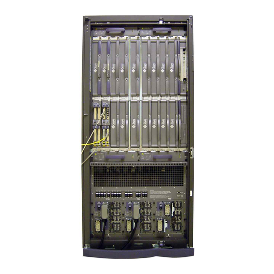
Page 36: Figure 1-1 Sun Fire E25K/E20K Systems Component Numbering-Front
LINK (0, 1), remote power to I/O expansion racks (not used) PS0 (AC0, AC1), power supplies PS1 (AC0, AC1), power supplies PS2 (AC0, AC1), power supplies Sun Fire E25K/E20K Systems Component Numbering—Front FIGURE 1-1 Sun Fire E25K/E20K Systems Service Manual • April 2004... -
Page 37: Figure 1-2 Sun Fire E25K System Component Numbering-Rear
LINK (2, 3), remote power to I/O expansion racks (not used) PS3 (AC0, AC1), power supplies PS4 (AC0, AC1), power supplies PS5 (AC0, AC1), power supplies Sun Fire E25K System Component Numbering—Rear FIGURE 1-2 Chapter 1 Guidelines, Indicators, and Nomenclature... -
Page 38: Figure 1-3 Sun Fire E20K System Component Numbering-Rear
LINK (2, 3), remote power to I/O expansion racks (not used) PS3 (AC0, AC1), power supplies PS4 (AC0, AC1), power supplies PS5 (AC0, AC1), power supplies Sun Fire E20K System Component Numbering—Rear FIGURE 1-3 1-10 Sun Fire E25K/E20K Systems Service Manual • April 2004... -
Page 39: Figure 1-4 Cassette Component Numbering-Sun Fire E25K Front And Rear, And Sun Fire E20K Front
C3V1, hsPCI+ 66 or 33 MHz, yellow C3V0, hsPCI+ 66 or 33 MHz, yellow 3.3V cassettes Cassette Component Numbering—Sun Fire E25K Front and Rear, and Sun FIGURE 1-4 Fire E20K Front Note – The 3.3V cassette positions are interchangeable and the 5.0V cassette positions are interchangeable. -
Page 40: Safety Precautions
An approved ESD mat provides protection from static damage when used with a wrist strap. The mat also cushions and protects parts that are attached to the printed circuit boards. 1-12 Sun Fire E25K/E20K Systems Service Manual • April 2004... -
Page 41: Special Tools And Shipping Kit Items
Special Tools and Shipping Kit Items The following list represents the special tools and items supplied in the shipping kit box at the time of system delivery: Special Tools and Shipping Kit Items Special Tools in Right-Front Door Two (2) preset 18 in.-lbs (2.2 Nm) torque screwdrivers Special Tools in Shipping Kit: Two (2) system control console cables One (1) 11 in. -
Page 42: System Block Diagrams
• 4 CPU / 4 memory banks • 4 PCI adapters • 2 CPU / 0 memory banks • 2 PCI adapters / 3 WCI links System Architecture Block Diagram FIGURE 1-5 1-14 Sun Fire E25K/E20K Systems Service Manual • April 2004... - Page 43 TopCap Fan Tray 48 Volts Fan Tray Fan Tray 48 Volts Power Centerplane SC0 I C (8) SC1 I C (8) Fan Tray Present (4) Power Supply SC0 I C (9) SC1 I C (9) Power Supply Present (3) Interrupt (3) Power Supply 48 Volts SC0_I...
-
Page 44: Figure 1-7 Power Distribution Block Diagram
System Expander 10 System Expander 9 Centerplane Support 1 System Control Board 1 System Control Peripheral 1 Fan Backplane 1.0 Fan Backplane 1.1 Power Distribution Block Diagram FIGURE 1-7 1-16 Sun Fire E25K/E20K Systems Service Manual • April 2004... -
Page 45: Topcap And Extension Replacement Procedures
C H A P T E R TopCap and Extension Replacement Procedures A TopCap assembly and TopCap extension appear on other Sun Fire E25K/E20K systems. The chapter contains the following sections: Section 2.1, “TopCap Replacement” on page 2-2 Section 2.1.1, “Removing the TopCap” on page 2-2 Section 2.1.2, “Installing the TopCap”... -
Page 46: Topcap Replacement
3. Secure the TopCap assembly with four (4) M4x12 panhead screws. TopCap Extension Replacement 2.2.1 Removing the TopCap Extension 1. Remove the two (2) M4x12 panhead screws attaching the TopCap extension to the chassis. 2. Remove the TopCap extension. Sun Fire E25K/E20K Systems Service Manual • April 2004... -
Page 47: Installing The Topcap Extension
2.2.2 Installing the TopCap Extension 1. Install the new TopCap extension. 2. Secure the TopCap extension with two (2) M4x12 panhead screws. Chapter 2 TopCap and Extension Replacement Procedures... - Page 48 Sun Fire E25K/E20K Systems Service Manual • April 2004...
-
Page 49: System Power
C H A P T E R System Power The Sun Fire E25K/E20K systems have two power modules, each holding three hot- swappable power supplies. One module is on the front of the system and the other module is on the rear of the system. This chapter contains the replacement procedures for the power modules and the 4 kW dual AC–DC power supplies. -
Page 50: Power Module Replacement Procedures
Power Module Replacement Procedures 3.1.1 Power Module Replacement The Sun Fire E25K/E20K systems have two power modules, each holding three power supplies. One module is on the front of the system and the other module is on the rear of the system. See FIGURE 3-2 3.1.2... - Page 51 -y -g seconds -i 0 where seconds is the amount of time before shutdown. 4. Open the Sun Fire E25K/E20K system cabinet access doors. Note – All DC circuit breakers are to remain in the on position at all times.
-
Page 52: Removing A Power Module
M4x8 panhead screws (4) Cover cutout for system circuit breakers Air-inlet screen Air-Plenum Cover FIGURE 3-1 Caution – Handle the EMI honeycomb panel carefully to prevent damage to the screen. Sun Fire E25K/E20K Systems Service Manual • April 2004... - Page 53 5. Remove the air plenum cover and its air-inlet EMI honeycomb panel and air filter. Place on a flat sturdy surface. Caution – The seven (7) power cables and the two (2) control cables MUST BE REMOVED from the system chassis on both the front and rear sides of the system prior to removing the power module.
-
Page 54: Installing A Power Module
3. Secure the power module to the system chassis with the four (4) M4x10 panhead module-to-system mounting screws, as shown in FIGURE 3-2 Sun Fire E25K/E20K Systems Service Manual • April 2004... -
Page 55: Powering On After Power Module Installation
AC–DC 2. Power on the AC0 and AC1 circuit breakers for all power supplies in the system. 3. Close the Sun Fire E25K/E20K system cabinet access doors. 4. Once the main SC is booted, start the domain(s) by typing: sc% setkeyswitch -d domain_id where domain_id is the domain letter A-R. - Page 56 4 kW Dual AC DC Power Supply – Replacement Procedures The Sun Fire E25K/E20K systems have three 4 kW AC–DC hot-swappable power dual supplies at the front of the system and three at the rear of the system. See FIGURE 3-3...
-
Page 57: Kw Dual Ac-Dc Power Supply Leds
3.2.1 4 kW Dual AC–DC Power Supply LEDs 4 kW Dual AC–DC power supply components and LEDs are listed in TABLE 3-1 TABLE 3-2 AC–DC Power Supply Components 4 kW Dual TABLE 3-1 Total Number of Power Supplies Total Number of LEDs Per Per System Power Supply 4 kW Dual... -
Page 58: Kw Dual Ac-Dc Power Supply Replacement
4. Check the power status by using the Sun Management Center or by typing the following SMS command: sc% showenvironment -p powers 5. On the SC, check for error messages in /var/opt/SUNWSMS/adm/platform/messages. 3-10 Sun Fire E25K/E20K Systems Service Manual • April 2004... - Page 59 1. Open the Sun Fire E25K/E20K system cabinet access doors. Caution – Before removing the power supply from the system, the green activation LED must be off and the amber or blue removal OK LED must be on.
- Page 60 FIGURE 3-5 The strain relief for the AC0 power cable housing is positioned downward when connected. The strain relief for the AC1 power cable housings is positioned upward when connected. 3-12 Sun Fire E25K/E20K Systems Service Manual • April 2004...
-
Page 61: Figure 3-5 Ac Power Cord Installation
1. Power on the circuit breakers, AC0 (top breaker) and AC1 (bottom breaker), on the front panel of the power supply. 2. Close the Sun Fire E25K/E20K system cabinet access doors. 3.2.2.6 Verifying a 4 kW Dual AC–DC Power Supply 1. - Page 62 3-14 Sun Fire E25K/E20K Systems Service Manual • April 2004...
-
Page 63: Fan Trays
C H A P T E R Fan Trays The Sun Fire E25K/E20K systems have eight hot-swappable fan trays. Each fan tray has two layers of six fans for a total of twelve fans per tray. There are two fan trays at the top and two fan trays at the bottom on both the front and rear of the system. -
Page 64: Fan Tray Leds
Initial System Power On is Detected Component Powered On Component Powered Off Active Service Remove Active Service Remove Active Service Remove Active Service Remove illustrates the fan tray and the LED locations. FIGURE 4-2 Sun Fire E25K/E20K Systems Service Manual • April 2004... -
Page 65: Fan Tray Replacement Procedures
Activation indicator (green) This system contains four fan trays per side and Service indicator (amber) twelve fans per tray. Removal indicator (amber or blue) Fan Tray LEDs FIGURE 4-2 Fan Tray Replacement Procedures 4.2.1 Isolating a Failed Fan Tray 1. Check that the fans are on. 2. -
Page 66: Powering Off A Fan Tray
Excessive weight on the kick plate will bend the door support brackets. 1. Open the Sun Fire E25K/E20K system cabinet access doors. Caution – Before removing the fan tray from the system, the green activation LED must be off and the amber or blue removal OK LED must be on. -
Page 67: Installing A Fan Tray
Note – Failure of the service LED to transition from on to off within 60 seconds after insertion indicates a power-status control fault. 6. Verify the LED status per TABLE 4-2 7. Close the Sun Fire E25K/E20K system cabinet access doors. Chapter 4 Fan Trays... -
Page 68: Verifying A Fan Tray
2. Check the fan tray status by using the Sun Management Center or by typing the following SMS command: sc% showenvironment -p fans FANTRAY POWER SPEED FAN0 FAN1 FAN2 FAN3 FAN4 FAN5 FAN6 ------ ------ ----- ---- ---- ---- ---- ---- ---- ---- HIGH Sun Fire E25K/E20K Systems Service Manual • April 2004... -
Page 69: System Controller Cpu Board For The System Control (Sc) Board
System Controller CPU Board for the System Control (SC) Board The System Control (SC) board (slot 0) for the Sun Fire E25K/E20K systems support the system controller CPU board, Netra™ CP2140 CompactPCI, and its memory board(s). This chapter contains the removal and replacement procedures for the system controller CPU board and its memory board(s). -
Page 70: System Control (Sc) Board System Controller Cpu Board Replacement Procedures
There are four ground points on the system cabinet, two at the front top left and top right, and two at the rear top left and top right. Caution – The Sun Fire E25K/E20K systems do not support the Netra CP2140 CompactPCI as a hot-swappable component. -
Page 71: Removing The System Control (Sc) Board System Controller Cpu Board
Note – Prior to installation, Sun Microsystems technicians need to reference Infodoc 72037 for the required system controller CPU upgrade information. Inspect the new board before inserting it into the Sun Fire E25K/E20K systems. 1. Remove the connector protective cover from the board being installed and inspect the connector for any damage or gaps between the pins. -
Page 72: Figure 5-1 System Controller Cpu Board Memory Board Installation
3. Align the two bottom memory board connectors (P3 and P4) above the memory board connector sockets (J0601 and J0602), located at the center of the system controller CPU board, and press down firmly, ensuring the two connectors are properly seated. Sun Fire E25K/E20K Systems Service Manual • April 2004... -
Page 73: Verifying The Switch Positions On The System Controller Cpu Board
Note – To avoid microfracture damage to the system controller CPU board, do not apply excessive pressure on any of the connectors. 4. For the second memory board, align the two bottom connectors (P3 and P4) on top of the first memory board connector sockets (P1 and P2) and press down firmly, ensuring the two connectors are properly seated in the first memory board. -
Page 74: Installing The System Controller Cpu Board
Section 6.1.2.5, “Verifying a System Control (SC) Board” on page 6-10. Note – Memory failure might occur due to the installation of an incorrect memory board, memory board failure, or improper installation. Sun Fire E25K/E20K Systems Service Manual • April 2004... - Page 75 2. After the installation of the SC board, the system goes through SCPOST and OpenBoot PROM (OBP). Review the messages on the console. If a problem is found with the memory, an error message is displayed. The memory configuration is recognized in groups indicated as Group 0, Group 1, Group 2, and Group 3.
- Page 76 Sun Fire E25K/E20K Systems Service Manual • April 2004...
-
Page 77: System Control (Sc) Board
C H A P T E R System Control (SC) Board The System Control (SC) board for the Sun Fire E25K/E20K systems is a hot- swappable board at SC0 (front) and SC1 (rear). This chapter contains the replacement procedures for the SC board. -
Page 78: System Control (Sc) Board Replacement
Indicator Functions Description Alarm Not used Ready Component ON and board is READY Reset button Global reset to the SC CPU and PCI reset to the SC Abort button Resets the CPU Sun Fire E25K/E20K Systems Service Manual • April 2004... -
Page 79: Figure 6-1 System Control Board Leds (3U To 6U Conversion Board Option)
illustrates the System Control board and the LED locations. FIGURE 6-1 SC CPU board Abort button Reset button Alarm-user (amber or blue) Ready (green) Main SC board Activation indicator (green) Service indicator (amber) Removal indicator (amber or blue) Spare 6U/3U slot* Activation indicator (green) Service indicator (amber) Removal indicator (amber or blue) -
Page 80: System Control Board (Sc) Replacement Procedures
2. As a superuser on the main SC, make a backup copy of the SMS configuration: sc# smsbackup directory This smsbackup file can be used to recover the SMS configuration in the event of another failure during the replacement. Sun Fire E25K/E20K Systems Service Manual • April 2004... - Page 81 3. From the main SC, failover (switch over) to the spare SC by typing: sc% setfailover force 4. Monitor the SMS log at /var/opt/SUNWSMS/adm/platform/messages on the spare SC for messages similar to the following: sc% tail /var/opt/SUNWSMS/adm/platform/messages Jul 25 11:14:20 2001 xc12-sc1 fomd[378]: [8570 351292396349 NOTICE FailoverMgr.cc 1846] Reset the remote SC Jul 25 11:14:20 2001 xc12-sc1 fomd[378]: [8573 351293425787 NOTICE FailoverMgr.cc 1860] Taking over the main role because the remote SC (current...
- Page 82 Note – The poweroff command only supports poweroff of the other SC (poweroff SC0 at SC1 or SC1 at SC0). If the user executes poweroff of SC0 from SC0, the command will fail. Sun Fire E25K/E20K Systems Service Manual • April 2004...
- Page 83 1. Open the Sun Fire E25K/E20K system cabinet access doors. Caution – Before removing a board from the system, the green activation LED must be off and the amber or blue removal OK LED must be on.
-
Page 84: Figure 6-2 System Control Board
6.1.2.4 Installing a System Control (SC) Board Inspect the new board before inserting it into the Sun Fire E25K/E20K systems. 1. Remove the connector protective cover from the board being installed and inspect the connector for any damaged or gaps between the pins. - Page 85 Jun 16 14:30:05 2003 sun15-sc0: esmd[7167]: [0 4824421445907014 NOTICE Boards.cc 1646] SC at IOx inserted where x is the SC assembly 0 or 1. 10. Close the Sun Fire E25K/E20K system cabinet access doors. Chapter 6 System Control (SC) Board...
- Page 86 3. Ensure the SC boots properly and no errors are reported to the SMS console or /var/adm/messages. An example message is displayed below. Oct 10 19:40:12 2001 Print services started. Oct 10 19:40:16 2001 volume management starting. Oct 10 19:40:17 2001 The system is ready. 6-10 Sun Fire E25K/E20K Systems Service Manual • April 2004...
- Page 87 4. Check that the SC CPU board flash PROMs match the level on the disk: sc% flashupdate -f /opt/SUNWSMS/firmware/SCOBPimg.di SC0/FP0 Current SC FPROM Information ============================ SC at SC0, FPROM 0: Name: SSCOBP-dropins, Version: 1.1 Size: 144, Check Sum: 52295 Date Flashed: 09/17/01 Date Created: 09/17/01 SC Flash Image Information ==========================...
- Page 88 The spare could be either Spare or Main, depending on the state of the opposite SC. 6. Re-enable failover on the main SC by typing: sc% setfailover on 7. Verify failover is enabled by typing: sc% showfailover SC Failover Status: ACTIVE 6-12 Sun Fire E25K/E20K Systems Service Manual • April 2004...
-
Page 89: System Control (Sc) Peripheral Board
C H A P T E R System Control (SC) Peripheral Board The System Control (SC) hot-swappable peripheral board (slot 1) for the Sun Fire E25K/E20K systems support the DVD-ROM, hard drive, and digital audio tape (DAT) peripherals. This chapter contains the replacement procedures for the SC peripheral board, and the DVD-ROM, hard drive, and digital audio tape (DAT) peripherals. -
Page 90: System Control Peripheral Board Leds
System Control (SC) Peripheral Board Components TABLE 7-1 Total Number of System Control Total Number of System Control Number of LEDs Per System Peripheral Boards Per System Peripheral Boards Per Side Control Peripheral Board Sun Fire E25K/E20K Systems Service Manual • April 2004... - Page 91 System Control (SC) Peripheral Board Valid LED Status TABLE 7-2 LEDs After Insertion LEDs After Presence or Initial System Power On is Detected Component Powered On Component Powered Off Active Service Remove Active Service Remove Active Service Remove Active Service Remove System Control must be present and powered on before the SC peripheral board can be powered on.
-
Page 92: Table 7-3 System Control Dvd Peripheral Indicator Function Descriptions
Green ON or OFF and amber ON Error Cleaning Mode Green fast flashing and amber OFF Cleaning in progress Firmware Upgrade Mode Green fast flashing and amber fast flashing Firmware is downloading (auto ejection when complete) Sun Fire E25K/E20K Systems Service Manual • April 2004... -
Page 93: System Control Peripheral Board Replacement Procedures
There are four ground points on the system cabinet, two at the front top left and top right, and two at the rear top left and top right. 1. Open the Sun Fire E25K/E20K system cabinet access doors. Chapter 7 System Control (SC) Peripheral Board... - Page 94 SCSI cable Center SCSI access panel to SCSI cable and hard drives Riveted panel at DVD-ROM and tape drive peripherals SC Peripheral Board and Center Access Panel—Exploded FIGURE 7-2 Sun Fire E25K/E20K Systems Service Manual • April 2004...
-
Page 95: Installing A System Control (Sc) Peripheral Board
7.2.4 Installing a System Control (SC) Peripheral Board Inspect the new board before inserting it into the Sun Fire E25K/E20K systems. 1. Remove the connector protective cover from the board being installed and inspect the connector for any damaged or gaps between the pins. -
Page 96: Verifying A System Control (Sc) Peripheral Board
There are four ground points on the system cabinet, two at the front top left and top right, and two at the rear top left and top right. 1. Open the Sun Fire E25K/E20K system cabinet access doors. 2. Power off the SC board. -
Page 97: Figure 7-3 Sc Peripheral Board Dvd Removal And Access Panel-Exploded
4. At the center SCSI access panel, remove the four (4) M3x6 flathead screws and remove the panel. 5. Disconnect the SCSI ribbon cable connector and the DVD PWR connector from the DVD-ROM peripheral. 6. To access the internal DVD component of the SC peripheral board, remove the four (4) M3x6 panhead screws from the forward mounting panel, as shown in FIGURE 7-3 Forward mounting... -
Page 98: Installing The Dvd-Rom Peripheral On The System Control (Sc) Peripheral Board
7. Install the SC peripheral board. Section 7.2.4, “Installing a System Control (SC) Peripheral Board” on page 7-7. 8. Close the Sun Fire E25K/E20K system cabinet access doors. 7.3.3 Powering On a DVD-ROM Peripheral Power on the SC by using the Sun Management Center or from the main SC by... -
Page 99: Hard Drive Peripheral Replacement Procedures
There are four ground points on the system cabinet, two at the front top left and top right, and two at the rear top left and top right. 1. Open the Sun Fire E25K/E20K system cabinet access doors. 2. Power off the SC board. - Page 100 J3 M3x6 panhead screws (4) on rear access panel M3x6 panhead screws (4) (outer edge) on SCSI access panel SC Peripheral Board Hard Drive Removal and Access Panel—Exploded FIGURE 7-4 7-12 Sun Fire E25K/E20K Systems Service Manual • April 2004...
-
Page 101: Installing The Hard Drive Peripheral On The System Control (Sc) Peripheral Board
4. Install the SC peripheral board. Section 7.2.4, “Installing a System Control (SC) Peripheral Board” on page 7-7. 5. Close the Sun Fire E25K/E20K system cabinet access doors. 7.4.3 Powering On a Hard Drive Peripheral Power on the SC by using the Sun Management Center or from the main SC by... -
Page 102: Digital Audio Tape (Dat) Peripheral Replacement Procedures
There are four ground points on the system cabinet, two at the front top left and top right, and two at the rear top left and top right. 1. Open the Sun Fire E25K/E20K system cabinet access doors. 2. Power off the SC Board. -
Page 103: Installing The Dat Peripheral On The System Control (Sc) Peripheral Board
6. Install the center SCSI access panel and secure with the four (4) M3x6 flathead screws. 7. Install the SC peripheral board. Section 7.2.4, “Installing a System Control (SC) Peripheral Board” on page 7-7. 8. Close the Sun Fire E25K/E20K system cabinet access doors. Chapter 7 System Control (SC) Peripheral Board 7-15... -
Page 104: Powering On A Digital Audio Tape (Dat) Peripheral
About to reset other SC. Are you sure you want to continue? (yes/no)? yes 7.5.4 Verifying a Digital Audio Tape (DAT) Peripheral Verify the DAT. Section 7.2.6, “Verifying a System Control (SC) Peripheral Board” on page 7-8. 7-16 Sun Fire E25K/E20K Systems Service Manual • April 2004... -
Page 105: Cpu (Slot 0) Board
C H A P T E R CPU (Slot 0) Board The standard hot-swappable CPU boards or CPU filler panels for the Sun Fire E25K/E20K systems are inserted into slot 0, expander 0 through 8 (front), and slot 0, expander 9 through 17 (rear). This chapter contains the replacement procedures for the standard CPU board, the CPU board DIMMs, and the CPU filler panels. -
Page 106: Cpu (Slot 0) Board Leds
LEDs After Insertion or Initial System Power On Component Powered On Component Powered Off Active Service Remove Active Service Remove Active Service Remove illustrates the CPU board and the LED locations. FIGURE 8-1 Sun Fire E25K/E20K Systems Service Manual • April 2004... -
Page 107: Cpu (Slot 0) Board Replacement Procedures
Activation indicator (green) Service indicator (amber) Removal indicator (amber or blue) CPU Board LEDs FIGURE 8-1 CPU (Slot 0) Board Replacement Procedures 8.2.1 Isolating a Failed CPU (Slot 0) Board 1. Check for any error messages during POST. 2. On the SC, check for any error messages in /var/opt/SUNWSMS/adm/platform/messages and /var/opt/SUNWSMS/adm/domain_id/messages. -
Page 108: Powering Off A Cpu (Slot 0) Board
Sun Management Center or by typing the following SMS command: sc% deleteboard SBx where x is the CPU Board 0-17. Go to Section 8.2.3, “Removing a CPU (Slot 0) Board” on page 8-5. Sun Fire E25K/E20K Systems Service Manual • April 2004... -
Page 109: Removing A Cpu (Slot 0) Board
ESD-protected surface. Never place the weight of a board on its connector as it is easily damaged. 1. Open the Sun Fire E25K/E20K system cabinet access doors. Caution – Before removing a board from the system, the green activation LED must be off and the amber or blue removal OK LED must be on. - Page 110 CPU processor 1 CPU processor 0 CPU processor 3 CPU processor 2 Insert-eject lever Pawl latch (top) Pawl latch (bottom) Insert-eject lever Memory module DIMMs (32 total) CPU Board Components FIGURE 8-2 Sun Fire E25K/E20K Systems Service Manual • April 2004...
-
Page 111: Installing A Cpu (Slot 0) Board
8.2.4 Installing a CPU (Slot 0) Board Inspect the new board before inserting it into the Sun Fire E25K/E20K systems. 1. Remove the connector protective cover from the board being installed and inspect the connector for any damage or gaps between the pins. -
Page 112: Verifying A Cpu (Slot 0) Board
Jun 16 14:30:05 2003 sun15-sc0: esmd[7167]: [0 4824421445907014 NOTICE Boards.cc 1646] CPU at SBxx inserted where xx is the CPU assembly 0-17. 11. Close the Sun Fire E25K/E20K system cabinet access doors. 8.2.5 Verifying a CPU (Slot 0) Board 1. Using dynamic reconfiguration, configure the CPU board into the domain(s) by... -
Page 113: Cpu (Slot 0) Board Dimm Replacement Procedures
There are four ground points on the system cabinet, two at the front top left and top right, and two at the rear top left and top right. 1. Open the Sun Fire E25K/E20K system cabinet access doors. 2. Remove the CPU board requiring a DIMM replacement by following the procedures in: Section 8.2.2, “Powering Off a CPU (Slot 0) Board”... -
Page 114: Figure 8-3 Cpu Board Memory Dimm Locations
DIMM 1 bank 1, 0 DIMM 0 bank 1, 0 DIMM 3 bank 1, 0 DIMM 2 bank 1, 0 DIMM Bank Processor CPU Board Memory DIMM Locations FIGURE 8-3 8-10 Sun Fire E25K/E20K Systems Service Manual • April 2004... -
Page 115: Installing The Cpu Dimms
Orientation key (short side) CPU DIMM Orientation key (long side) CPU DIMM CPU board Eject lever CPU DIMM Removal FIGURE 8-4 8.3.2 Installing the CPU DIMMs Caution – Be sure you are properly grounded before you begin the hardware removal and installation. There are four ground points on the system cabinet, two at the front top left and top right, and two at the rear top left and top right. -
Page 116: Cpu (Slot 0) Filler Panel Replacement Procedures
7. After installation of the new CPU DIMMs, follow the procedures in: Section 8.2.4, “Installing a CPU (Slot 0) Board” on page 8-7 Section 8.2.5, “Verifying a CPU (Slot 0) Board” on page 8-8 8. Close the Sun Fire E25K/E20K system cabinet access doors. CPU (Slot 0) Filler Panel Replacement Procedures 8.4.1... - Page 117 4. Lock the CPU filler panel by sliding the insert-eject levers into position until they are fully nested with the front handle. 5. Close the Sun Fire E25K/E20K system cabinet access doors. Chapter 8 CPU (Slot 0) Board 8-13...
- Page 118 8-14 Sun Fire E25K/E20K Systems Service Manual • April 2004...
-
Page 119: I/O (Slot 1) Assemblies
C H A P T E R I/O (Slot 1) Assemblies The hot-swappable hsPCI+ assembly or I/O filler panels for the Sun Fire E25K/E20K systems are inserted into slot 1, expander 0 through 8 (front), and slot 1, expander 9 through 17 (rear). This chapter contains the replacement procedures for the standard hsPCI+ assembly and the I/O filler panels. -
Page 120: Hspci+ (Slot 1) Assembly
Failure of the service LED to transition from ON to OFF within 60 seconds after insertion indicates a power-status control fault. illustrates the hsPCI+ assembly and the LED locations. FIGURE 9-1 Sun Fire E25K/E20K Systems Service Manual • April 2004... -
Page 121: Hspci+ I/O (Slot 1) Assembly Replacement Procedures
Front view Cassette 3.3V Cassette 5.0V Activation indicator (green) Activation indicator (green) Service indicator (amber) Service indicator (amber) Removal indicator Removal indicator (amber or blue) (amber or blue) Activation indicator (green) Activation indicator (green) Service indicator (amber) Service indicator (amber) Removal indicator (amber or blue) Removal indicator (amber or blue) - Page 122 Sun Management Center or by typing the following SMS command: sc% deleteboard IOx where x is the hsPCI+ assembly 0-17, and go to Section 9.1.2.3, “Removing an hsPCI+ (Slot 1) Assembly” on page 9-5. Sun Fire E25K/E20K Systems Service Manual • April 2004...
- Page 123 ESD-protected surface. Never place the weight of a board on its connector as it is easily damaged. 1. Open the Sun Fire E25K/E20K system cabinet access doors. Caution – Before removing a board from the system, the green activation LED must be off and the amber or blue removal OK LED must be on.
- Page 124 Failure of the service LED to transition from on to off within 60 seconds after insertion indicates a power-status control fault. 5. Verify the LED status per TABLE 9-2 6. Install all I/O cables. Sun Fire E25K/E20K Systems Service Manual • April 2004...
- Page 125 Jun 16 14:30:05 2003 sun15-sc0: esmd[7167]: [0 4824421445907014 NOTICE Boards.cc 1646] HPCI at IOxx inserted where xx is the hsPCI+ assembly 0-17. 8. Close the Sun Fire E25K/E20K system cabinet access doors. 9.1.2.5 Powering On an hsPCI+ (Slot 1) Assembly...
-
Page 126: Pci Cassette Replacement Procedures
LED TABLE 9-2 descriptions. 1. Open the Sun Fire E25K/E20K system cabinet access doors. 2. Ensure that the adapter in the cassette to be removed has terminated all input/output operations. Refer to the man pages for ifconfig or umount for more information. -
Page 127: Figure 9-2 Pci Cassette Removal
DR attachment point identifier for the PCI cassette. Refer to the rcfgadm man page for attachment point identifier details. 5. Verify that the activation LED is green. 6. Close the Sun Fire E25K/E20K system cabinet access doors. Chapter 9 I/O (Slot 1) Assemblies... -
Page 128: Pci Cassette Card Replacement Procedures
9.3.1.1 Removing the PCI Card from the Cassette 1. Open the Sun Fire E25K/E20K system cabinet access doors. 2. Remove the 3.3v or 5.0v PCI card cassette. 3. To access the PCI slot, remove the two (2) M3x5 flathead screws and remove the EMI cap. -
Page 129: I/O (Slot 1) Filler Panel Replacement Procedures
1. Open the Sun Fire E25K/E20K system cabinet access doors. 2. Insert a Phillips No. 1 screwdriver into the pawl latches, turning counterclockwise to release the lever, and lift the carrier insert-eject lever. - Page 130 9-12 Sun Fire E25K/E20K Systems Service Manual • April 2004...
-
Page 131: Board Set Carrier Plates
C H A P T E R Board Set Carrier Plates The board set carrier plates inside the Sun Fire E25K/E20K systems require special handling. There are also three different configuration setups depending on the board sets the carrier plate is assigned to carry. For increased thermal control, a carrier plate with an air dam has been designed for slots 4, 5, 13, and 14. -
Page 132: Inserting A Board Set Carrier Plate
Caution – Extreme caution must be used when inserting the board set into the card cage of the Sun Fire E25K/E20K systems. The top-right leading edge of the board set must be aligned properly in the card guide before insertion into the system to prevent any component parts from being damaged if hit by the edge of the carrier plate which can result in catastrophic failures to the system operation. - Page 133 Ejector bracket alignment tabs Captive ejector screw Alignment Slot 0 boards on top Ejector bracket Slot 1 alignment slots boards on bottom System board carrier plate (various) (SB1 through SB17, System Control front and rear) carrier plate (SC0 and SC1, front and rear) Carrier Plate Location Placement C A U T I O N...
- Page 134 The Sun Fire E25K/E20K systems hold various carrier plate types. The System Control carrier plate is part number 540-3993. The system board carrier plates are different depending upon their location within the system, part number 541-0119, 541-0120, and 541-0121.
-
Page 135: Carrier Plate Configuration Modification And Replacement
10.2 Carrier Plate Configuration Modification and Replacement The Sun Fire E25K/E20K systems have three varieties of system carrier plate configurations to accommodate the connector locations on the Sun Fireplane interconnect. This field-replaceable unit (FRU) contains the reconfigurable parts to be used with the standard carrier plate for the three types of carrier plate slots... -
Page 136: Two-In-One Carrier Plate Fru Modification Contents
2. Remove the expander board from the carrier plate, as required, and set aside. No modifications are required for standard carrier plate configurations. Note – The Sun Fire E25K system has an expander board installed on each carrier plate. The Sun Fire E20K system only has an expander installed on the slot 0 through slot 8 carrier plates. - Page 137 5. Discard any remaining hardware supplied with the FRU package. 10.2.3 Carrier Plate Configuration and Replacement for Slots 0 and 9 This configuration is for the slots on the left sides of the System Controllers. 1. Remove the carrier plate from the system. Note –...
-
Page 138: Carrier Plate Replacement For Standard Configurations Of Slots 4, 5, 13, And
Note – The Sun Fire E25K system has an expander board installed on each carrier plate (with air dam) at slots 4, 5, 13 and 14. The Sun Fire E20K system only has an expander installed on the slot 4 through slot 5 carrier plates. -
Page 139: System Control Expander Board Set
C H A P T E R System Control Expander Board Set The system control expander board set for the Sun Fire E25K/E20K systems consists of a carrier plate that holds the hot-swappable centerplane support board and the hot-swappable System Control (SC) board at SC0 (front) and SC1 (rear). This chapter contains the replacement procedures for the centerplane support board. -
Page 140: Centerplane Support Board Replacement
Failure of the service LED to transition from ON to OFF within 60 seconds after insertion indicates a power-status control fault. illustrates the centerplane support board and the LED locations. FIGURE 11-1 11-2 Sun Fire E25K/E20K Systems Service Manual • April 2004... -
Page 141: Centerplane Support Board Replacement Procedures
Centerplane support board Carrier plate J6 LED connector Activation indicator (green) Service indicator (amber) Centerplane support Removal indicator board (amber or blue) Centerplane Support Board LEDs FIGURE 11-1 11.2 Centerplane Support Board Replacement Procedures Caution – The centerplane support board and mounting system (carrier plate) are also used as the electrical interface and mounding mechanism for the system controller. -
Page 142: Isolating A Failed Centerplane Support Board
Lift the board and place the other hand under the bottom, or back, of the board placing the bottom, or back, on an ESD-protected surface. Note – Never place the weight of a board on its connector as it is easily damaged. 11-4 Sun Fire E25K/E20K Systems Service Manual • April 2004... - Page 143 1. Open the Sun Fire E25K/E20K system cabinet access doors. Caution – Before removing a board from the system, the green activation LED must be off and the amber or blue removal OK LED must be on.
-
Page 144: Installing A Centerplane Support Board
4. Secure the eight (8) M3x8 panhead screws. 5. Firmly secure the centerplane support board to the carrier plate with the two (2) M3 cross-slotted shoulder panhead screws. 11-6 Sun Fire E25K/E20K Systems Service Manual • April 2004... -
Page 145: Powering On A Centerplane Support Board
9. Install the SC peripheral. Section 7.2.4, “Installing a System Control (SC) Peripheral Board” on page 7-7. 10. Close the Sun Fire E25K/E20K system cabinet access doors. 11.2.5 Powering On a Centerplane Support Board 1. Power on the centerplane support board by using the Sun Management Center or... - Page 146 11-8 Sun Fire E25K/E20K Systems Service Manual • April 2004...
-
Page 147: System Expander Board Set
C H A P T E R System Expander Board Set The system expander board set for the Sun Fire E25K/E20K systems consists of a carrier plate that holds the hot-swappable system expander board and optional system boards or I/O filler panels. This board set is inserted at I/O expander 0 through 8 (front) and I/O expander 9 through 17 (rear). -
Page 148: System Expander Board Leds
Any slot 0 or slot 1 board present in the expander being replaced must be deconfigured, powered off, and removed prior to removing or replacing the expander. If the expander is configured as a split slot, up to two domains can be affected. 12-2 Sun Fire E25K/E20K Systems Service Manual • April 2004... -
Page 149: Expander Board Replacement Procedures
System System expander Carrier plate expander board board SRAM DIMM J2 LED connector Activation indicator (green) Service indicator (amber) Removal indicator (amber or blue) System Expander Board LEDs FIGURE 12-1 12.2 Expander Board Replacement Procedures 12.2.1 Isolating a Failed Expander Board 1. -
Page 150: Powering Off An Expander Board
Note – You might need to shut down more than one domain if the expander is part of a split-slot domain. 4. Power off the hardware associated with the domain(s) by typing: SC% setkeyswitch -d domain_id off 12-4 Sun Fire E25K/E20K Systems Service Manual • April 2004... -
Page 151: Removing An Expander Board
The references to those procedures are included in the following steps: 1. Open the Sun Fire E25K/E20K system cabinet access doors. Caution – Before removing a board from the system, the green activation LED must be off and the amber or blue removal OK LED must be on. -
Page 152: Figure 12-2 Expander Board And Carrier Plate-Exploded
(6) J2 LED Connector standoffs (3) and M3x8 panhead screws (3) Carrier plate Expander board CDC SRAM DIMM M3 cross-slotted shoulder panhead screw Expander Board and Carrier Plate—Exploded FIGURE 12-2 12-6 Sun Fire E25K/E20K Systems Service Manual • April 2004... -
Page 153: Installing An Expander Board
13. Place the expander board on an ESD-protected surface, component side up. 14. Review the platform message log to verify SMS has received the message that the component has been removed, by typing: sc% showlogs -F Review the board removal message. You will see a message similar to the one as follows. -
Page 154: Powering On An Expander Board
Jun 16 14:30:05 2003 sun15-sc0: esmd[7167]: [0 4824421445907014 NOTICE Boards.cc 1646] EXB at EXxx inserted where xx is the expander assembly 0-17. 13. Close the Sun Fire E25K/E20K system cabinet access doors. 12.2.5 Powering On an Expander Board Power on the expander by using the Sun Management Center or by typing the... - Page 155 domain_id is the letter A-R of the target domain(s) for the component. If the domain(s) were shut down prior to the expander replacement, start the domain(s) with: sc% setkeyswitch -d domain_id Note – You might need to use setkeyswitch for more than one domain if the expander is part of a split-slot domain.
- Page 156 12-10 Sun Fire E25K/E20K Systems Service Manual • April 2004...
-
Page 157: Sun Fireplane Interconnect Replacement Procedure
Replacement Procedure The Sun Fireplane interconnect is designed with a coherent shared-memory protocol and resides in the center of the Sun Fire E25K/E20K systems. This chapter contains the replacement procedures for the Sun Fireplane interconnect. This chapter contains the following sections: Section 13.1, “Isolating a Failed Sun Fireplane Interconnect”... -
Page 158: Isolating A Failed Sun Fireplane Interconnect
Therefore, all possible precautions should be taken to protect these boards against static damage. Transport board assemblies on an ESD static-protected cart whenever possible. Use a static wrist strap when handling. 13-2 Sun Fire E25K/E20K Systems Service Manual • April 2004... -
Page 159: Table 13-1 Component Serial Numbers Worksheet
6. Open and remove all Sun Fire E25K/E20K system cabinet access doors. 7. Use the Component Serial Numbers Worksheet to note the serial numbers and locations of the existing boards as well as the serial number and revision of the new Sun Fireplane interconnect assembly ( ). -
Page 160: Powering Off The System For Sun Fireplane Interconnect Replacement
On the main SC, power off the spare SC by typing: sc% poweroff SCx where x is 0 or 1, dependent upon which SC is the spare. 13-4 Sun Fire E25K/E20K Systems Service Manual • April 2004... -
Page 161: Removing The Sun Fireplane Interconnect From The Chassis
Interconnect From the Chassis The Sun Fireplane interconnect assembly can only be removed from the front of the Sun Fire E25K/E20K systems. Follow the front and rear notations in this procedure carefully. Caution – The Sun Fireplane interconnect assembly weighs 30.0 lb (13.6 kg). Use proper heavy-lifting procedures when removing this unit. - Page 162 Continue to pull the assembly forward to clear the system chassis. 13-6 Sun Fire E25K/E20K Systems Service Manual • April 2004...
-
Page 163: Figure 13-1 Sun Fireplane Interconnect-Front And Rear View
Front View Insertion guide rails Stiffener Phillips captive screws (22) Insertion guide handles Rear View Insertion guide rails Stiffener Chassis guide pins Power centerplane alignment pins Sun Fireplane Interconnect—Front and Rear View FIGURE 13-1 Caution – The ASICs on the Sun Fireplace interconnect assembly are easily damaged. -
Page 164: Installing The Sun Fireplane Interconnect Into The Chassis
Chassis The Sun Fireplane interconnect assembly can only be removed from the front of the Sun Fire E25K/E20K systems. Follow the front and rear notations in this procedure carefully. Caution – The Sun Fireplane interconnect assembly weighs 30.0 lb (13.6 kg). Use proper heavy-lifting procedures when removing this unit. -
Page 165: Powering On The System After The Sun Fireplane Interconnect Installation
3. Power on the AC0 and AC1 circuit breakers for all power supplies in the system. 4. Close the Sun Fire E25K/E20K system cabinet access doors. 5. Once the main SC is booted and SMS is running, start the domain(s) by typing: sc% setkeyswitch -d domain_id where domain_id is the domain letter A-R. - Page 166 13-10 Sun Fire E25K/E20K Systems Service Manual • April 2004...
-
Page 167: Fan Backplane Replacement Procedure
There are four fan backplanes mounted above the Sun Fireplane interconnect and four below the power centerplane. The fan backplane provides the power distribution to the eight fan trays in the Sun Fire E25K/E20K systems. This chapter contains the replacement procedures for the fan backplanes. -
Page 168: Powering Off For Fan Backplane Removal
As a superuser on the spare SC, shut down the spare SC by typing: sc_spare# shutdown -y -g seconds -i 0 where seconds is the amount of time before shutdown. 14-2 Sun Fire E25K/E20K Systems Service Manual • April 2004... -
Page 169: Removing A Fan Backplane
14.2 Removing a Fan Backplane There are two fan backplanes on the front of the Sun Fire E25K/E20K systems and two on the rear. The front fan backplane locations are shown in FIGURE 14-1 Note – All DC circuit breakers are to remain in the on position at all times. -
Page 170: Figure 14-1 Fan Backplane Locations-Front
5, 6, 7, and 8 front (side 0) or slots 14, 15, 16, and 17 rear (side 1). Remove additional carrier plates, as needed. 5. Disconnect the power cable connector and the control ribbon cable connector from the fan backplane. See FIGURE 14-2 14-4 Sun Fire E25K/E20K Systems Service Manual • April 2004... -
Page 171: Installing A Fan Backplane
Control ribbon cable connector Power cable connector Left fan tray connection Right fan tray connection Fan Backplane Connections FIGURE 14-2 Note – Avoid dropping screws into system cabinet during removal. 6. Remove the ten (10) M4x6 panhead screws by using a Phillips No. 2 extra long (11 in. -
Page 172: Powering On After Fan Backplane Installation
AC–DC 3. Power on the AC0 and AC1 circuit breakers for all power supplies in the system. 4. Close the Sun Fire E25K/E20K system cabinet access doors. 5. Once the main SC is booted, start the domain(s) by typing: sc% setkeyswitch -d domain_id on where domain_id is the domain letter A-R. -
Page 173: Power Centerplane Replacement Procedure
Power is distributed to all board sets through the power centerplane which is located beneath the Sun Fireplane interconnect. The power centerplane can be removed only from the front of the Sun Fire E25K/E20K systems. Access must be obtained by also removing all boards from the rear. Follow the front and rear notations in this procedure carefully. -
Page 174: Powering Off The System For Power Centerplane Replacement
On the main SC, power off the spare SC by typing: sc% poweroff SCx where x is 0 of 1, dependent upon which SC is the spare. 15-2 Sun Fire E25K/E20K Systems Service Manual • April 2004... -
Page 175: Removing The Power Centerplane
-y -g seconds -i 0 where seconds is the amount of time before shutdown. 4. Open the Sun Fire E25K/E20K system cabinet access doors. Note – All DC circuit breakers are to remain in the on position at all times. - Page 176 Power Centerplane Power Control Connections FIGURE 15-1 6. From the cable tie-down panel beneath the power centerplane, disconnect the P1.9 six-wire friction-fit 48V power connector from J1.9 by depressing the end clips. 15-4 Sun Fire E25K/E20K Systems Service Manual • April 2004...
- Page 177 7. Remove the eighteen (18) voltage-and-return DC power cables from the power centerplane by loosening the captive screw of each cable while pulling back on the lug. 8. Remove the seven (7) cross-slotted shoulder standoff nuts from the power centerplane. From the front of the system: 1.
-
Page 178: Installing The Power Centerplane Assembly Into The Chassis
J0.9 on the cable tie-down panel. 4. Connect the five (5) ribbon cable connectors to the power centerplane. 5. Install the DC cable cover and secure with nine (9) M4x8 Phillips screws. 15-6 Sun Fire E25K/E20K Systems Service Manual • April 2004... -
Page 179: Figure 15-2 Voltage-And-Return Reference Designation Labels-Front And Rear
Internal label of power centerplane voltage-and-return connection—front W2-V W2-R W3-V W1-V W3-R W4-V W0.SC-R W4-R W1-R W5-V W0.PH-R W5-R W0.CSB-R W6-V W0.CSB-V W6-R W0-V W7-V W0.SC-V W7-R W8-V W0-R W0.PH-V W8-R Internal label of power centerplane voltage-and-return connections—rear W11-V W11-R W12-V W12-R W13-V... - Page 180 7. Install all system expander and the centerplane support board sets by following the procedures in: Section 12.2.4, “Installing an Expander Board” on page 12-7 Section 11.2.4, “Installing a Centerplane Support Board” on page 11-6 15-8 Sun Fire E25K/E20K Systems Service Manual • April 2004...
-
Page 181: Powering On The System After Power Centerplane Installation
2. Connect all I/O cables referencing the cable label for proper identification. 3. Power on the AC0 and AC1 circuit breakers for all power supplies in the system. 4. Close the Sun Fire E25K/E20K system cabinet access doors. 5. Once the main SC is booted, start the domain(s) by typing: sc% setkeyswitch -d domain_id where domain_id is the domain letter A-R. - Page 182 15-10 Sun Fire E25K/E20K Systems Service Manual • April 2004...
- Page 183 C H A P T E R Cable Replacement Procedures shows the locations of the internal system cable connections for the Sun FIGURE 16-1 Fire E25K/E20K systems. Cable functions are further defined in the diagrams shown FIGURE 16-2 FIGURE 16-3 FIGURE 16-4 FIGURE 16-5 FIGURE 16-6...
-
Page 184: Figure 16-1 Sun Fire E25K/E20K Systems Internal Cable Connections
Top fan tray backplane Power centerplane Bottom fan tray backplane Voltage-and-return wiring diagram Interface connectors Sun Fire E25K/E20K Systems Internal Cable Connections FIGURE 16-1 16-2 Sun Fire E25K/E20K Systems Service Manual • April 2004... -
Page 185: Cable Replacement Procedures
Power centerplane grounding screws Top fan tray backplane Power centerplane Cable tie down panel Bottom fan tray backplane Interface connectors Wiring Locations 48V high-current wires: Red, top Black, bottom 48V low-current wires: Black, left Centerplane support, system control, and Red, right system control peripheral power connector Reference designators on wires (six wire), J0.9 (front), J1.9 (rear) -
Page 186: Figure 16-3 Fan Tray Backplane Fru Cable Diagram-Top Front, Side
C, control 1, J0.1 FT0-3, J0.2 Crossover, J0.3 CSB-SC-SCPER, J0.4 Crossover, J0.5 EXP 2-1-0, J0.6 EXP 5-4-3, J0.7 EXP 8-7-6, J0.8 Power Centerplane Cable Diagram—Bottom Front, Side 0 FIGURE 16-4 16-4 Sun Fire E25K/E20K Systems Service Manual • April 2004... -
Page 187: Figure 16-5 Fan Tray Backplane Fru Cable Diagram-Top Front, Side
FT1-J0 FT1-J1 1 48 VDC-A 2 RTN-A 3 48 VDC-B 4 RTN-B J2 fan power (FT1-P2) J3 fan control (FT1-P3) Fan Tray Backplane FRU Cable Diagram—Top Front, Side 1 FIGURE 16-5 W11-V W11-R W12-V W12-R W10-V W13-V W1.SC-R W13-R W10-R W14-V W1.PH-R W14-R... - Page 188 (3) Connector bulkhead power module Internal wiring Internal wiring Power supply Power supply Side 1 Side 0 DC Power Distribution Cables—Side 0 and Side 1 FIGURE 16-9 16-6 Sun Fire E25K/E20K Systems Service Manual • April 2004...
-
Page 189: Table 16-1 Cable Termination Table
Cable Termination Table TABLE 16-1 From AWG & From AWG & Power CP Interface Color Function Power CP Interface Color Function F R O N T ( S I D E 0 ) R E A R ( S I D E 1 ) W8-R J0.8-8 10 BLK... -
Page 190: Ac Power Cord
1. As a superuser on the domains, systematically shut down all running domains by typing: domain_name# shutdown -y -g seconds -i 0 where seconds is the amount of time before shutdown. 16-8 Sun Fire E25K/E20K Systems Service Manual • April 2004... - Page 191 -y -g seconds -i 0 where seconds is the amount of time before shutdown. 4. Open the Sun Fire E25K/E20K systems cabinet access doors. Note – All DC circuit breakers are to remain in the on position at all times.
-
Page 192: 48 Vdc Power Cable Replacement
J0.1 J1.7 J0.0 J1.8 J0.9 Rear power module Front power module Power shelf I C cables (3) (front and rear) 48 VDC Power Cables FIGURE 16-10 4. Remove the cable(s). 16-10 Sun Fire E25K/E20K Systems Service Manual • April 2004... -
Page 193: Power Shelf I 2 C Or Topcap Cable Replacement
16.2.2.2 Installing the 48 VDC Power Cable 1. Install the new cable. 2. Secure the four (4 per cable) jackscrews holding the 48 VDC cable assemblies to both the top of the power shelf assembly and the cable retaining bracket. 3. -
Page 194: Power Crossover Cable Replacement
5. Reach inside the system, below the fan tray shelf, and release the four (two (2) per connector) male jackscrews (front and rear) holding the 48 VDC power cable assemblies (two (2) per side) to the two (2) power crossover cables. FIGURE 16-10 16-12 Sun Fire E25K/E20K Systems Service Manual • April 2004... -
Page 195: Fan Tray Power Cable Replacement
6. Using a 3/16 inch nut driver, carefully remove the four (4) female jack screws (two (2) per connector) holding the crossover cable connectors to the horizontal connector bracket. 7. Reaching through the lower card guide assembly, remove the cable(s). 16.2.4.2 Installing the Power Crossover Cable 1. -
Page 196: Figure 16-11 Fan Tray Power Cable
8. Remove the thirty-eight (38) (nineteen (19) per side) M4x6 panhead screws retaining the black plastic cable cover attached to the center bulkhead on the front and rear of the system. 16-14 Sun Fire E25K/E20K Systems Service Manual • April 2004... - Page 197 9. Reach through the upper and lower card guide assembly and remove the blue colored connectors attaching the fan power cable to the four (4) fan backplanes. 10. Remove the fan power cable assembly from the system. 16.2.5.2 Installing the Fan Tray Power Cable 1.
-
Page 198: Internal Cable Harness Set Replacement
11. Reach through the upper and lower card guide assembly and remove the grey colored connectors attaching the I C fan cable to the four (4) fan backplanes FIGURE 16-12 16-16 Sun Fire E25K/E20K Systems Service Manual • April 2004... -
Page 199: Figure 16-12 Internal Cable Harness Set
Fan control cable Some cables not shown for clarity Internal Cable Harness Set FIGURE 16-12 12. Disconnect all forty-eight (48) (twenty-four (24) per side) discrete screw lugs and ten (10) (five (5) per side) ribbon cable connectors from the power centerplane at the front and rear of the system. -
Page 200: Topcap Cable Replacement
5. Remove the four (4) M4x12 panhead screws holding the four (4) cable clamps that secure the TopCap cable to the chassis. 16-18 Sun Fire E25K/E20K Systems Service Manual • April 2004... -
Page 201: Figure 16-13 Topcap Cable
6. At the rear of the system, remove the twenty-two (22) M4x30 panhead screws retaining the air plenum cover, and remove both the plenum cover and the honeycomb EMI filter panel. 7. Reach inside the air plenum and release the two (2) male jackscrews holding the internal cable connector to the internal chassis side panel. -
Page 202: Powering On The System
2. Connect all I/O cables referencing the cable label for proper identification. 3. Power on the AC0 and AC1 circuit breakers for all power supplies in the system. 4. Close the Sun Fire E25K/E20K system cabinet access doors. 5. Once the main SC is booted, start the domain(s) by typing: sc% setkeyswitch -d domain_id where domain_id is the domain letter A-R. -
Page 203: Mechanical Components Replacement Procedures
Mechanical Components Replacement Procedures The mechanical components of the Sun Fire E25K/E20K systems consist of the side panels, the front and rear access doors, the six air filters, and the two kick plate assemblies. This chapter contains the replacement procedures for these mechanical components. -
Page 204: Side Panel Replacement
17.1 Side Panel Replacement The Sun Fire E25K/E20K systems have four panels, two per side. 17.1.1 Removing a Side Panel 1. Release the two (2) spring-loaded captive fasteners by pushing inward and making a counterclockwise turn. 2. Using both hands, firmly grasp the panel on each side, near the top, and lift straight up and then outward to remove the panel away from the cabinet. -
Page 205: Removing An Access Door
17.2.1 Removing an Access Door 1. At the top of the door, pull up the spring-loaded pin and remove the peg of the door from the top hinge bracket of the cabinet. 2. Lift the bottom peg out of the bottom hinge bracket and remove the door from the cabinet. -
Page 206: Installing A Kick Plate Assembly
4. Insert the square mounting tube of the kick plate mounting bracket assembly until it is flush with the cabinet. 5. Secure the kick plate with the spring-loaded captive locking pin at the left side of the mounting tube. 17-4 Sun Fire E25K/E20K Systems Service Manual • April 2004... -
Page 207: Periodic Maintenance
C H A P T E R Periodic Maintenance The periodic maintenance of the Sun Fire E25K/E20K systems consists of the air plenum air-intake filter below the lower fan trays and the six air filters located below the power supplies. This chapter contains the procedures for the maintenance of these components. -
Page 208: Cleaning The Air Plenum Panel Air-Intake Screens
Air Plenum Panel Air-Intake Screen for Sun Fire E25K/E20K Systems The air plenum of the air-intake screens of the Sun Fire E25K/E20K systems is located below the bottom fan trays on the front and rear of the system ( FIGURE 18-1... -
Page 209: Cleaning The Air Plenum Air-Intake Screens
18.2 Air Filter Replacement The Sun Fire E25K/E20K systems have three front and three rear air filters, which allow approximately 3500 CFMs per system, that require periodic cleaning or replacing. To prevent restricted air flow and possible equipment failure, perform this procedure when the filters contain trapped particles, or every three months. -
Page 210: Figure 18-2 Filter Replacement-Front And Rear
6. After the six (6) new filters have been replaced, install the faceplates and tighten the captive screws. 7. Close the Sun Fire E25K/E20K system access doors. 8. Place the dirty filters on a flat surface away from air vents that might dislodge the dust particles which can become airborne. -
Page 211: Component Serial Number Worksheet
A P P E N D I X Component Serial Number Worksheet A larger version of the Component Serial Number Worksheet, introduced in Chapter TABLE 13-1 “Component Serial Numbers Worksheet” on page 13-3 this document has been provided in this appendix on page A-3. - Page 212 Sun Fire E25K/E20K Systems Service Manual • April 2004...
- Page 213 Component Serial Number Worksheet Record Date ______________ Slot 1 Slot 0 Board Board Expander Type Type CSB0 EXB0 EXB1 EXB2 EXB3 EXB4 EXB5 EXB6 EXB7 EXB8 CSB1 EXB9 EXB10 EXB11 EXB12 EXB13 EXB14 EXB15 EXB16 EXB17 New Sun Fireplane interconnect S/N: Rev: Appendix A Component Serial Number Worksheet...
- Page 214 Sun Fire E25K/E20K Systems Service Manual • April 2004...
-
Page 215: System Labels
A P P E N D I X System Labels Various labels appear on the Sun Fire E25K/E20K systems to reference a specific component by its assigned component number. There are also caution and instruction labels that are visible inside the access doors as well as internally within the system. -
Page 216: System Chassis And Carrier Plate Labels
Confirm that top and bottom alignment tabs are inserted Align carrier plate with into alignment slots top card guide. Tabs Slots System Chassis and Carrier Plate Label—Carrier Plate Installation Procedures FIGURE B-2 Sun Fire E25K/E20K Systems Service Manual • April 2004... -
Page 217: Fan Tray Labels
The warning label, shown in , is located on each carrier plate. FIGURE B-3 Carrier Plate Warning Label FIGURE B-3 Fan Tray Labels B.3.1 Fan Tray Removal Label The fan tray removal label, shown in , is located at the upper-left outside FIGURE B-4 front corner of each of the four (4) fan trays. -
Page 218: Bottom Fan Tray Component Number Labels
(left-to right) and the System Control board SC0 for slot 0; and the I/O boards IO0 through IO8 (right-to-left) and the system control peripheral board SCPER0 for slot 1. Slot 0, front Slot 1, front SCPER0 Front Component Number Labels FIGURE B-6 Sun Fire E25K/E20K Systems Service Manual • April 2004... -
Page 219: Rear Component Number Labels
B.4.2 Rear Component Number Labels The labels shown in indicate the system CPU boards SB9 through SB17 FIGURE B-7 (left-to right) and the System Control board SC1 for Slot 0; and the I/O boards IO9 through IO17 (right-to-left) and the System Control peripheral board SCPER1 for slot 1. -
Page 220: Centerplane Support Label
13.5 KG (30 LBS.) HEAVY U S E C A U T I O N W H E N L I F T I N G ! Sun Fireplane Interconnect Label FIGURE B-10 Sun Fire E25K/E20K Systems Service Manual • April 2004... -
Page 221: Power Supply Labels
Power Supply Labels B.8.1 Power Supply Component Labels The six power supplies (PS0 through PS5) each have two AC power connections (AC0 and AC1) with labels as shown in FIGURE B-11 Power Supply Component Labels FIGURE B-11 B.8.2 External Power Supply Handle-Instruction Label An external power supply label providing handle rotation and forward pull instructions, as shown in , appears at the upper left corner of each of the... -
Page 222: Power Supply Caution Label
A CAUTION label, indicating APPROACHING END OF UNIT! (due to extensive weight), is located internally at the top end of the power supply unit ( FIGURE B-14 CAUTION APPROACHING END OF UNIT Power Supply CAUTION Label FIGURE B-14 Sun Fire E25K/E20K Systems Service Manual • April 2004... -
Page 223: Sun Fire E25K/E20K Systems Field-Replaceable Units (Fru
A P P E N D I X Sun Fire E25K/E20K Systems Field-Replaceable Units (FRU) The illustrations and tables in this chapter supplement the removal and replacement procedures described in previous chapters. identifies the FRU FIGURE C-1 replacement categories listed in this chapter. -
Page 224: Access Doors And Side Panels
Access Doors and Side Panels lists the Sun Fire E25K/E20K systems front and rear access doors and side TABLE C-1 panels. illustrates each item. FIGURE C-2 Access Doors and Side Panels TABLE C-1 Description Front access door (left) Front access door (right) -
Page 225: Topcap Assembly
TopCap Assembly lists the Sun Fire E25K/E20K systems TopCap assembly parts. TABLE C-2 FIGURE C-3 illustrates each item. TopCap Assembly Components TABLE C-2 Description TopCap TopCap extension TopCap TopCap Extension TopCap Assembly Components FIGURE C-3 Appendix C Sun Fire E25K/E20K Systems Field-Replaceable Units (FRU) -
Page 226: Kick Plate Assembly
Kick Plate Assembly lists the Sun Fire E25K/E20K systems kick plate assembly. TABLE C-3 FIGURE C-4 illustrates this item. Kick Plate Assembly Components TABLE C-3 Description Kick plate Kick plate mounting bracket Kick plate mounting bracket Kick plate Kick Plate Assembly Components FIGURE C-4 Sun Fire E25K/E20K Systems Service Manual •... -
Page 227: System Board Assemblies And Carrier Plates
System Board Assemblies and Carrier Plates lists the Sun Fire E25K/E20K systems board assemblies and filler panels. TABLE C-4 lists the system board assembly carrier plates with part numbers. TABLE C-5 through illustrate each component. FIGURE C-5 FIGURE C-18 System Board Assemblies... -
Page 228: Figure C-5 Centerplane Support Board
Centerplane Support Board FIGURE C-5 System Controller Carrier Plate FIGURE C-6 Sun Fire E25K/E20K Systems Service Manual • April 2004... -
Page 229: Figure C-7 System Expander Carrier Plate (With Air Dam
System Expander Carrier Plate (With Air Dam) FIGURE C-7 System Control Board—3U to 6U Conversion Board Option FIGURE C-8 Appendix C Sun Fire E25K/E20K Systems Field-Replaceable Units (FRU) -
Page 230: Figure C-9 System Control Peripheral Board
System Control Peripheral Board FIGURE C-9 System Expander Board FIGURE C-10 Sun Fire E25K/E20K Systems Service Manual • April 2004... -
Page 231: Figure C-11 System Expander Carrier Plate (With Or Without Air Dam
System Expander Carrier Plate (With or Without Air Dam) FIGURE C-11 CPU Board FIGURE C-12 Appendix C Sun Fire E25K/E20K Systems Field-Replaceable Units (FRU) -
Page 232: Figure C-13 Hot-Swap Pci (Hspci+) I/O Board
Hot-swap PCI (hsPCI+) I/O Board FIGURE C-13 I/O Filler Panel (Used as Required) FIGURE C-14 C-10 Sun Fire E25K/E20K Systems Service Manual • April 2004... -
Page 233: Figure C-15 Cpu Filler Panel (Used As Required
CPU Filler Panel (Used as Required) FIGURE C-15 Front Rear Sun Fireplane Interconnect FIGURE C-16 Appendix C Sun Fire E25K/E20K Systems Field-Replaceable Units (FRU) C-11... -
Page 234: Figure C-17 Power Centerplane
Power Centerplane FIGURE C-17 Fan Backplane FIGURE C-18 C-12 Sun Fire E25K/E20K Systems Service Manual • April 2004... -
Page 235: Fan Tray Cooling Components
Fan Tray Cooling Components lists the Sun Fire E25K/E20K systems fan tray components. TABLE C-6 FIGURE C-19 illustrates each item. Fan Tray Cooling Components TABLE C-6 Description Fan tray Fan backplane Fan trays Fan backplane Fan Tray Cooling Component FIGURE C-19... -
Page 236: Power Supplies And Air Filters
Power Supplies and Air Filters lists the Sun Fire E25K/E20K systems power supply components and air TABLE C-7 filters. , and illustrate each item. FIGURE C-20 FIGURE C-21 FIGURE C-22 Power Supplies and Air Filters TABLE C-7 Description Power supply... -
Page 237: Figure C-21 Power Module
Power module to ZEE bracket (9) Power module to side panel Power Module FIGURE C-21 Air Filter FIGURE C-22 Appendix C Sun Fire E25K/E20K Systems Field-Replaceable Units (FRU) C-15... -
Page 238: System Cables
Control 1 rear cable Power control front cable Power control rear cable TopCap power cable, internal TopCap power cable, external RS-232 cable, internal RS-232 cable, external SC-CPU cable SC-laptop cable C-16 Sun Fire E25K/E20K Systems Service Manual • April 2004... -
Page 239: Figure C-23 Ac Power Cable, Domestic
AC Power Cable, Domestic 2 FIGURE C-24 AC Power Cable, Domestic 2, Wire List TABLE C-10 Wire # Color From Signal P1-X P2-2 Line 1 P1-Y P2-4 Line 2 P1-G P2-3 Earth Appendix C Sun Fire E25K/E20K Systems Field-Replaceable Units (FRU) C-17... -
Page 240: Figure C-25 Ac Power Cable, International
AC Power Cable, International 2 FIGURE C-26 AC Power Cable, International 2, Wire List TABLE C-12 Wire # Color From Signal P1-L P2-2 Line P1-N P2-4 YEL/GRN P1-GND P2-3 Earth C-18 Sun Fire E25K/E20K Systems Service Manual • April 2004... -
Page 241: Figure C-27 Fan Power Cable
14 BLK Fan trays, bottom side 0, return B J1.2-5 FB0_P2-3 14 RED Fan trays, bottom side 0, 48VDC-B J1.2-4 FT1_P2-4 14 BLK Fan trays, top side 1, return B Appendix C Sun Fire E25K/E20K Systems Field-Replaceable Units (FRU) C-19... -
Page 242: Table C-14 Fan Power Cable (Side 1) Termination Table 1
2.9 in. (73.3 mm) P0.FB 6.8 in. (171.8 mm) PIN 1 FB0-P3 PIN 1 5.0 in. (127.3 mm) 16.6 in. (422.9 mm) Fan I C Cable, Front Lower FIGURE C-29 C-20 Sun Fire E25K/E20K Systems Service Manual • April 2004... - Page 243 2.9 in. (73.3 mm) P1-FB 6.8 in. (171.8 mm) PIN 1 FB1-P3 PIN 1 5.0 in. (127.3 mm) 16.6 in. (422.9 mm) Fan I C Cable, Rear Lower FIGURE C-31 Appendix C Sun Fire E25K/E20K Systems Field-Replaceable Units (FRU) C-21...
-
Page 244: Figure C-32 Power Module To Connector Bulkhead, 48 Vdc Power
12.1 in. (309.0 mm) Power Module to Connector Bulkhead, 48 VDC Power FIGURE C-32 Power Module to Connector Bulkhead Cable, 48 VDC Power, Termination TABLE C-15 Table From CONN A To CONN B C-22 Sun Fire E25K/E20K Systems Service Manual • April 2004... -
Page 245: Figure C-33 Connector Bulkhead To Connector Bulkhead, 48 Vdc Crossover
Connector Bulkhead to Connector Bulkhead, 48 VDC Crossover, Termination TABLE C-16 Table From CONN A To CONN B Wire Color 12.1 in. (309.0 mm) Power Module to Connector Bulkhead, I C Signals FIGURE C-34 Appendix C Sun Fire E25K/E20K Systems Field-Replaceable Units (FRU) C-23... - Page 246 3.1 in. (78.3 mm) P1.1.PS 14.0 in. (355.5 mm) PIN 1 13.4 in. (339.1 mm) 20.9 in. (531.6 mm) J1.1 2.2 in. (57.1 mm) CONTROL 1 Control 1 Cable, Front FIGURE C-36 C-24 Sun Fire E25K/E20K Systems Service Manual • April 2004...
- Page 247 3.1 in. (78.3 mm) P0.1.PS 14.0 in. (355.5 mm) PIN 1 13.4 in. (339.1 mm) 20.9 in. (531.6mm) J0.1 2.2 in. (57.1 mm) CONTROL 1 Control 1 Cable, Rear FIGURE C-38 Appendix C Sun Fire E25K/E20K Systems Field-Replaceable Units (FRU) C-25...
- Page 248 Power Control Cable, Front FIGURE C-39 100.0 in. (2540.0 mm) RTUR Power Control Cable, Rear FIGURE C-40 38.3 in. (972.0 mm) PIN 1 P1.FM TopCap Power Cable, Internal FIGURE C-41 C-26 Sun Fire E25K/E20K Systems Service Manual • April 2004...
-
Page 249: Table C-17 Topcap Power Cable, External, Termination Specifications
100.3 in. (2547.0 mm) CONN A CONN B TopCap Power Cable, External FIGURE C-42 TopCap Power Cable, External, Termination Specifications TABLE C-17 From CONN A (DB25P) To CONN B (DB-15P) Appendix C Sun Fire E25K/E20K Systems Field-Replaceable Units (FRU) C-27... -
Page 250: Table C-18 Rs-232 Cable, External, Termination Specifications
86.3 in. (2191.0 mm) CONN A CONN B PATCH PANEL RS-232 Cable, External FIGURE C-44 RS-232 Cable, External, Termination Specifications TABLE C-18 From CONN A (DB9S) To CONN B (DB-15P) C-28 Sun Fire E25K/E20K Systems Service Manual • April 2004... -
Page 251: Table C-19 Sc-Cpu Cable Termination Specifications
600.0 in. (15240.0 mm) CONN A CONN B SC-CPU Cable FIGURE C-45 SC-CPU Cable Termination Specifications TABLE C-19 From CONN A (Mini DIN-8P) To CONN B (DB-25P) 6, jumper to 8 Appendix C Sun Fire E25K/E20K Systems Field-Replaceable Units (FRU) C-29... - Page 252 C-30 Sun Fire E25K/E20K Systems Service Manual • April 2004...
- Page 253 Index front, 1-8 removal, caution, 10-2, 10-4 access door configuration installation, 17-3 memory, 1-3, 8-2 removal, 17-3 rules, 1-2 air filter, C-15 air filter replacement, 18-3 board installation, 8-7 power off, 8-4 removal, 8-5 filler panel board insertion, 10-2 installation, 8-12 removal, 8-12 CPU board, C-9 CPU filler panel, C-11...
- Page 254 11-7 centerplane, 15-6 expander board, 12-8 module, 3-6 fan backplane, 14-6 supply, 48-volt, 3-12 power centerplane, 15-9 side panel, 17-2 power supply 48-volt, 3-13 Sun Fireplane Interconnect, 13-8 Index-2 Sun Fire E25K/E20K Systems Service Manual • April 2004...
- Page 255 system, 13-9 replacement setup, 13-2 power supply, C-14 Sun Fireplane interconnect, C-11 48-volt SunVTS diagnostics, 1-3 installation, 3-12 system power off, 3-11 power on, 13-9 power on, 3-13 testing, 1-3 removal, 3-11 system control board, C-7 caution label, B-8 installation, 6-8 powering on the system, 16-20 power off, 6-4 removal, 6-6...
- Page 256 Index-4 Sun Fire E25K/E20K Systems Service Manual • April 2004...
Need help?
Do you have a question about the Sun Fire E25K and is the answer not in the manual?
Questions and answers