Sun Microsystems Enterprise 6500 Reference Manual
Hide thumbs
Also See for Enterprise 6500:
- Installation manual (76 pages) ,
- Installation manual (2 pages) ,
- Installation manual (12 pages)
Table of Contents
Advertisement
Quick Links
Advertisement
Chapters
Table of Contents
Troubleshooting

Related Manuals for Sun Microsystems Enterprise 6500


Summary of Contents for Sun Microsystems Enterprise 6500
- Page 1 Enterprise ™ ™ 6500/5500/4500 Systems Reference Manual Sun Microsystems Computer Company A Sun Microsystems, Inc. Business 901 San Antonio Road Palo Alto, CA 94303-4900 USA 650 960-1300 Fax 650 969-9131 Part No.: 805-2632-10 RevisionA, April 1998...
- Page 2 Microsystems, Inc. The OPEN LOOK and Sun™ Graphical User Interface was developed by Sun Microsystems, Inc. for its users and licensees. Sun acknowledges the pioneering efforts of Xerox in researching and developing the concept of visual or graphical user interfaces for the computer industry. Sun holds a non-exclusive license from Xerox to the Xerox Graphical User Interface, which license also covers Sun’s licensees who implement OPEN...
-
Page 3: Table Of Contents
Contents Preface xxiii Product Overview 1-1 Standard Features 1-1 Enterprise 6500 and 5500 Systems 1-2 Enterprise 4500 System 1-5 Definitions of Terms 1-6 Internal Options 1-7 Safety Precautions and Tools Requirements 2-1 Safety Precautions 2-1 Symbols 2-2 System Precautions 2-3... - Page 4 SCSI Termination 5-4 Hot-Plug Feature 5-5 Disk Boards 5-6 5.5.1 Removing a Board 5-6 5.5.2 Installing a Board 5-8 5.5.3 Disk Drives 5-12 Clock+ Board 6-1 Handling Boards and Assemblies 6-1 Sun Enterprise 6500/5500/4500 Systems Reference Manual • April 1998...
- Page 5 Device Locations 8-1 Tape and CD-ROM Drives 8-4 8.2.1 Use and Maintenance 8-4 8.2.2 Enterprise 6500/5500 Tape or CD-ROM Drive 8-5 8.2.3 Enterprise 4500 Tape or CD-ROM Drive 8-7 Sun StorEdge FlexiPack Tray 8-10 Disk Drives 8-10 Troubleshooting Overview 9-1...
- Page 6 Defective Disk Drive 10-7 10.7 Defective Power Supplies 10-8 10.8 Defective Clock+ Board 10-9 10.9 Network Does Not Respond 10-10 Powering Off and On 11-1 11.1 Powering Off the System 11-1 Sun Enterprise 6500/5500/4500 Systems Reference Manual • April 1998...
- Page 7 11.1.1 Enterprise 6500/5500 Cabinet Systems 11-1 11.1.2 Enterprise 4500 System 11-3 11.2 Removing the External Cables 11-5 11.3 Restarting the System 11-6 11.4 Reading Boot Messages 11-8 Preparing for Service 12-1 12.1 Servicing Hot-Pluggable Components 12-1 12.2 Powering Off the System 12-1 12.3...
- Page 8 C. SCSI Devices C-1 Media Tray Target IDs C-1 Disk Board Target IDs C-2 C.2.1 Default SCSI ID Numbers C-2 C.2.2 Overriding A Default Disk Board Target ID C-2 SCSI Cable Length C-3 viii Sun Enterprise 6500/5500/4500 Systems Reference Manual • April 1998...
- Page 9 D.8.2 Ethernet D-6 D.8.3 Video Interface D-6 E. Non-Chassis Field Replaceable Units (FRUs) E-1 FRU List E-1 Enterprise 6500/5500 Systems E-2 E.2.1 System Cabinet Fan Tray Assembly E-2 E.2.2 AC Power Cable E-3 E.2.3 Universal System Cabinet Power Sequencer E-5 E.2.4...
- Page 10 SCSI Connector G-11 G.2.8 PCI Connectors G-11 Disk Board G-12 G.3.1 Centerplane Connector G-12 G.3.2 SCSI In Connector G-13 G.3.3 SCSI Out Connector G-13 Clock+ Board G-14 G.4.1 Centerplane Connector G-15 Sun Enterprise 6500/5500/4500 Systems Reference Manual • April 1998...
- Page 11 G.4.2 Serial Port Connectors G-16 G.4.3 Keyboard and Mouse Connector G-17 H. Compliance Statements H-1 Index Index-1 Contents...
- Page 12 Sun Enterprise 6500/5500/4500 Systems Reference Manual • April 1998...
- Page 13 Figures Front Views of the Sun Enterprise 6500/5500 and 4500 Servers 1-2 FIGURE 1-1 Front View of the Enterprise 6500 System Cabinet 1-3 FIGURE 1-2 Rear View of the Enterprise 6500 System Cabinet 1-4 FIGURE 1-3 Bezels for Enterprise 6500/5500 System - Two Examples 1-5...
- Page 14 Removing or Installing a Graphics (UPA) Card 4-24 FIGURE 4-22 SBus+ I/O Board GBIC Connector Locations 4-26 FIGURE 4-23 Graphics+ I/O Board GBIC Connector Locations 4-27 FIGURE 4-24 Removing or Installing a GBIC 4-28 FIGURE 4-25 Sun Enterprise 6500/5500/4500 Systems Reference Manual • April 1998...
- Page 15 JTAG Test Jumper 4-32 FIGURE 4-28 PCI Card Installation/Replacement 4-33 FIGURE 4-29 Filler Panel (Enterprise 5500/4500 Only) 5-3 FIGURE 5-1 Load Board (Enterprise 6500 Systems Only) 5-4 FIGURE 5-2 SCSI Terminator 5-4 FIGURE 5-3 Unlocking and Locking Quarter-Turn Access Slots 5-7 FIGURE 5-4...
- Page 16 Rear Screen and Kick Panel 11-5 FIGURE 11-5 CPU Reset Switch on Clock+ Board 11-7 FIGURE 11-6 System Status LEDs on the Enterprise 6500/5500 Front Panel 11-8 FIGURE 11-7 Status LEDs on the Enterprise 4500 Front Panel 11-9 FIGURE 11-8...
- Page 17 Opening the Power Connector Cover E-4 FIGURE E-2 Replacing the Power Sequencer E-5 FIGURE E-3 Replacing the Fan in the Media Tray in the Enterprise 6500/5500 Systems E-7 FIGURE E-4 Removing the Front Bezel E-8 FIGURE E-5 Removing the Cable Assemblies From the Front of the SCSI Adapter Tray E-9...
- Page 18 CPU/Memory+ Board Connector Locations G-2 FIGURE G-1 CPU/Memory+ Board Centerplane Connector Location G-3 FIGURE G-2 Centerplane Connector Detail G-3 FIGURE G-3 CPU Module 0 Connector (144 Pin) Location G-4 FIGURE G-4 xviii Sun Enterprise 6500/5500/4500 Systems Reference Manual • April 1998...
- Page 19 CPU Module 1 Connector (144 Pin) Location G-4 FIGURE G-5 CPU Module 0 Connector (288 Pin) Location G-4 FIGURE G-6 CPU Module 1 Connector (288 Pin) Location G-4 FIGURE G-7 SBus+ I/O Board Connector Locations G-5 FIGURE G-8 Graphics+ I/O Board Connector Location G-5 FIGURE G-9 PCI+ I/O Board Connector Location G-6 FIGURE G-10...
- Page 20 Sun Enterprise 6500/5500/4500 Systems Reference Manual • April 1998...
- Page 21 LED Status Indicators 11-9 TABLE 11-1 Cover Removal by Assembly 12-2 TABLE 12-1 Enterprise 6500/5500 Physical Specifications A-1 TABLE A-1 Enterprise 6500/5500 Clearance and Service Access A-1 TABLE A-2 Enterprise 6500/5500 Shipping Specifications A-2 TABLE A-3 Enterprise 4500 Physical Specifications A-2 TABLE A-4...
- Page 22 TABLE C-2 Internal SCSI Lengths (Approximate) C-3 TABLE C-3 Example of CPU Placement D-4 TABLE D-1 List of Field Replaceable Units E-1 TABLE E-1 List of Replaceable Components F-2 TABLE F-1 xxii Sun Enterprise 6500/5500/4500 Systems Reference Manual • April 1998...
-
Page 23: Preface
Preface The Sun™ Enterprise™ 6500/5500/4500 Systems Reference Manual is for the qualified service-trained maintenance provider. Using UNIX Commands ® This document may not contain information on basic UNIX commands and procedures such as shutting down the system, booting the system, and configuring devices. - Page 24 To delete a file, type rm filename. value. Shell Prompts Shell Prompts TABLE P-2 Shell Prompt C shell machine_name% C shell superuser machine_name# Bourne shell and Korn shell Bourne shell and Korn shell superuser xxiv Sun Enterprise 6500/5500/4500 Systems Reference Manual • April 1998...
- Page 25 Related Documentation The following documents contain topics that relate to the information in the Sun Enterprise 6500/5500/4500 Systems Reference Manual. Related Documentation TABLE P-3 Application Title Part Number Installation Sun Enterprise 6500/5500/4500 Systems Installation Guide 805-2631 Software SMCC SPARC Hardware Platform Guide 802-5341 Solstice SyMON User’s Guide...
- Page 26 For system compliance class and conformity information, refer to Appendix A, “Regulatory Agency Compliance Statements,” in the system installation guide that came with your Enterprise system. xxvi Sun Enterprise 6500/5500/4500 Systems Reference Manual • April 1998...
-
Page 27: Product Overview
The Sun™ Enterprise™ 6500/5500/4500 systems are available in three styles of enclosures. This manual has specific details for two styles used for the Sun Enterprise 6500, 5500, and 4500 servers ( FIGURE 1-1 Many boards and modules are used in all three enclosures, including the CPU/Memory+ board, various types of I/O+ boards, the Disk board, processor modules, memory modules, most power supplies, and the CD-ROM drive. -
Page 28: Enterprise 6500 And 5500 Systems
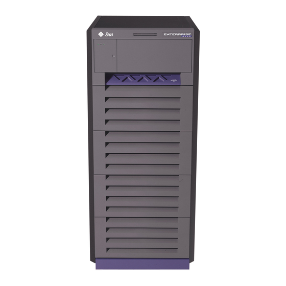
System cabinet (Enterprise 6500 and 5500 systems) Standalone enclosure (Enterprise 4500) Front Views of the Sun Enterprise 6500/5500 and 4500 Servers FIGURE 1-1 Enterprise 6500 and 5500 Systems The minimum configuration for the Enterprise 6500/5500 systems is: Data center system cabinet (system cabinet) -
Page 29: Figure
Enterprise 5500 system. The Enterprise 6500 FIGURE 1-2 system is similar, but has a larger card cage. With panels Without panels Front View of the Enterprise 5500 System Cabinet FIGURE 1-2 shows the rear view of the Enterprise 6500 system. The Enterprise 5500 FIGURE 1-3 system is similar. -
Page 30: Figure 1-3 Rear View Of The Enterprise 6500 System Cabinet
With rear door Without rear door Rear View of the Enterprise 6500 System Cabinet FIGURE 1-3 Sun Enterprise 6500/5500/4500 Systems Reference Manual • April 1998... -
Page 31: Enterprise 4500 System
Enterprise 6500/5500 system. shows two types of panels. FIGURE 1-4 Tape library Blank panel Bezels for Enterprise 6500/5500 System - Two Examples FIGURE 1-4 Enterprise 4500 System The minimum configuration for the Enterprise 4500 system is: 8-slot card cage... -
Page 32: Definitions Of Terms
“rear,” “right,” and “left” are defined in TABLE 1-1 Definitions of Terms TABLE 1-1 Orientation of the Server Front The key switch is located here. Rear The AC power switch and cable are located here. Sun Enterprise 6500/5500/4500 Systems Reference Manual • April 1998... -
Page 33: Internal Options
2 per system 4 per system Can be installed only in slot 14 and slot 15 in the (must use slot Enterprise 6500 system. 15 if only 1 is For easier Disk boards cabling, CPU/Memory+ boards installed) can be installed in the front and Disk boards in the rear of the Enterprise system. -
Page 34: Table 1-2 Internal Options For The Sun Enterprise Server Systems
The expansion cabinet also supports A5000 disk arrays. Refer to documentation that comes A5000 with the disk arrays and the expansion cabinet. StorEdge The Enterprise 6500 and 5500 system cabinets support the StorEdge Flexipack or L400 tape Flexipack or unit. L400 The expansion cabinet also supports the StorEdge Flexipack or L400 tape units. -
Page 35: Safety Precautions And Tools Requirements
Card cage slot System damage Make sure all empty board slots have a filler panel installed. filler panels and and overheating NOTE: You must use load boards instead of filler panels in the 16-slot load boards Enterprise 6500 system card cage. -
Page 36: Symbols
On a system panel, this means the system is running in secure mode and will not respond to commands from the console. The key can be removed. Symbols, Part 1 FIGURE 2-1 Sun Enterprise 6500/5500/4500 Systems Reference Manual • April 1998... -
Page 37: System Precautions
CPU/Memory+ boards, or other printed circuit boards. Use only properly grounded power outlets as described in Section 1.2, “Preparing the Electrical Circuits,” in the Sun Enterprise 6500/5500/4500 Systems Installation Guide, part number 805-2631. Caution – DO NOT make mechanical or electrical modifications to the cabinet. Sun Microsystems™... -
Page 38: Tools Required
Hex driver, 9 mm Wrench, 13 mm (supplied with the system) DIP/IC extraction tool ESD mat Grounding wrist strap Needlenose pliers Hex driver, 3/32 Torque screwdriver (supplied with the system), preset to 6 inch-pounds Sun Enterprise 6500/5500/4500 Systems Reference Manual • April 1998... -
Page 39: Cpu/Memory+ Boards And Components
C H A P T E R CPU/Memory+ Boards and Components To protect both yourself and the equipment, make sure you follow the precautions in Chapter 2 “Safety Precautions and Tools Requirements.” Safety Precautions—page 2-1 Handling Boards and Assemblies—page 3-2 Filler Panels and Load Boards—page 3-3 Hot-Plug Feature—page 3-4 CPU/Memory+ Boards—page 3-5... -
Page 40: Handling Boards And Assemblies
Caution – The heatsinks on the board can be damaged by improper packaging. When storing or shipping the board, ensure that the heatsinks have sufficient protection. Sun Enterprise 6500/5500/4500 Systems Reference Manual • April 1998... -
Page 41: Filler Panels And Load Boards
Empty slots in Enterprise 5500 and 4500 systems must have a filler panel installed FIGURE 3-1 Empty slots in Enterprise 6500 systems must have a load board installed FIGURE 3-2 Load boards and filler panels are inserted into a board slot with the springfingers facing down if inserted in the front of the system;... -
Page 42: Hot-Plug Feature
Caution – If the message: NOTICE: Hot Plug not supported in this system is displayed during boot, do NOT attempt hot-plug in this system or damage to the hardware will occur. Sun Enterprise 6500/5500/4500 Systems Reference Manual • April 1998... -
Page 43: Cpu/Memory+ Boards
The hot-plug feature enables you to insert a new board into a powered-on system, despite the system being “live,” or being supplied with electrical power. When the hot-plug feature is used to add a board to a powered-on system, the system will not use the new board until the system is rebooted. -
Page 44: Figure 3-3 Unlocking And Locking Quarter-Turn Access Slots
Extraction lever CPU/Memory+ Board FIGURE 3-4 4. If a board is not immediately replaced, a load board (Enterprise 6500 systems only) or a filler panel (Enterprise 4500 and 5500 systems only) must be installed in its place. See Section 3.2 “Filler Panels and Load Boards.”... -
Page 45: Installing A Board
2. Pull the ends of both extraction levers outward simultaneously to release the board from the centerplane receptacles ( FIGURE 3-4 3. If a board is not immediately replaced, a load board (Enterprise 6500 systems only) or a filler panel (Enterprise 4500 and 5500 systems only) must be installed in its place. -
Page 46: Figure 3-5 Enterprise 6500 Board Locations
Front view Rear view Slot # Slot # Enterprise 6500 Board Locations FIGURE 3-5 Sun Enterprise 6500/5500/4500 Systems Reference Manual • April 1998... - Page 47 Note – All empty board slots in Enterprise 4500 or 5500 systems must have a filler panel installed to ensure proper cooling and for EMI protection. All empty slots in Enterprise 6500 systems must have load boards installed. Chapter 3...
-
Page 48: Figure 3-7 Board Replacement
The board should insert and seat smoothly. If it binds, remove the board and inspect the card cage slot for any obvious obstructions. Also inspect both the board and the centerplane for bent pins or other damage. 3-10 Sun Enterprise 6500/5500/4500 Systems Reference Manual • April 1998... -
Page 49: Ultrasparc Ii Modules
3. Push the board into the card cage, then simultaneously press both extraction levers to seat the board on the centerplane. Pushing both levers simultaneously avoids twisting the board and bending the connector pins, and mates the board centerplane connector to the matching receptacle on the centerplane. -
Page 50: Handling Precautions
Do not handle the modules by touching the gold pins on the compression connectors. Natural oils on the hands cause these connectors to oxidize and corrode over a period of time, resulting in the need for module cleaning or replacement. 3-12 Sun Enterprise 6500/5500/4500 Systems Reference Manual • April 1998... -
Page 51: Figure 3-9 Ultra Sparc Module Connector Detail
3.4.4.1 Removing a Module Each module is locked to the main board with a single standoff and is connected to the main board by two connectors. The pins within the connectors are compressed to the corresponding board mating surfaces by a metal compression bar which, when secured with screws, compresses the module connector pins to the board mating surfaces ( FIGURE 3-9... -
Page 52: Figure 3-10 Ultrasparc Ii Module Removal And Replacement
Note – Screws on the UltraSPARC II modules must be tightened to 6 inch-pounds. The torque screwdriver that came with your system is set to this specification. 3-14 Sun Enterprise 6500/5500/4500 Systems Reference Manual • April 1998... - Page 53 1. Take the UltraSPARC II module out of the protective packaging and inspect for dust on the connectors. If necessary, clean the connectors with a dry, stiff toothbrush. 2. Remove the applicable CPU/Memory+ board as indicated in Section 3.4.1 “Removing a Board.” 3.
-
Page 54: Memory Modules (Simms)
8 SIMMs each, Bank 0 and Bank 1. Bank 0 and Bank 1 SIMMs occupy alternate slot locations; Bank 0 SIMMs are in the even numbered slots, and Bank 1 SIMMs are in odd numbered slots ( FIGURE 3-12 3-16 Sun Enterprise 6500/5500/4500 Systems Reference Manual • April 1998... - Page 55 Three types of SIMMs ( ) can be used in Bank 0 and Bank 1. TABLE 3-1 SIMM vs. DRAM TABLE 3-1 SIMM DRAM 8 Mbyte 1 Mbyte x4 32 Mbyte 4 Mbyte x4 128 Mbyte 16 Mbyte x4 Bank 0 Bank 1 B0-J3100 B1-J3101...
-
Page 56: Figure 3-13 Ejecting A Simm
All banks must have the same size SIMMs, however, SIMMs from different manufacturers are interchangeable in a single bank if the SIMMs all have the same capacity and speed. Sort the SIMMs into banks of eight using the same size SIMMs. 3-18 Sun Enterprise 6500/5500/4500 Systems Reference Manual • April 1998... - Page 57 Maximizing Performance The following guidelines will result in optimal memory interleaving across boards for performance. These guidelines are for optimal performance and are not requirements for a functional system. The guidelines apply to systems with no SIMMS installed and when adding SIMMs to a system; if you are adding SIMMs, you may need to move some SIMMs to meet the guidelines.
-
Page 58: Figure 3-14 Orienting A Simm
Notch alignment Orienting a SIMM FIGURE 3-14 Installing a SIMM FIGURE 3-15 3-20 Sun Enterprise 6500/5500/4500 Systems Reference Manual • April 1998... -
Page 59: I/O+ Boards And Components
C H A P T E R I/O+ Boards and Components To protect both yourself and the equipment, make sure you follow the precautions in Chapter 2 “Safety Precautions and Tools Requirements.” Handling Boards and Assemblies—page 4-2 Filler Panels and Load Boards—page 4-3 SCSI Termination—page 4-4 Hot-Plug Feature—page 4-5 I/O+ Boards—page 4-6... -
Page 60: Handling Boards And Assemblies
Caution – The heatsinks on the board can be damaged by improper packaging. When storing or shipping the board, ensure that the heatsinks have sufficient protection. Sun Enterprise 6500/5500/4500 Systems Reference Manual • April 1998... -
Page 61: Filler Panels And Load Boards
Empty slots in Enterprise 5500 and 4500 systems must have a filler panel installed FIGURE 4-1 Empty slots in Enterprise 6500 systems must have a load board installed FIGURE 4-2 Load boards and filler panels are inserted into a board slot with the springfingers facing down if inserted in the front of the system;... -
Page 62: Scsi Termination
The I/O+ board in slot 1 controls the internal media tray devices. Therefore, the external SCSI connector on the I/O+ board in slot 1 of a system must be terminated with a SCSI terminator ( FIGURE 4-3 SCSI Terminator FIGURE 4-3 Sun Enterprise 6500/5500/4500 Systems Reference Manual • April 1998... -
Page 63: Hot-Plug Feature
Hot-Plug Feature Enterprise systems have extensive error detection mechanisms, and an Automatic System Reconfiguration (ASR) feature that enables the system to be rebooted with failed components (such as CPUs, memory, or I/O) disabled. When an error is detected, the system can be reconfigured so that the board containing the failed components is placed in low power mode and is no longer accessible. -
Page 64: I/O+ Boards
I/O+ Boards Enterprise 6500/5500/4500 systems support three types of I/O+ boards: SBus+ I/O board with 100 MB/sec Fibre Channel, Graphics+ I/O board with 100 MB/sec Fibre Channel, and PCI+ I/O board. Each board has three LEDs that provide board status... -
Page 65: Figure 4-5 Graphics+ I/O Board With 100 Mb/Sec Fibre Channel
GBIC Graphics+ I/O Board with 100 MB/sec Fibre Channel FIGURE 4-5 PCI+ I/O Board FIGURE 4-6 Chapter 4 I/O+ Boards and Components... -
Page 66: Removing A Board
See Chapter 11 “Powering Off and On” and then Section 4.5.2.2 “Removing a Board from a Powered-Off System.” Sun Enterprise 6500/5500/4500 Systems Reference Manual • April 1998... -
Page 67: Figure 4-7 Unlocking And Locking Quarter-Turn Access Slots
1. Ensure that the board has been disabled by the ASR software. See Section 4.4 “Hot-Plug Feature.” Once disabled by ASR, one of two results occurs: The three LEDs on the board are not lit (board has no power). The outer two green LEDs are not lit and the middle yellow LED is lit (board is in low power mode). -
Page 68: Figure 4-8 Extraction Lever In Extract Position
Extraction Lever in Extract Position FIGURE 4-8 5. If a board is not immediately replaced, a load board (Enterprise 6500 systems only) or a filler panel (Enterprise 4500 and 5500 systems only) must be installed in its place. -
Page 69: Installing A Board
4. If a board is not immediately replaced, a load board (Enterprise 6500 systems only) or a filler panel (Enterprise 4500 and 5500 systems only) must be installed in its place before powering on the system. See Section 4.2 “Filler Panels and Load Boards.”... -
Page 70: Figure 4-9 Enterprise 6500 Board Locations
Front View Rear View Slot # Slot # Enterprise 6500 Board Locations FIGURE 4-9 4-12 Sun Enterprise 6500/5500/4500 Systems Reference Manual • April 1998... -
Page 71: Figure 4-10 Enterprise 5500/4500 Board Locations
PCM can cool the respective boards. Note – All empty board slots in Enterprise 6500 systems must have a load board installed to ensure proper cooling and for EMI protection. All empty board slots in Enterprise 5500 or 4500 systems must have a filler panel installed. -
Page 72: Figure 4-11 Board Replacement
The board should insert and seat smoothly. If it binds, remove the board and inspect the card cage slot for any obvious obstructions. Also inspect both the board and the centerplane for bent pins or other damage. 4-14 Sun Enterprise 6500/5500/4500 Systems Reference Manual • April 1998... - Page 73 3. Push the board into the card cage, then simultaneously press both extraction levers to seat the board on the centerplane. Pushing both levers simultaneously avoids twisting the board and bending the connector pins, and mates the board centerplane connector to the matching receptacle on the centerplane.
-
Page 74: Sbus Cards
There are three SBus card locations on the SBus+ I/O board; the Graphics+ I/O board has two. SBus 1 SBus 2 SBus 0 SBus+ I/O Board SBus Card Connectors FIGURE 4-12 SBus 2 SBus 0 Graphics+ I/O Board SBus Card Connectors FIGURE 4-13 4-16 Sun Enterprise 6500/5500/4500 Systems Reference Manual • April 1998... -
Page 75: Figure 4-14 Locking And Unlocking Standoffs
4.5.4.1 Nylon Standoffs Nylon standoffs lock the SBus and graphics (UPA) cards to the I/O+ boards FIGURE 4-14 To unlock a standoff, pull up the tip insert. To lock a standoff, first ensure that the module or card rests on the standoff flange, then press down the tip insert. -
Page 76: Figure 4-15 Removing Or Installing An Sbus Card
Installing an SBus Card Removing Adapter and Card Retainer Note – If the new SBus card does not have an adapter plate or card retainer, proceed to Section t “Installation” on page 4-22. 4-18 Sun Enterprise 6500/5500/4500 Systems Reference Manual • April 1998... - Page 77 1. Attach a wrist strap and take the SBus card out of the protective packaging and place the SBus card on an antistatic mat. 2. Remove the adapter bracket from the SBus card rear panel ( FIGURE 4-16 Remove the two screws securing the adapter to the card rear panel (the adapter bracket and the screws are not needed for this installation).
- Page 78 SBus card. In the event of “loss of carrier” or “not responding” errors, check the status of the link enable on both the SBus card and the hub. 4-20 Sun Enterprise 6500/5500/4500 Systems Reference Manual • April 1998...
-
Page 79: Figure 4-18 Dsbe/S Sbus Card
Jumper J0302 Springfinger Back panel Jackscrews Phillips screw DSBE/S SBus Card FIGURE 4-18 J0302 FSBE/S SBus Card FIGURE 4-19 Chapter 4 I/O+ Boards and Components 4-21... -
Page 80: Figure 4-20 Disabling And Enabling The Link Integrity Test
9. Press each corner of the SBus card to ensure that it rests on the collar of the standoff. 10. Press down on the tip insert of each standoff to lock the card in place. 4-22 Sun Enterprise 6500/5500/4500 Systems Reference Manual • April 1998... -
Page 81: Graphics (Upa) Cards
11. Replace and tighten the back panel screws to secure the SBus card to the I/O+ board back panel. 12. Replace the I/O+ board using the procedures described in Section 4.5.3 “Installing a Board.” 4.5.5 Graphics (UPA) Cards The Graphics+ I/O board contains a single connector that accommodates graphics (UPA) cards ( FIGURE 4-21 UPA connector... -
Page 82: Figure 4-22 Removing Or Installing A Graphics (Upa) Card
9. Use the procedures in Section 4.5.3 “Installing a Board,” to replace the Graphics+ I/O board. 4-24 Sun Enterprise 6500/5500/4500 Systems Reference Manual • April 1998... - Page 83 4.5.5.2 Installing a Graphics (UPA) Card 1. Use the procedures described in Section 4.5.2 “Removing a Board,” to remove the applicable Graphics+ I/O board. Note – The connector pins on graphics (UPA) cards are extremely delicate, use care when handling. 2.
-
Page 84: Gbics
GBIC (100 MB/sec Fibre Channel). 4.5.6.1 Removing a GBIC 1. Locate the GBIC to be removed ( FIGURE 4-23 FIGURE 4-24 GBIC 0 GBIC 1 SBus+ I/O Board GBIC Connector Locations FIGURE 4-23 4-26 Sun Enterprise 6500/5500/4500 Systems Reference Manual • April 1998... -
Page 85: Figure 4-24 Graphics+ I/O Board Gbic Connector Locations
GBIC 0 GBIC 1 Graphics+ I/O Board GBIC Connector Locations FIGURE 4-24 Chapter 4 I/O+ Boards and Components 4-27... -
Page 86: Figure 4-25 Removing Or Installing A Gbic
3. Insert the GBIC into the I/O+ board panel slot and then push in to firmly seat the card. An audible click indicates the GBIC is properly seated to the onboard connector. 4-28 Sun Enterprise 6500/5500/4500 Systems Reference Manual • April 1998... -
Page 87: Pci Cards
4.5.7 PCI Cards Each PCI+ I/O board can accommodate two PCI (short) cards. The PCI cards are plugged into receptacles on corresponding riser cards that are mounted on the PCI+ I/O board. The riser cards can be one of two voltage types, either 5.0V or 3.3V. The voltage rating of a PCI card must be matched to the rating of the riser card and connector on the motherboard. -
Page 88: Figure 4-26 Pci And Riser Card Removal
5. Once the card is free of the PCI bus connector and the metal catch mechanism, remove the card from the I/O+ board ( FIGURE 4-27 4-30 Sun Enterprise 6500/5500/4500 Systems Reference Manual • April 1998... -
Page 89: Figure 4-27 Pci Card Removal
Catch mechanism PCI Card Removal FIGURE 4-27 Chapter 4 I/O+ Boards and Components 4-31... -
Page 90: Figure 4-28 Jtag Test Jumper
2. Verify that the JTAG Test Jumper is removed/disabled ( FIGURE 4-28 Note – PCI+ I/O boards purchased from Sun Microsystems are shipped with the JTAG Test Jumper disabled or removed on both of the 5.0V riser cards installed on the board. -
Page 91: Figure 4-29 Pci Card Installation/Replacement
Catch mechanism PCI Card Installation/Replacement FIGURE 4-29 4. Once the card is properly positioned as described above and seated properly to the PCI board PCI Bus connector, tighten the locking thumbscrew. Note – Some PCI cards may not require the standoffs provided for mounting. 5. - Page 92 /pci@3,2000/pci@2/SUNW,hme@0,1 (identifies adapter Ethernet interface) /pci@3,2000/pci@2/pci108e,1000@0 /pci@3,2000/pci@2/SUNW,isptwo@4/st /pci@3,2000/pci@2/SUNW,isptwo@4/sd /pci@3,4500/SUNW,isptwo@3 (identifies motherboard SCSI interface) /pci@2,2000/pci@2 /pci@2,2000/pci@2/SUNW,isptwo@4 (identifies adapter SCSI interface) /pci@2,2000/pci@2/SUNW,hme@0,1 (identifies adapter Ethernet interface) /pci@2,2000/pci@2/pci108e,1000@0 /pci@2,2000/pci@2/SUNW,isptwo@4/st /pci@2,2000/pci@2/SUNW,isptwo@4/sd /pci@2,4500/SUNW,hme@1,1 (identifies motherboard Ethernet interface) 4-34 Sun Enterprise 6500/5500/4500 Systems Reference Manual • April 1998...
- Page 93 See Section 4.5.7.2 “Replacing or Installing a PCI Card.” 4.5.7.5 Flash PROM The Sun Enterprise 6500/5500/4500 system I/O+ boards use flash PROMs. Flash PROMs may be reprogrammed and can be updated to the latest firmware code. Refer to the Sun Enterprise 6x00/5x00/4x00/3x00 System Flash PROM Programming Guide for this procedure.
- Page 94 4-36 Sun Enterprise 6500/5500/4500 Systems Reference Manual • April 1998...
-
Page 95: Disk Boards And Components
C H A P T E R Disk Boards and Components To protect both yourself and the equipment, make sure you follow the precautions in Chapter 2 “Safety Precautions and Tools Requirements.” Safety Precautions—page 2-1 Handling Boards and Assemblies—page 5-2 Filler Panels and Load Boards—page 5-3 SCSI Termination—page 5-4 Hot-Plug Feature—page 5-5... -
Page 96: Handling Boards And Assemblies
If a heatsink is loose or broken, obtain a replacement board. Caution – The heatsinks on the board can be damaged by improper packaging. When storing or shipping the board, ensure that the heatsinks have sufficient protection. Sun Enterprise 6500/5500/4500 Systems Reference Manual • April 1998... -
Page 97: Filler Panels And Load Boards
Empty slots in Enterprise 5500 and 4500 systems must have a filler panel installed FIGURE 5-1 Empty slots in Enterprise 6500 systems must have a load board installed FIGURE 5-2 Load boards and filler panels are inserted into a board slot with the springfingers facing down if inserted in the front of the system;... -
Page 98: Scsi Termination
Load Board (Enterprise 6500 Systems Only) FIGURE 5-2 SCSI Termination The last or only Disk board in a system must have the SCSI-out connector terminated with a SCSI terminator ( FIGURE 5-3 SCSI Terminator FIGURE 5-3 Sun Enterprise 6500/5500/4500 Systems Reference Manual • April 1998... -
Page 99: Hot-Plug Feature
Hot-Plug Feature Enterprise systems have extensive error detection mechanisms, and an Automatic System Reconfiguration (ASR) feature that enables the system to be rebooted with failed components (such as CPUs, memory, or I/O) disabled. When an error is detected, the system can be reconfigured so that the board containing the failed components is placed in low power mode and is no longer accessible. -
Page 100: Disk Boards
A maximum of two Disk boards can be installed in Enterprise 6500 systems; four Disk boards can be installed in Enterprise 5500/4500 systems. Note – Disk boards can be installed only in slots 14 and 15 in Enterprise 6500 systems, and slot 15 must be used when installing only one Disk board. -
Page 101: Figure 5-4 Unlocking And Locking Quarter-Turn Access Slots
Disk Board FIGURE 5-5 5. If a board is not immediately replaced, a filler panel or a load board (for Enterprise 6500 systems only) must be installed in its place. See Section 5.2 “Filler Panels and Load Boards.” Chapter 5... -
Page 102: Installing A Board
Enterprise 5500/4500 systems. Use only slot 14 and slot 15 in Enterprise 6500 systems, and you must use slot 15 if only one Disk board is installed. For boards being placed in the rear of the system, ensure that the component side is up. - Page 103 PCM can cool the respective boards. Note – All empty board slots in Enterprise 4500 or 5500 systems must have a filler panel installed to ensure proper cooling. All empty slots in Enterprise 6500 systems must have load boards installed.
-
Page 104: Figure 5-7 Board Replacement
The board should insert and seat smoothly. If it binds, remove the board and inspect the card cage slot for any obvious obstructions. Also inspect both the board and the centerplane for bent pins or other damage. 5-10 Sun Enterprise 6500/5500/4500 Systems Reference Manual • April 1998... - Page 105 3. Push the board into the card cage, then simultaneously press both extraction levers to seat the board on the centerplane. Pushing both levers simultaneously avoids twisting the board and bending the connector pins, and mates the board centerplane connector to the matching receptacle on the centerplane.
-
Page 106: Disk Drives
2. Unlatch and open the ejector drive retainer on the drive to be replaced FIGURE 5-8 Using the extended drive retainer as a handle pull the drive straight out to disengage it from the board mating receptacle and the drive mounting bracket. 5-12 Sun Enterprise 6500/5500/4500 Systems Reference Manual • April 1998... -
Page 107: Figure 5-8 Disk Drive With Ejector Drive Retainer Open
Latch Disk Drive with Ejector Drive Retainer Open FIGURE 5-8 3. If a new drive is to be installed, proceed to the next section. If the drive is not to be replaced, replace the Disk board as described in Section 5.5.2 “Installing a Board”. - Page 108 Note – The last or only disk board in a system must have the SCSI out connector terminated with a fast-wide SCSI terminator, part number 150-2267. 12. Replace the Disk board as described in Section 5.5.2 “Installing a Board.” 5-14 Sun Enterprise 6500/5500/4500 Systems Reference Manual • April 1998...
-
Page 109: Clock+ Board
C H A P T E R Clock+ Board To protect both yourself and the equipment, make sure you follow the precautions in Chapter 2 “Safety Precautions and Tools Requirements.” Safety Precautions—page 2-1 Handling Boards and Assemblies—page 6-1 Clock+ Board—page 6-2 Connectors—page G-14 For your protection, also observe the following safety precautions when setting up your equipment:... -
Page 110: Clock+ Board
Status and control of power supplies The clock+ board consists of the following subsystems: Console Bus Clocks Reset logic JTAG Centerplane connector signals depicts a block diagram of the subsystems and centerplane connector. FIGURE 6-1 Sun Enterprise 6500/5500/4500 Systems Reference Manual • April 1998... - Page 111 led[2..0] LEDs Console Serial ports ConsoleBus Keyboard/ mouse cb_sys_reset Clock_Frequency Centerplane connector ClockBus Clocks Reset ResetBus cb_man_reset button Reset Reset button (xir) JTAGBus JTAG +5VDC +3.3VDC Clock+ Board Block Diagram FIGURE 6-1 Chapter 6 Clock+ Board...
-
Page 112: Consolebus
6.2.3 Reset logic The reset logic consists of four subcircuits for controlling the system reset and error state: Manual reset System reset System error Sun Enterprise 6500/5500/4500 Systems Reference Manual • April 1998... -
Page 113: Removing A Clock+ Board
6.2.4 Removing a Clock+ Board The clock+ board slot ( ) is located near the top of the system, immediately FIGURE 6-2 below the peripheral power supply. The illustration shows an Enterprise 4500 server, but the location is similar for the Enterprise 5500 and 6500 servers. Caution –... -
Page 114: Installing A Clock+ Board
5. Connect any applicable interface cables to the front panel of the board. 6. Turn on system power. See Chapter 11 “Powering Off and On," for this procedure. 7. Boot the system. Sun Enterprise 6500/5500/4500 Systems Reference Manual • April 1998... -
Page 115: Power Supplies
C H A P T E R Power Supplies This chapter describes the power supplies and environmental sensing and reporting in Sun Enterprise systems. Safety Precautions—page 7-2 Power Distribution—page 7-3 Peripheral Power Supply—page 7-3 Troubleshooting a Peripheral Power Supply—page 7-4 Replacing a Peripheral Power Supply—page 7-4 Power/Cooling Module (PCM)—page 7-8 Troubleshooting a PCM—page 7-10... -
Page 116: Safety Precautions
Re-install all cabinet cover panels after performing any and overheating service work on the system. SBus slot covers System damage Install SBus slot covers in all unused SBus slots. and overheating Sun Enterprise 6500/5500/4500 Systems Reference Manual • April 1998... -
Page 117: Power Distribution
Power Distribution The system has a single peripheral power supply, and each pair of board slots has a slot for a PCM. AC is distributed to each of the PCMs within the chassis. The software monitors the status of the AC power source. Current-sharing between power supplies provides redundant power. -
Page 118: Troubleshooting A Peripheral Power Supply
PPS itself. 3. Use a Phillips #1 screwdriver to unlock the quarter-turn access slots ( ) on FIGURE 7-2 the power supply. Locked Unlocked Quarter-Turn Access Slot FIGURE 7-2 Sun Enterprise 6500/5500/4500 Systems Reference Manual • April 1998... -
Page 119: Figure 7-3 Replacing The Enterprise 6500/5500 Pps
4. Pull the ends of the extraction levers outward to release the power supply from the centerplane ( for Enterprise 6500 or 5500 system, FIGURE 7-3 FIGURE 7-4 Enterprise 4500 system). Replacing the Enterprise 6500/5500 PPS FIGURE 7-3 Chapter 7... -
Page 120: Figure 7-4 Replacing The Enterprise 4500 Pps
7. Slide the PPS to the centerplane, then use the extraction levers to seat the PPS. Simultaneously swing both levers inward to the locked position. Do not press on the front panel of the power supply to seat it; doing so will damage the connector pins. Sun Enterprise 6500/5500/4500 Systems Reference Manual • April 1998... - Page 121 Caution – DO NOT FORCE the power supply into a slot; this can damage the power supply and the centerplane. The power supply should insert and seat smoothly. If it binds, remove it, and inspect the slot for any obstructions. Do not damage the springfingers at the bottom of the power supply.
-
Page 122: Power/Cooling Module (Pcm)
That is, an Enterprise 5500 or 4500 system with seven or eight boards and four PCMs is hot-pluggable. (The peripheral power supply acts as the “extra” power supply.) Similarly, an Enterprise 6500 system with fifteen or sixteen boards and eight power supplies is also hot-pluggable. (Seven PCMs are sufficient to power sixteen active boards;... -
Page 123: Cooling Requirements
Note – The presence of an additional (extra) PCM in the system provides redundancy and allows hot-plug of PCMs. Minimum and Redundant Working Power Supplies Required to Power TABLE 7-3 Active Boards Enterprise 5500/4500 Systems Enterprise 6500 System Number Minimum Working Power Redundant Working Power Minimum Working Redundant Working Power... -
Page 124: Troubleshooting A Pcm
Remember the following rules for hot-plug replacement of a PCM: The peripheral power supply must be fully operational (to provide precharge current.) There must be a redundancy of electrical power ( ) in the system. TABLE 7-3 7-10 Sun Enterprise 6500/5500/4500 Systems Reference Manual • April 1998... - Page 125 Rear installation Front installation Position the extraction lever toward the nearest side of the cabinet. PCM — Front and Rear Installation FIGURE 7-6 1. Use the command to determine if precharge current is present. printdiag (1M) 2. Use a Phillips #1 screwdriver to turn each quarter-turn access slot on the power supply to the unlocked position ( FIGURE 7-7 Locked...
- Page 126 7. Use a Phillips #1 screwdriver to turn each quarter-turn access slot to the locked position ( FIGURE 7-7 7-12 Sun Enterprise 6500/5500/4500 Systems Reference Manual • April 1998...
- Page 127 8. Check to be sure the green LED is lit. If the green LED is not lit, the power supply is not seated properly. Repeat Step 5 to Step 8. If the green LED is still not lit, see Chapter 10 “Flow Diagrams for Troubleshooting”...
- Page 128 7-14 Sun Enterprise 6500/5500/4500 Systems Reference Manual • April 1998...
-
Page 129: Internal Scsi And Storage Devices
The Enterprise 4500 cabinet supports internal FC-AL disk drives. The Enterprise 6500 and 5500 cabinets support internal Sun StorEdge A5000 disk arrays. For hole numbers for mounting screws for Sun disk arrays and other storage trays and devices, refer to the Rackmount Placement Matrix, Sun part number 802- 6945. -
Page 130: Figure 8-1 Enterprise 6500 System Storage Device Locations
Front view Tape drive CD-ROM Sun StorEdge FlexiPack Sun StorEdge A5000 disk arrays Front Rear Enterprise 6500 System Storage Device Locations FIGURE 8-1 Sun Enterprise 6500/5500/4500 Systems Reference Manual • April 1998... -
Page 131: Figure 8-2 Enterprise 5500 System Storage Device Locations
Front view Tape drive CD-ROM Sun StorEdge FlexiPack Sun StorEdge A5000 disk arrays Enterprise 5500 System Storage Device Locations FIGURE 8-2 Chapter 8 Internal SCSI and Storage Devices... -
Page 132: Tape And Cd-Rom Drives
The procedures for the use and maintenance of these devices are the same for the different Enterprise systems, whether the devices are mounted horizontally (as in the Enterprise 4500 system) or vertically (as in the Enterprise 5500 and 6500 systems). Sun Enterprise 6500/5500/4500 Systems Reference Manual • April 1998... -
Page 133: Enterprise 6500/5500 Tape Or Cd-Rom Drive
8.2.2 Enterprise 6500/5500 Tape or CD-ROM Drive To remove and replace an existing device, perform steps 1 through 5. To install a tape device for the first time, proceed to step 6. Caution – To prevent breakage, do not grasp the panel by the bottom edge. -
Page 134: Figure 8-5 Cd-Rom/Tape Drive Removal And Replacement
9. On the replacement device set the SCSI ID address to 6 (for a CD-ROM drive) or 5 (for a tape drive). 10. To complete installation of a CD-ROM or tape drive, reverse Step 2 through Step 5. Sun Enterprise 6500/5500/4500 Systems Reference Manual • April 1998... -
Page 135: Enterprise 4500 Tape Or Cd-Rom Drive
8.2.3 Enterprise 4500 Tape or CD-ROM Drive To remove and replace an existing device, perform steps 1 through 5. To install a tape drive for the first time, proceed to step 6. Note – For cooling purposes, the tape drive must be installed on the side nearest the key switch. -
Page 136: Figure 8-7 Removing And Replacing The Media Tray
Note – The tape drive must be installed on the side nearest the key switch for cooling purposes. 6. To install a tape drive for the first time: a. Remove the filler panel by loosening the three captive screws and then removing the panel. Sun Enterprise 6500/5500/4500 Systems Reference Manual • April 1998... - Page 137 b. Separate the filler panel plate from the device mounting bracket by loosening and removing the four screws; discard the filler panel plate. c. Secure the mounting bracket to the new device. d. Set the SCSI address to 5. e. Secure the device and the mounting bracket to the media tray using the three captive screws.
-
Page 138: Sun Storedge Flexipack Tray
Disk Drives The Enterprise systems support Sun StorEdge A5000 disk arrays. For use and maintenance of these devices, refer to the documentation that came with the unit. 8-10 Sun Enterprise 6500/5500/4500 Systems Reference Manual • April 1998... -
Page 139: Troubleshooting Overview
2. Connect the terminal to serial port A on the clock+ board. The clock+ board is located at the back of system, near the top of the card cage. shows the Enterprise 6500/5500 cabinet server. In the 8-slot Enterprise FIGURE 9-1... - Page 140 Even parity Full duplex 5. Turn the key switch to the diagnostic position ( The system will turn on. The diagnostic position puts POST in interactive mode and enables extensive POST tests. Sun Enterprise 6500/5500/4500 Systems Reference Manual • April 1998...
-
Page 141: Hardware Indicator Leds
Hardware Indicator LEDs LEDs indicate system status. The front panel and the boards have three LEDs ). Power supply modules have two LEDs. FIGURE 9-2 Cycling or running Hardware normally Power failure System (3 LEDs): Board (3 LEDs): PCM (2 LEDs): LED Symbols FIGURE 9-2 The LEDs on the system front panel or the clock+ board indicate the status of the... -
Page 142: System Front Panel Leds
LEDs in the system are controlled by OpenBoot™ PROM programming (OBP). 9.2.2 Clock+ Board LEDs The clock+ board also displays system status. The LED codes are the same as for the front panel ( TABLE 9-1 Sun Enterprise 6500/5500/4500 Systems Reference Manual • April 1998... -
Page 143: Cpu/Memory+ And I/O+ Board Leds
9.2.3 CPU/Memory+ and I/O+ Board LEDs summarizes LED codes for boards. The Power, Service, and Cycling TABLE 9-2 symbols are marked on the card cage frame above the respective LEDs. Note that many but not all of the LED codes are the same as the system codes ( TABLE 9-1 Board Status LED Codes TABLE 9-2... -
Page 144: Basic Troubleshooting For Boards
CD-ROM drive. In addition, the +5 VDC output of the peripheral power supply is available at the center plane for current sharing with the +5 VDC outputs of the power supply modules. Sun Enterprise 6500/5500/4500 Systems Reference Manual • April 1998... -
Page 145: Disk Tray Indicators
9.2.6.2 Power/Cooling Modules (PCMs) For a PCM at the front of the card cage, the green LED is to the left of the yellow LED. At the back of the card cage, the LED positions are reversed and the green LED is to the right of the yellow LED. -
Page 146: Diagnosing Problems
You can use the prtdiag command to display: System configuration, including information about clock frequencies, CPUs, memory, and I/O card types. Diagnostic information Failed field replaceable units (FRUs) Refer to the prtdiag man page for instructions. Sun Enterprise 6500/5500/4500 Systems Reference Manual • April 1998... -
Page 147: Post And Openboot
9.3.3.1 History Log Option To isolate an intermittent failure, it may be helpful to maintain a prtdiag history log. Use the prtdiag command with the -l (log) option to send output to a log file in the /var/adm directory. 9.3.3.2 Running prtdiag To run prtdiag, type: % /usr/platform/sun4u/sbin/prtdiag... -
Page 148: Solstice Symon
(GUI) to continuously display system status. Solstice SyMON is intended to complement system management tools such as SunVTS. Solstice SyMON is accessible through an SNMP interface from network tools such as Solstice™ SunNet Manager™. 9-10 Sun Enterprise 6500/5500/4500 Systems Reference Manual • April 1998... -
Page 149: Specific Problems And Solutions
Refer to the Solstice SyMON User’s Guide, part number 802-5355, for starting and operating instructions. Specific Problems and Solutions 9.4.1 Failure of Network Communications Description of the Problem The system cannot communicate with a network if the system and the network hub are not set in the same way for the Ethernet Link Integrity Test. - Page 150 (Repeat for any additional device names.) # eeprom “use-nvramrc?”=true 3. Reboot the system (when convenient) to make the changes effective. Solution 2 Use this alternate method when the system is already in OpenBoot: 9-12 Sun Enterprise 6500/5500/4500 Systems Reference Manual • April 1998...
-
Page 151: Resetting And Power Cycling The System From A Remote Console
1. At the monitor OpenBoot prompt, type: ok nvedit 0: probe-all install-console banner 1: apply disable-link-pulse device-name (Repeat this step for other device names as needed.) (Press CONTROL-C to exit nvedit.) ok nvstore ok setenv use-nvramrc? true 2. Reboot to make the changes effective. 9.4.2 Resetting and Power Cycling the System from a Remote Console... - Page 152 The remote system reset command is useful for resetting the system under general conditions. The remote XIR reset command is used for software development and debugging. 9-14 Sun Enterprise 6500/5500/4500 Systems Reference Manual • April 1998...
-
Page 153: Flow Diagrams For Troubleshooting
C H A P T E R Flow Diagrams for Troubleshooting This chapter lists solutions to these problems: No AC or DC Power—page 10-2 System Cannot Boot—page 10-3 Defective CPU/Memory+ Board—page 10-4 Defective I/O+ Interface Board—page 10-5 Defective Disk Board—page 10-6 Defective Disk Drive—page 10-7 Defective Power Supplies—page 10-8 Defective Clock+ Board—page 10-9... -
Page 154: No Ac Or Dc Power
System error messages Check LEDs on: See Chapter 9. Front panel Clock+ board Peripheral power supply PCMs CPU/Memory+ boards I/O+ boards Diagnosing AC/DC Power Problems FIGURE 10-1 10-2 Sun Enterprise 6500/5500/4500 Systems Reference Manual • April 1998... -
Page 155: System Cannot Boot
10.2 System Cannot Boot Begin INDICATION TEST/PROCEDURE REFERENCE System cannot boot or cannot load UNIX Check LEDs on front panel TABLE 9-1 or clock+ board. Are CPU/Memory+ board LEDs TABLE 9-2 cycling? Is boot disk running? Is OpenBoot set to boot automatically? In OpenBoot, examine system status:... -
Page 156: Defective Cpu/Memory+ Board
Refer to SunVTS User’s Guide. Run SunVTS to test suspected boards, CPUs, SIMMs, power supplies, other FIGURE 10-7 devices. Check related modular power supply. Diagnosing CPU/Memory+ Board Problems FIGURE 10-3 10-4 Sun Enterprise 6500/5500/4500 Systems Reference Manual • April 1998... -
Page 157: Defective I/O+ Interface Board
10.4 Defective I/O+ Interface Board Interface boards are hot-pluggable in many instances. Begin INDICATION TEST/PROCEDURE REFERENCE System error message or LED code identifies a specific board Locate indicated board. Check LEDs on board to verify ASR LED code must be Off-On- has deactivated the board. -
Page 158: Defective Disk Board
Check /var/adm/messages Locate defective SCSI device with probe-scsi-all (OpenBoot command). Check ID jumpers on board. See Section C.2 “Disk Board Target IDs.” Diagnosing Disk Board Problems FIGURE 10-5 10-6 Sun Enterprise 6500/5500/4500 Systems Reference Manual • April 1998... -
Page 159: Defective Disk Drive
10.6 Defective Disk Drive Begin INDICATION TEST/PROCEDURE REFERENCE System error message or device code identifies a specific fault Check system messages to locate failed drive. Halt access to device and power Internal drives: Chapter 7. down the device or tray. Tray: tray service Set ID code (if used) on manual. -
Page 160: Defective Power Supplies
PCM: System error message Board fails Verify PCM is ready: Green LED off. See Section 7.4.4 Yellow LED may be on. “Replacing a PCM.” Diagnosing Power Supply Problems FIGURE 10-7 10-8 Sun Enterprise 6500/5500/4500 Systems Reference Manual • April 1998... -
Page 161: Defective Clock+ Board
10.8 Defective Clock+ Board There is one clock+ board in the system. Caution – The clock+ board is not hot-pluggable. You must halt the operating system and turn off AC power before replacing the clock+ board. Begin INDICATION TEST/PROCEDURE REFERENCE System will not boot Examine LED displays. -
Page 162: Network Does Not Respond
Network Communications” Are the TPE and MII ports in use at See Section 9.4.1 “Failure the same time on the same of Network board? Communications” Diagnosing Network Problems FIGURE 10-9 10-10 Sun Enterprise 6500/5500/4500 Systems Reference Manual • April 1998... -
Page 163: Powering Off And On
See Section 9.4.2 “Resetting and Power Cycling the System from a Remote Console” on page 9-13. 11.1.1 Enterprise 6500/5500 Cabinet Systems 1. Notify users that the system is going down. 2. Back up the system files and data to tape, if necessary. - Page 164 Key Switch (Enterprise 6500 and 5500) FIGURE 11-1 7. Turn the main power switch ( ) to Off. FIGURE 11-2 Caution – Before attempting to service the system cabinet, turn off the AC power. 11-2 Sun Enterprise 6500/5500/4500 Systems Reference Manual • April 1998...
-
Page 165: Figure 1-5 Enterprise 4500 System
Rear view Local/remote switch Main power switch AC Power Switch (Enterprise 6500 and 5500) FIGURE 11-2 11.1.2 Enterprise 4500 System 1. Notify users that the system is going down. 2. Back up the system files and data to tape, if necessary. - Page 166 Key switch (Enterprise 4500) FIGURE 11-3 6. Turn the AC power switch on the system rear off ( FIGURE 11-4 Rear view AC connector Power switch AC Power Switch (Enterprise 4500) FIGURE 11-4 11-4 Sun Enterprise 6500/5500/4500 Systems Reference Manual • April 1998...
- Page 167 11.2 Removing the External Cables 1. Position the server for easy access to the rear. 2. For Enterprise 6500 and 5500 systems only: a. Open the door or pull out the hinge pins ( ) and lift the door off.
- Page 168 2. Enterprise 6500/5500 systems only: turn the Local/Remote switch down, to Local FIGURE 11-2 3. Turn on the AC main power switch (...
- Page 169 6. Watch the terminal screen for POST error messages. At the conclusion of testing, POST automatically configures the system, omitting any devices that have failed diagnostics. After POST ends, the system will boot using the new configuration. Note – If the middle front panel LED (yellow) remains lit after the system has booted, the system has failed POST.
- Page 170 If there is no terminal on this system, check the system status by inspecting LEDs on the front panel. ( FIGURE 11-7 FIGURE 11-8 Front view DC power Fault System running System Status LEDs on the Enterprise 6500/5500 Front Panel FIGURE 11-7 11-8 Sun Enterprise 6500/5500/4500 Systems Reference Manual • April 1998...
-
Page 171: Table 11-1 Led Status Indicators
DC power Fault System running Front view Status LEDs on the Enterprise 4500 Front Panel FIGURE 11-8 summarizes the front panel LED status conditions during and after POST. TABLE 11-1 LED Status Indicators TABLE 11-1 Location Condition Front panel Left or Top On —... - Page 172 11-10 Sun Enterprise 6500/5500/4500 Systems Reference Manual • April 1998...
- Page 173 This chapter contains information about preparing the system for service after the system has been powered off. Servicing Hot-Pluggable Components—page 12-1 Powering Off the System—page 11-1 Internal Access–Enterprise 6500/5500 Systems—page 12-2 Internal Access - Enterprise 4500 System—page 12-10 Powering On the System—page 11-6 12.1...
- Page 174 SCSI Compartment Tape Tray or Tape Library Fan Tray Control Board Centerplane AC power sequencer External Cables CPU/Memory+ Board (Front load) I/O+ or Disk Boards (Rear load) Differential media trays 12-2 Sun Enterprise 6500/5500/4500 Systems Reference Manual • April 1998...
- Page 175 12.3.2 CD-ROM/Tape Device Door The small door to the left of the top panel can contain a CD-ROM drive and/or a tape drive. To open the door: Push on the top right corner of the door. The clasp will release and the door will spring open.
- Page 176 1. Place the bezel against the chassis with ball studs aligned with the catches on the bezel, and tap or press both sides of the bezel into place. 2. Insert the key into the key switch. 12-4 Sun Enterprise 6500/5500/4500 Systems Reference Manual • April 1998...
- Page 177 12.3.4 Front Door Opening the Front Door FIGURE 12-2 12.3.4.1 Opening the Front Door The door is hinged on the left side. The door swings open if pulled firmly on the right side of the top panel. 12.3.4.2 Removing the Front Door 1.
- Page 178 Interface cables should be placed behind the kick panel. To remove the kick panel, loosen the two captive screws. To replace the rear hinged door and kick panel, reverse these instructions. Hinge pin Kick panel Removing the Rear Door FIGURE 12-3 12-6 Sun Enterprise 6500/5500/4500 Systems Reference Manual • April 1998...
- Page 179 12.3.6 Side Panels To remove the side panels: 1. Loosen two slotted-head captive screws near the panel base. 2. Tilt the panel bottom out. 3. Lift the panel up until free of the tabs at the top of the chassis. Panel notches Chassis tabs Side panel...
- Page 180 To keep the cables out of the way, feed them down through the opening below the fan tray area. 3. Pull the fan tray back, tilting the top out so that it clears the chassis. To replace the fan tray, reverse these instructions. 12-8 Sun Enterprise 6500/5500/4500 Systems Reference Manual • April 1998...
- Page 181 12.3.8 Stabilizer Bar The cabinet has six levelling pads. Four pads on the cabinet frame are lowered to touch the floor and prevent the cabinet from rocking. Two levelling pads are part of the stabilizer bar and should not touch the floor. 1.
- Page 182 FIGURE 12-7 Removing the Top Bezel/Panel FIGURE 12-7 3. Tilt the top bezel upward to a 45 angle and remove the bezel. To replace the top bezel, reverse these instructions. 12-10 Sun Enterprise 6500/5500/4500 Systems Reference Manual • April 1998...
- Page 183 12.4.2 Media Tray To remove the media tray: 1. Remove the top bezel. 2. Loosen the three captive screws that hold the tray in place. Insert a screwdriver in the notch at the top center of the media tray to pull out the media tray.
- Page 184 12-12 Sun Enterprise 6500/5500/4500 Systems Reference Manual • April 1998...
- Page 185 77 cm Depth 39 in 99 cm Weight 835 lb, approx 375 kg, approx Power cord 15 ft 4.6 m Enterprise 6500/5500 Clearance and Service Access TABLE A-2 U.S. Metric Front 4 ft 122 cm Rear 3 ft 92 cm...
-
Page 186: Table A-3 Enterprise 6500/5500 Shipping Specifications
Enterprise 4500 Shipping Specifications TABLE A-6 U.S. Metric Height 19.0 in 48 cm Width 23.8 in 60 cm Depth 26.8 in 68 cm Weight 160 lb, approx 72 kg, approx Sun Enterprise 6500/5500/4500 Systems Reference Manual • April 1998... - Page 187 Electrical Specifications Enterprise 6500/5500 Electrical Specifications TABLE A-7 Parameter Value 200-240 Vac Input current Voltage range Current, maximum Current frequency range 47-63 Hz Input power rating Total continuous power 3500W (with 3 drive trays) Volt-Ampere rating 3700 VA BTU rating...
-
Page 188: Table A-9 Enterprise 6500/5500 Temperature, Humidity, And Altitude Limits
20% to 80% RH noncondensing, 93% RH 27C max wb Altitude 9,843 ft (3 km) 39,370 ft (12 km) ° ° *Maximum operating temperature is 95 F (35 C) when using tape media. Sun Enterprise 6500/5500/4500 Systems Reference Manual • April 1998... - Page 189 A P P E N D I X Functional Description System Overview The Enterprise 6500, 5500, and 4500 servers all use variations of the same general card cage design. All systems feature shared-memory multiprocessors and use the same boards, power/cooling modules (PCMs), and operating software.
- Page 190 B-6.” Slot functions All card cage slots are equivalent in the Enterprise 6500, 5500, and 4500 systems. However, it is suggested that you install I/O+ boards at the back of the cage to simplify the installation of interface cables. Install CPU/Memory+ boards at the front of the cage to leave the rear slots for I/O+ boards.
- Page 191 CPU/Memory+ I/O+ board board Memory SBus 1 SYSIO 1 CPU 1 SBus 0 SYSIO 0 CPU 0 Address 8x Data Address 8x Data controller controller controller controller Address bus Data bus Enterprise System Logical Organization FIGURE B-1 There are few differences between board slots and each slot can accept any board type.
-
Page 192: Figure B-2 Sun Enterprise System Cabinet
System Packaging This section describes the features of the system enclosures. B.2.1 Enterprise 6500 Server The Enterprise 6500 server features a 16-slot card cage in a 68-inch data center system cabinet ( FIGURE B-2 Keyswitch Peripheral power supply CD-ROM drive... -
Page 193: Figure B-3 Enterprise 5500 Server
EMI protection. Other types of empty slots must be blocked by filler panels. B.2.2 Enterprise 5500 Server The Enterprise 5500 server is similar to the Enterprise 6500 system but features a shorter, 8-slot, card cage. See on page B-4. -
Page 194: Figure B-4 Enterprise 4500 Standalone Server
All boards are interchangeable between the two versions. All empty slots must be blocked by filler panels for proper airflow, cooling, and EMI protection. Note – The load board that is required for the 16-slot Enterprise 6500 server is not required for the Enterprise 5500. B.2.3... - Page 195 Software The Enterprise software includes two diagnostic packages, Solstice SyMON and SunVTS. Refer to the online manuals for operating instructions. Board Hot-Plug Procedures The CPU/Memory+ board and the I/O+ board are hot-pluggable under certain conditions. If the operating system detects a hardware failure in the board, the system powers down the corresponding board slot and turns off the left green status LED on the board.
-
Page 196: Figure B-5 Cpu/Memory+ Board
All empty slots must have a filler panel or load board installed. Note – The 16-slot Enterprise 6500 card cage requires load boards to reduce the potential for RFI generation. The 8-slot Enterprise 5500 and 4500 card cages use filler panels, which do not have load circuits. - Page 197 B.5.1 CPU Modules Each CPU/Memory+ board has two sets of CPU connectors, marked PROC 0 and PROC 1. The order in which you fill CPU slots is not critical. However, to optimize heat dissipation in the system: Fill all PROC 0 locations on all CPU/Memory+ boards before filling any PROC 1 locations.
-
Page 198: Figure B-6 Simm Slot Locations
The JEDEC standard 3.3 volt SIMMs are available in 8, 32, or 128 Mbyte capacities. All are 168-pin SIMMs. Do not mix different capacities in a bank. Caution – The Enterprise systems SIMMs operate at 3.3V — do not substitute other voltage ratings. B-10 Sun Enterprise 6500/5500/4500 Systems Reference Manual • April 1998... - Page 199 If the rear slots are filled, you can use slots at the front of the cabinet. When located in a front slot, the board is oriented so that the component side is down. Note – All empty card cage slots must contain a load board (Enterprise 6500 server) or filler panel (Enterprise 5500 or 4500 servers).
- Page 200 Note – SBus connector slots 1 and 2 on the SBus+ I/O board can accommodate a double-wide SBus card. SBus connector 1 SBus connector 2 GBIC 0 GBIC 1 Fast/Wide SCSI Twisted-pair Ethernet SBus connector 0 MII external transceiver SBus+ I/O Board FIGURE B-7 B-12 Sun Enterprise 6500/5500/4500 Systems Reference Manual • April 1998...
- Page 201 B.6.2 Graphics+ I/O Board The Graphics+ I/O board with 100 MB/sec Fibre Channel ( ) includes one FIGURE B-8 SYSIO ASIC that provides a single SBus for two plug-in SBus cards, two GBIC (100 MB/sec Fibre Channel) interfaces, and the onboard devices (10/100 Mbit TPE and Single-ended Fast/Wide SCSI).
-
Page 202: Figure 4-6 Pci+ I/O Board
Interface, and Clock Generation. Four of these subsystems: the I/O (PCI Bus), Memory, Bus Interface and internal board interface subsystems include ASICs. The Clock subsystem distributes and generate clocks for the ASICs and PCI Bus Interfaces on the board B-14 Sun Enterprise 6500/5500/4500 Systems Reference Manual • April 1998... - Page 203 Disk Board The Disk board (with two SCSI disks) is an available option for the Enterprise systems. The Enterprise 6500 system supports two Disk boards (only in slots 14 and 15); the Enterprise 5500 and 4500 systems support four Disk boards.
-
Page 204: Figure B-10 Pcm
As a general rule, the number of boards must be less than half the number of PCMs. 2. The PCM should be replaced quickly so that any adjacent boards will not overheat from lack of fan cooling. FIGURE B-10 B-16 Sun Enterprise 6500/5500/4500 Systems Reference Manual • April 1998... -
Page 205: Figure B-11 Peripheral Power Supply
B.9.2 Peripheral Power Supply A system has one peripheral power supply. This power supply provides DC power for the CD-ROM/tape tray and precharge power for hot-plugging boards and power/cooling modules. The +5 VDC output of the peripheral power supply is current shared with the +5 VDC outputs of the power/cooling modules. -
Page 206: Figure B-12 Clock+ Board
The clock+ board also includes central devices including serial ports, keyboard and mouse, and a time-of-day (TOD) chip. Clock+ Board FIGURE B-12 B-18 Sun Enterprise 6500/5500/4500 Systems Reference Manual • April 1998... - Page 207 Disk Trays Enterprise systems support Fibre Channel and/or SCSI disk trays. The 16-slot Enterprise 6500 cabinet server has a capacity of three internal trays. The 8-slot Enterprise 5500 cabinet server has a capacity of four internal trays. The 8-slot Enterprise 4500 standalone server does not have a capacity for internal trays.
- Page 208 B-20 Sun Enterprise 6500/5500/4500 Systems Reference Manual • April 1998...
-
Page 209: Table C-1 Media Tray Default Scsi Id Numbers
A P P E N D I X SCSI Devices Media Tray Target IDs The default SCSI ID numbers for devices in the media tray are: Media Tray Default SCSI ID Numbers TABLE C-1 Device CD-ROM Tape drive... -
Page 210: Table C-2 Disk Board Default Scsi Disk Drive Id Numbers
14, 15 Enterprise 6500 only 0, 1 10, 11 *Enterprise 6500 systems: Disk boards can only be installed in slots 14 and 15. C.2.2 Overriding A Default Disk Board Target ID You can override the default IDs by jumpers on each disk board. Each disk has an ID_ENABLE jumper and four ID jumpers. - Page 211 Internal SCSI Lengths (Approximate) TABLE C-3 Location Internal Length Comments Enterprise 6500 slot 1 3.7 meters Includes I/O+ board traces and cables to media tray Enterprise 5500 slot 1 3.7 meters Includes I/O+ board traces and cables to media tray Enterprise 4500 slot 1 1.4 meters...
- Page 212 I/O+ boards in other slots do not require termination if no devices connect to the SCSI bus on those boards. Sun Enterprise 6500/5500/4500 Systems Reference Manual • April 1998...
- Page 213 A P P E N D I X Rules for System Configuration Some of the following rules are suggestions for optimizing your system. Other rules are strictly required and are marked with the notation Requirement or Maximum. Card Cage As a general rule, all board slots in the card cage are interchangeable. However, the requirements and limitations in the following sections apply when you install boards.
- Page 214 SCSI bus on that board. D.1.3 Disk Board 1. Maximum — The Enterprise 6500 system supports up to two Disk boards. a. Disk boards are supported only in slots 14 and 15. b. Slot 15 must be used when installing only one Disk board.
- Page 215 1. Requirement — All empty board slots must be filled with filler panels or load boards. 2. Requirement — For Enterprise 6500 systems, use load boards. A load board (part number 501-3142) is identified by the presence of connector sockets and passive circuitry, which reduces electrical noise at the center plane.
-
Page 216: Table D-1 Example Of Cpu Placement
CPUs on three CPU/Memory+ TABLE D-1 boards. Example of CPU Placement TABLE D-1 Slot Number “PROC 0” “PROC 1” — Sun Enterprise 6500/5500/4500 Systems Reference Manual • April 1998... - Page 217 2. Additional drive arrays may be attached to I/O+ boards in any other card cage slot. 3. In the Enterprise 6500 and 5500 systems, optional disk arrays can be mounted under the card cage. The maximum number of arrays supported by Sun varies with the server type and the physical size of the trays.
- Page 218 3. The Enterprise 6500 and 5500 systems have space above the card cage for an optional multi-tape backup tray or tape library unit.
-
Page 219: Table E-1 List Of Field Replaceable Units
370-1812 page E-19 Fan tray assembly, system cabinet 540-2709 page E-2 Key switch adapter assembly 370-2073 page E-18 Key switch tray, Enterprise 6500/5500 370-2161 page E-10 Key switch tray, Enterprise 4500 370-1810 page E-25 Power sequencer, universal, system cabinet 300-1290... -
Page 220: Figure E-1 Replacing The Fan Tray Assembly In The Enterprise 6500/5500 Systems
Note – There is also a fan tray in the card cage (Section E.2.8 “Fan Tray Assembly, 200/240V) and one fan in the media tray. E.2.1.1 Removing the Fan Tray Screen Captive screws Screen Replacing the Fan Tray Assembly in the Enterprise 6500/5500 Systems FIGURE E-1 Sun Enterprise 6500/5500/4500 Systems Reference Manual • April 1998... - Page 221 1. Loosen the four screws on the left and the four screws on the right of the fan tray screen. It is not necessary to completely remove these four screws. 2. Lift the screen up until the slotted screw holes clear the screw heads, and set it aside.
-
Page 222: Figure E-2 Opening The Power Connector Cover
FIGURE E-2 2. Connect the AC power cable into the power connector. 3. Pull the latch over the AC power cable. 4. Connect the AC power cable to the wall socket. Sun Enterprise 6500/5500/4500 Systems Reference Manual • April 1998... - Page 223 5. Power on the Enterprise system. See the power on instructions in Chapter 11 “Powering Off and On.” E.2.3 Universal System Cabinet Power Sequencer E.2.3.1 Removing the Power Sequencer 1. Completely power off the Enterprise system. See the power off instructions in Chapter 11 “Powering Off and On.” 2.
- Page 224 See Chapter 12 “Preparing for Service,” for instructions. 2. Remove the side cover ( ) from the media tray. FIGURE E-4 Remove seven screws from the cover to reach the fan. Sun Enterprise 6500/5500/4500 Systems Reference Manual • April 1998...
-
Page 225: Figure E-4 Replacing The Fan In The Media Tray In The Enterprise 6500/5500 Systems
Note – It is not necessary to remove the media tray from the cabinet. Fan location Cover Replacing the Fan in the Media Tray in the Enterprise 6500/5500 Systems FIGURE E-4 3. Pull the power cable off the fan. 4. Remove the four screws from the fan and replace the fan. -
Page 226: Figure E-5 Removing The Front Bezel
The cable assembly runs through the front of the fan tray shelf and the system cabinet pillar to the SCSI adapter assembly. 9. Disconnect the cable assembly from the front of the SCSI adapter assembly and remove the cable assembly ( FIGURE E-6 Sun Enterprise 6500/5500/4500 Systems Reference Manual • April 1998... -
Page 227: Figure E-6 Removing The Cable Assemblies From The Front Of The Scsi Adapter Tray
Removing the Cable Assemblies From the Front of the SCSI Adapter Tray FIGURE E-6 E.2.4.3 Replacing the Cable Assembly 1. Connect the media tray power and data cable assembly to the back of the media tray. 2. Pull the cable assembly through the opening in the cabinet to the front of the card cage. - Page 228 9. Loosen and remove the tie wrap from fan cable. 10. Remove the two screws ( ) that hold the media tray. FIGURE E-8 11. Remove the media tray and set it aside. E-10 Sun Enterprise 6500/5500/4500 Systems Reference Manual • April 1998...
-
Page 229: Figure E-7 Removing The Two Screws That Attach The Media Tray To The Flange
Removing the Two Screws that Attach the media tray to the Flange FIGURE E-7 Appendix E Non-Chassis Field Replaceable Units (FRUs) E-11... -
Page 230: Figure E-8 Removing The Two Screws That Attach The Media Tray To The Cabinet Pillar
12. Disconnect the cable from the back of the key switch assembly. 13. Remove the screw on the left side that attaches the key switch assembly to the cabinet pillar ( FIGURE E-9 E-12 Sun Enterprise 6500/5500/4500 Systems Reference Manual • April 1998... -
Page 231: Figure E-9 Removing The Screw From The Left Pillar
Removing the Screw from the Left Pillar FIGURE E-9 14. Remove the two screws on the right side that attach the key switch assembly to the cabinet pillar. You can access the two screws through the space previously occupied by the media tray ( FIGURE E-10 Appendix E... -
Page 232: Figure E-10 Removing The Two Screws From The Right Pillar
15. Carefully remove the key switch assembly from the cabinet. Pull out the right side first and gently rock the assembly until the left flange clears the cabinet ( FIGURE E-11 E-14 Sun Enterprise 6500/5500/4500 Systems Reference Manual • April 1998... -
Page 233: Figure E-11 Replacing The Key Switch Assembly In The Enterprise 6500/5500 Systems
Replacing the Key Switch Assembly in the Enterprise 6500/5500 Systems FIGURE E-11 E.2.5.2 Replacing the Key Switch Assembly 1. Insert the key switch assembly into the cabinet until it is seated properly. The key switch assembly is seated properly when the screw holes align with the... - Page 234 2. Disconnect the two cable assemblies from the front of the SCSI adapter assembly FIGURE E-6 3. Loosen the three captive screws on the bottom that secure the SCSI adapter assembly to the cabinet ( FIGURE E-12 E-16 Sun Enterprise 6500/5500/4500 Systems Reference Manual • April 1998...
-
Page 235: Figure E-12 Removing The Scsi Tape Adapter Pcs Assembly In The Enterprise 6500/5500 Systems
Removing the SCSI Tape Adapter PCS Assembly in the Enterprise 6500/5500 FIGURE E-12 Systems 4. Pull and slowly remove the SCSI adapter assembly from the cabinet. E.2.6.2 Replacing the SCSI Adapter Assembly 1. Carefully insert the SCSI adapter assembly into the front of the Enterprise system. - Page 236 3. Connect the cable assembly to the front of the key switch adapter assembly. 4. Power on the Enterprise 6500 system. See the power on instructions in Chapter 11 “Powering Off and On.” E-18 Sun Enterprise 6500/5500/4500 Systems Reference Manual • April 1998...
-
Page 237: Figure E-13 Removing The 200/240V Fan Tray Assembly
E.2.8 Fan Tray Assembly, 200/240V E.2.8.1 Removing the Fan Tray Assembly 1. Power off the system. See the power off instructions in Chapter 11 “Powering Off and On.” 2. Locate the fan tray assembly ( ) at the back of the card cage. FIGURE E-13 The fan tray includes two connectors and a switch. - Page 238 See Chapter 12 “Preparing for Service,” for information on removing these assemblies. 3. Remove any assemblies above and below the Enterprise system. Refer to the respective service manuals for further information. E-20 Sun Enterprise 6500/5500/4500 Systems Reference Manual • April 1998...
- Page 239 12. Remove the screws around the center of the main chassis. For the Enterprise 6500 system, there are a total of 32 screws, 8 per side. For the Enterprise 5500 system, there are a total of 26 screws.
- Page 240 Be sure the centerplane has the proper orientation when placed in the front chassis. 2. Replace the screws that hold the centerplane to the front chassis. For the Enterprise 6500 system, there are a total of 27 screws, 20 screws around the side and 7 in the interior section.
- Page 241 12. Replace the front bezel, front door and rear screen panel. See Chapter 12 “Preparing for Service,” for information on replacing these assemblies. 13. Power on the Enterprise system. See the power on instructions in Chapter 11 “Powering Off and On.” Enterprise 4500 System E.3.1 Fan Tray Assembly, 100V/240V...
-
Page 242: Figure E-14 Removing The Fan Tray From The Enterprise 4500 System
The fan tray assembly should insert and seat smoothly. If it binds, remove it, and inspect the slot for any obvious obstructions. Do not damage the springfingers at the bottom of the fan tray assembly. E-24 Sun Enterprise 6500/5500/4500 Systems Reference Manual • April 1998... - Page 243 3. Use the extraction lever to seat the fan tray assembly. Swing the lever inwards to the locked position. Do not press on the fan tray assembly to seat it; doing so will damage the connector pins. 4. Tighten the two captive screws to secure the fan tray in place. 5.
-
Page 244: Figure E-15 Removing The Top Bezel
Viewed from the front of the system, the key switch assembly is on the right side of the enclosure. 6. Gently pull the key switch assembly from the enclosure ( FIGURE E-16 E-26 Sun Enterprise 6500/5500/4500 Systems Reference Manual • April 1998... - Page 245 Replacing the Key Switch/LED Tray Assembly in the Enterprise 4500 System FIGURE E-16 E.3.2.2 Replacing the Key Switch Assembly 1. Gently insert the key switch assembly in the enclosure. Viewed from the front of the system, the key switch assembly is on the right side of the enclosure ( FIGURE E-16 Caution –...
- Page 246 Insert a screwdriver in the notch at the top center of the media tray to pull out the tray and separate it from the rear slip connectors ( FIGURE E-17 E-28 Sun Enterprise 6500/5500/4500 Systems Reference Manual • April 1998...
-
Page 247: Figure E-17 Removing The Media Tray
Removing the media tray FIGURE E-17 7. Remove the key switch assembly and the 100/240V fan tray assembly. See Section E.3.2 “Key Switch Assembly and Section E.3.1 “Fan Tray Assembly, 100V/240V” for information on removing these assemblies. 8. Turn over the enclosure and remove the feet on the bottom. a. - Page 248 See Chapter 12 “Preparing for Service,” for information on replacing this assembly. 13. Power on the Enterprise system. See the power on instructions in Chapter 11 “Powering Off and On. E-30 Sun Enterprise 6500/5500/4500 Systems Reference Manual • April 1998...
- Page 249 A P P E N D I X Illustrated Parts Breakdown (IPB) The illustrations and tables in this appendix are intended to supplement the removal and replacement procedures described in previous chapters and appendixes. Finding Part Numbers Note – Part numbers in this section may differ from those found in your system. Before ordering replacement parts, find the label on the part to be replaced and place your order using that number.
- Page 250 Assembly, power cable, sequencer to AC input box 530-2213 Assembly, power cable, sequencer to AC input box 530-2645 Assembly, AC input/sequencer fan fail cable 530-2235 Power sequencer, universal, system cabinet 300-1290 page F-9 Sun Enterprise 6500/5500/4500 Systems Reference Manual • April 1998...
- Page 251 Optical link card (GBIC) 370-2303 Clock+ board assembly 501-4946 page F-17 Disk board assembly (Enterprise 5500) 501-3113 page F-18 Load board assembly (Enterprise 6500) 501-3142 page F-18 Board, filler panel 540-2592 Enterprise 4500 System Fan tray assembly, 100/240V 370-1811 page F-22...
- Page 252 501-4884 page F-15 PCI+ I/O board assembly 501-4926 page F-16 Optical link card (GBIC) 370-2303 Clock+ board assembly 501-4946 page F-17 Disk board assembly 501-3113 page F-18 Board, filler panel 540-2592 Sun Enterprise 6500/5500/4500 Systems Reference Manual • April 1998...
-
Page 253: Figure F-1 Enterprise 6500 System, Front View
Enterprise 6500/5500 Systems Enterprise 6500 System, Front View FIGURE F-1 Description Part Number CPU/Memory+ board 501-4882 SunCD 370-3416 SCSI tape adapter PCS assembly 540-2713 Key switch tray, cabinet, 8-slot/16-slot 370-2161 300-1260 Appendix F Illustrated Parts Breakdown (IPB) -
Page 254: Figure F-2 Enterprise 6500 System, Rear View
Part Number Fan tray assembly, system cabinet 540-2709 Power sequencer, universal, system cabinet 300-1290 Power supply, peripheral 300-1301 Clock+ board assembly 501-4946 SBus+ I/O board assembly 501-4883 Fan tray assembly, 200/240V 370-1812 Sun Enterprise 6500/5500/4500 Systems Reference Manual • April 1998... -
Page 255: Figure F-3 Scsi Tape Adapter Pcs Assembly
SCSI Tape Adapter PCS Assembly FIGURE F-3 Description Part Number SCSI tape adapter PCS assembly 540-2713 Key Switch Tray FIGURE F-4 Description Part Number Key switch tray, cabinet, 16-slot or 8-slot 370-2161 Appendix F Illustrated Parts Breakdown (IPB) - Page 256 SunCD FIGURE F-5 Description Part Number SunCD 370-3416 Sun Enterprise 6500/5500/4500 Systems Reference Manual • April 1998...
-
Page 257: Figure F-6 Power Sequencer
1, 2 (cable not shown) Power Sequencer FIGURE F-6 Description Part Number Cable, system cabinet AC input, domestic 530-2265 Cable, system cabinet AC input, international 530-2266 Power sequencer, universal, system cabinet 300-1290 Appendix F Illustrated Parts Breakdown (IPB) -
Page 258: Figure F-7 Fan Tray Assembly
2 (cable not shown) Fan Tray Assembly FIGURE F-7 Description Part Number Fan tray assembly, system cabinet 540-2709 Assembly, cable, universal power cord, internal 530-2197 F-10 Sun Enterprise 6500/5500/4500 Systems Reference Manual • April 1998... -
Page 259: Figure F-8 Centerplane Assembly
Centerplane Assembly FIGURE F-8 Description Part Number Centerplane assembly, 16-slot 501-5010 Power/Cooling Module (PCM) FIGURE F-9 Description Part Number 300-1260 Appendix F Illustrated Parts Breakdown (IPB) F-11... -
Page 260: Figure F-10 Peripheral Power Supply
Peripheral Power Supply FIGURE F-10 Description Part Number Power supply, peripheral 300-1301 F-12 Sun Enterprise 6500/5500/4500 Systems Reference Manual • April 1998... -
Page 261: Figure F-11 Cpu/Memory+ Board
CPU/Memory+ Board FIGURE F-11 Description Part Number CPU/Memory+ board assembly 501-4882 4 Mbyte, 336 MHz CPU module 501-4363 4 Mbyte, 250MHz CPU module 501-2976 Assembly, DRAM, 1MX72, JEDEC, SIMM, 60 ns 501-2652 Assembly, DRAM, 4MX72, JEDEC, SIMM, 60 ns 501-2653 Assembly, DRAM, 16MX72, JEDEC, SIMM, 60 ns 501-2654 Appendix F... -
Page 262: Figure F-12 Sbus+ I/O Board Assembly
SBus+ I/O Board Assembly FIGURE F-12 Description Part Number SBus+ I/O board assembly 501-4883 F-14 Sun Enterprise 6500/5500/4500 Systems Reference Manual • April 1998... -
Page 263: Figure F-13 Graphics+ I/O Board Assembly
Graphics+ I/O Board Assembly FIGURE F-13 Description Part Number Graphics+ I/O board assembly 501-4884 Appendix F Illustrated Parts Breakdown (IPB) F-15... -
Page 264: Figure F-14 Pci+ I/O Board Assembly
PCI+ I/O Board Assembly FIGURE F-14 Description Part Number PCI+ I/O board assembly 501-4962 F-16 Sun Enterprise 6500/5500/4500 Systems Reference Manual • April 1998... -
Page 265: Figure F-15 Clock+ Board Assembly
Clock+ Board Assembly FIGURE F-15 Description Part Number Clock+ board assembly 501-4946 Appendix F Illustrated Parts Breakdown (IPB) F-17... -
Page 266: Figure F-16 Disk Board Assembly
Disk Board Assembly FIGURE F-16 Description Part Number Disk board assembly 501-3113 F-18 Sun Enterprise 6500/5500/4500 Systems Reference Manual • April 1998... -
Page 267: Figure F-17 Load Board Assembly
Load Board Assembly FIGURE F-17 Description Part Number Load board assembly 501-3142 Appendix F Illustrated Parts Breakdown (IPB) F-19... -
Page 268: Figure F-18 Enterprise 4500 System, Front View
Enterprise 4500 System, Front View FIGURE F-18 Description Part Number 300-1260 CPU/Memory+ board 501-4882 SunCD 370-3416 Assembly, media tray, CD/tape drive 540-2587 Key switch tray, 8-slot standalone 370-1810 F-20 Sun Enterprise 6500/5500/4500 Systems Reference Manual • April 1998... - Page 269 Enterprise 4500 System, Rear View FIGURE F-19 Description Part Number Power supply, peripheral 300-1301 Clock+ board assembly 501-2975 Fan tray assembly, 100/240V 370-1811 Graphics+ I/O board assembly 501-2749 Key Switch Tray FIGURE F-20 Description Part Number Key switch tray, 8-slot standalone 370-1810 Appendix F Illustrated Parts Breakdown (IPB)
-
Page 270: Figure F-21 Fan Tray Assembly
Fan Tray Assembly FIGURE F-21 Description Part Number Fan tray assembly, 100/240V 370-1811 Centerplane Assembly FIGURE F-22 Description Part Number Centerplane, 8-slot 501-4944 F-22 Sun Enterprise 6500/5500/4500 Systems Reference Manual • April 1998... - Page 271 CD-ROM and Tape Devices FIGURE F-23 Description Part Number Assembly, media tray, CD/tape drive 540-2587 SunCD 370-3416 68-Pin Terminator FIGURE F-24 Description Part Number 68-pin terminator 150-2267 Appendix F Illustrated Parts Breakdown (IPB) F-23...
- Page 272 F-24 Sun Enterprise 6500/5500/4500 Systems Reference Manual • April 1998...
- Page 273 A P P E N D I X Connectors CPU/Memory+ Board—page G-2 Centerplane Connector—page G-2 CPU Module Connectors—page G-4 I/O+ Boards—page G-5 Centerplane Connector—page G-6 SBus Connectors—page G-7 UPA Connector Location—page G-8 Ethernet Connector (TPE)—page G-9 MII Connector—page G-9 GBIC Connectors—page G-10 SCSI Connector—page G-11 PCI Connectors—page G-11 Disk Board—page G-12...
-
Page 274: Figure G-1 Cpu/Memory+ Board Connector Locations
LED display and extraction levers. See . The connector is comprised of modular sections, each with its own set of FIGURE G-2 receptacle pins. See FIGURE G-3 Sun Enterprise 6500/5500/4500 Systems Reference Manual • April 1998... - Page 275 CPU/Memory+ Board Centerplane Connector Location FIGURE G-2 Guide pin Spacer (4 Pre-power section (Rear view of board receptacle per board) component side up) (2 per board) 1----------------- -- - 24 25------------- --- - -48 73- -- ---------------96 97 ----------------- --120 49-- ----------------72 1------------- ---- ----24 73--- ---- -----------96...
-
Page 276: Figure G-4 Cpu Module 0 Connector (144 Pin) Location
CPU Module 0 Connector (144 Pin) Location FIGURE G-4 CPU Module 1 Connector (144 Pin) Location FIGURE G-5 CPU Module 0 Connector (288 Pin) Location FIGURE G-6 CPU Module 1 Connector (288 Pin) Location FIGURE G-7 Sun Enterprise 6500/5500/4500 Systems Reference Manual • April 1998... - Page 277 I/O+ Boards , and show the locations of the connectors on the FIGURE G-8 FIGURE G-9 FIGURE G-10 I/O+ boards. SBus 1 Centerplane connector SBus 2 GBIC 0 GBIC 1 SCSI Ethernet SBus 0 SBus+ I/O Board Connector Locations FIGURE G-8 Centerplane connector SBus 2...
-
Page 278: Figure G-10 Pci+ I/O Board Connector Location
PCI+ I/O Board Connector Location FIGURE G-10 G.2.1 Centerplane Connector Information for the I/O+ boards centerplane is the same as for the CPU/Memory+ board centerplane. See Section G.1.1 “Centerplane Connector” on page G-2. Sun Enterprise 6500/5500/4500 Systems Reference Manual • April 1998... -
Page 279: Figure G-11 I/O+ Board Sbus 0 Connector Locations
G.2.2 SBus Connectors The SBus+ I/O board has three SBus connectors (SBus 0, 1, and 2). The Graphics+ I/O board has two (SBus 0 and 2). See , and FIGURE G-11 FIGURE G-12 FIGURE G-13 SBus+ I/O Graphics+ I/O I/O+ Board SBus 0 Connector Locations FIGURE G-11 SBus+ I/O I/O+ Board SBus 1 Connector Location... -
Page 280: Figure G-13 I/O+ Board Sbus 2 Connector Locations
SBus+ I/O I/O+ Board SBus 2 Connector Locations FIGURE G-13 G.2.3 UPA Connector Location The Graphics+ I/O board has one UPA connector. Graphics+ I/O Graphics+ I/O Board UPA Connector Location FIGURE G-14 Sun Enterprise 6500/5500/4500 Systems Reference Manual • April 1998... -
Page 281: Ethernet Connector (Tpe)
G.2.4 Ethernet Connector (TPE) PCI+ I/O SBus+ I/O SBus+ I/O I/O+ Board Ethernet Connector Locations FIGURE G-15 G.2.5 MII Connector SBus+ I/O SBus+ I/O I/O+ Board MII Connector Locations FIGURE G-16 Appendix G Connectors... -
Page 282: Figure G-17 I/O+ Board Gbic 0 Connector Locations
G.2.6 GBIC Connectors SBus+ I/O SBus+ I/O I/O+ Board GBIC 0 Connector Locations FIGURE G-17 SBus+ I/O SBus+ I/O I/O+ Board GBIC 1 Connector Locations FIGURE G-18 G-10 Sun Enterprise 6500/5500/4500 Systems Reference Manual • April 1998... -
Page 283: Scsi Connector
G.2.7 SCSI Connector PCI+ I/O SBus+ I/O SBus+ I/O I/O+ Board SCSI Connector Locations FIGURE G-19 G.2.8 PCI Connectors PCI 0 PCI 1 PCI 0 and 1 Connectors FIGURE G-20 Appendix G Connectors G-11... -
Page 284: Figure G-21 Disk Board Connector Locations
Disk board. FIGURE G-21 Centerplane connector SCSI in SCSI out Disk Board Connector Locations FIGURE G-21 G.3.1 Centerplane Connector Disk Board Centerplane Connector Location FIGURE G-22 G-12 Sun Enterprise 6500/5500/4500 Systems Reference Manual • April 1998... -
Page 285: Figure G-23 Disk Board Scsi In Connector Location (Upper
G.3.2 SCSI In Connector Disk Board SCSI In Connector Location (Upper) FIGURE G-23 G.3.3 SCSI Out Connector Disk Board SCSI Out Connector Location (Lower) FIGURE G-24 Appendix G Connectors G-13... -
Page 286: Figure G-25 Clock+ Board Connector Locations
Clock+ Board shows the clock+ board connector locations. FIGURE G-25 Centerplane connector Serial port B Keyboard /mouse Serial port A Not used Clock+ Board Connector Locations FIGURE G-25 G-14 Sun Enterprise 6500/5500/4500 Systems Reference Manual • April 1998... -
Page 287: Figure G-26 Clock+ Board Centerplane Connector Location
G.4.1 Centerplane Connector The clock+ board centerplane connector interfaces the board to the system. The connector is divided into six rows of pins labeled A through F; each row has 72 pins. Clock+ Board Centerplane Connector Location FIGURE G-26 Appendix G Connectors G-15... -
Page 288: Serial Port Connectors
RTSB CTSA CTSB DSRA DSRB DTRB 20 DTRA 20 DCDA DCDB Serial port connector B Serial port connector A End view Serial Port A and B Connector Pinouts FIGURE G-28 G-16 Sun Enterprise 6500/5500/4500 Systems Reference Manual • April 1998... -
Page 289: Figure G-29 Clock+ Board Keyboard/Mouse Connector Location
G.4.3 Keyboard and Mouse Connector Clock+ Board Keyboard/Mouse Connector Location FIGURE G-29 Keyboard and Mouse Connector Pinouts FIGURE G-30 Appendix G Connectors G-17... - Page 290 G-18 Sun Enterprise 6500/5500/4500 Systems Reference Manual • April 1998...
- Page 291 • Ensure that the voltage and frequency of your power Do not make mechanical or electrical modifications to the source match the voltage and frequency inscribed on equipment. Sun Microsystems is not responsible for the equipment’s electrical rating label. regulatory compliance of a modified Sun product.
- Page 292 übereinstimmen, die auf dem Etikett mit den elektrischen Nennwerten des Geräts angegeben sind. • Stecken Sie auf keinen Fall irgendwelche Gegenstände in Öffnungen in den Geräten. Leitfähige Gegenstände könnten aufgrund der möglicherweise vorliegenden Sun Enterprise 6500/5500/4500 Systems Reference Manual • April 1998...
- Page 293 Die folgende Warnung gilt nur für Geräte mit Nehmen Sie keine mechanischen oder elektrischen Wartezustand-Netzschalter: Änderungen an den Geräten vor. Sun Microsystems, übernimmt bei einem Sun-Produkt, das geändert wurde, Achtung – Der Ein/Aus-Schalter dieses Geräts keine Verantwortung für die Einhaltung behördlicher schaltet nur auf Wartezustand (Stand-By-Modus).
- Page 294 Conformité aux normes de sécurité VEILLEUSE – L'interrupteur Marche/Veilleuse Ce texte traite des mesures de sécurité qu’il convient de est en position « Veilleuse ». prendre pour l’installation d’un produit Sun Microsystems. Sun Enterprise 6500/5500/4500 Systems Reference Manual • April 1998...
- Page 295 Attention : votre produit Sun a été livré équipé Ne pas apporter de modification mécanique ou d’un cordon d’alimentation à trois fils (avec prise électrique au matériel. Sun Microsystems n’est pas de terre). Pour écarter tout risque d’électrocution, responsable de la conformité réglementaire d’un produit branchez toujours ce cordon dans une prise mise Sun qui a été...
- Page 296 Precaución – Existe el riesgo de lesiones personales y daños al equipo. Siga las instrucciones. Precaución – Superficie caliente. Evite el contacto. Las superficies están calientes y pueden causar daños personales si se tocan. Sun Enterprise 6500/5500/4500 Systems Reference Manual • April 1998...
- Page 297 Conexión del cable de alimentación eléctrica Batería de litio Precaución – Los productos Sun están diseñados Precaución – En las placas de CPU Sun hay una para batería de litio insertada en el reloj de tiempo trabajar en una red eléctrica monofásica con real, tipo SGS Núm.
- Page 298 Levér det brugte batteri tilbage til leverandøren. Suomi VAROITUS – Paristo voi räjähtää, jos se on virheellisesti asennettu. Vaihda paristo ainoastaan laitevalmistajan suosittelemaan tyyppiin. Hävitä käytetty paristo valmistajan ohjeiden mukaisesti. Sun Enterprise 6500/5500/4500 Systems Reference Manual • April 1998...
- Page 299 D-6 media tray data access, internal remove, E-7 to E-8 Enterprise 4500, 12-10 replace, E-9 to E-10 Enterprise 6500/5500, 12-2 media tray power adapter, SBus card, 4-19 remove, E-7 to E-8 adjust replace, E-9 to E-10 levelling pads, 12-9...
- Page 300 4-3 default, C-2 SBus card, 4-22 termination, 5-4 front door, 12-5 slot selection, 5-8 front panel LED codes, 7-4, 9-4, 11-7 disk drive functional description, B-1 caution, 11-6 installation, 5-13 Index-2 Sun Enterprise 6500/5500/4500 Systems Reference Manual • April 1998...
- Page 301 SCSI termination, 4-4 power supply, 7-4 illustrated parts breakdown, table modular, 9-7 Enterprise 4500, F-3 to F-4 peripheral, 9-6 Enterprise 6500/5500, F-2 to F-3 leveling pads, adjust, 12-9 installation link integrity test, 4-19 clock+ board, 6-6 description of, 4-20 CPU/Memory+ board, 3-7...
- Page 302 7-10 to 7-13 remove peripheral power supply CD-ROM description, 7-3 4500 systems, 8-7 LED codes, 9-6 6500/5500 systems, 8-5 replace, 7-4 to 7-7 clock+ board, 6-5 physical specification, A-1 CPU/Memory+ board, 3-5 Index-4 Sun Enterprise 6500/5500/4500 Systems Reference Manual • April 1998...
- Page 303 3-18 setup, terminal, 9-2 panel shut down, system fan tray rear screen, 12-8 Enterprise 4500, 11-3 side, 12-7 Enterprise 6500/5500, 11-1 top front bezel, 12-4 side panels See panel, remove SBus card, 4-22 SIMM tape drive description, B-9...
- Page 304 I/O+ board, 4-4 testing drive, SBus card, 9-9, 11-7 SunVTS on-line validation test suite, 9-8 TOD NVRAM remove, 6-6 tools, 2-4 top front bezel See panel, remove, top front bezel tray configuration Index-6 Sun Enterprise 6500/5500/4500 Systems Reference Manual • April 1998...
Need help?
Do you have a question about the Enterprise 6500 and is the answer not in the manual?
Questions and answers