
Related Manuals for Faro Gage


Summary of Contents for Faro Gage
- Page 1 TECHNICAL INSTITUTE ERSION FARO Gage ASIC RAINING ORKBOOK TUDENTS 2007 UGUST GAGE...
- Page 3 FARO ® ® ® Technologies, Inc. Windows and Excel are registered trademarks of Microsoft, Inc. ® ® FARO Technologies, Inc. Internal Control File Locations: F:\CONTROL\REFERENC\08PRODUCI\ENGLISH\08m13e12 - FARO Gage Version 1.5 Basic Training Workbook for the Student - August 2007.pdf F:\CONTROL\RECORDS\05MANUFA\PARTSPEC\10272.pdf...
- Page 5 • Course Introduction: • This course will explain the new and modified commands of FARO Gage, Version 1.5. • There will be lectures, as well as hands-on exercises, that will allow the student to practice the skills learned.
- Page 7 FARO Standard Demonstration Part - Plate Remove this page from your workbook and refer to it in the practical exercises to locate the features of the part.
- Page 9 ❑ Screen Layout (Gage Mode) ❑ Screen Layout (Metrology Mode) ❑ Calibration ❑ What is Calibration? ❑ Probe Calibration ❑ Practical - Calibration Chapter 2: Basic Measurements (Gage Mode) ❑ Tools ❑ Measuring ❑ Printing ❑ Repeat the Part ❑ Practical - Using Tools ❑...
- Page 10 Basic Training Workbook Version 1.5 - August 2007 Chapter 4: Basic Part Measurements (Metrology Mode) ❑ Dimensions ❑ Gage Metrology Concepts ❑ Feature Reducibility ❑ Feature Reducibility Table ❑ Alignments ❑ What is an Alignment? ❑ Dimensions ❑ What is a Dimension? ❑...
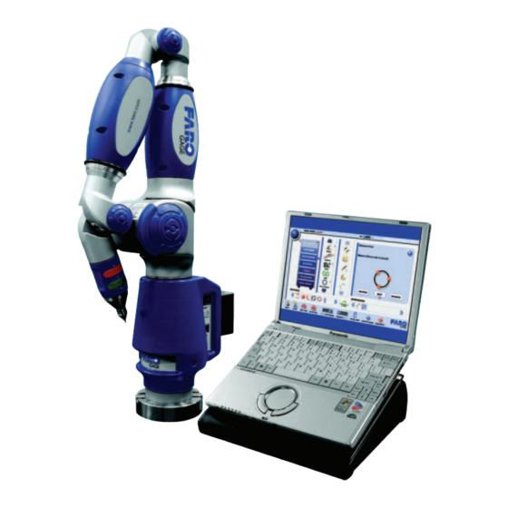
- Page 11 Objective: Learn the basic FARO Gage system setup procedure, familiarize yourself with the screen layout, and calibrate the probe. Setup The FARO Gage must be mounted in an upright position. Do not mount the FARO Gage in an inverted (upside-down) or sideways position. To fasten the FARO Gage: 1 Attach the 3.5"...
- Page 12 3 - USB Cable 4 - Power Supply 5 - Power Outlet 6 Switch on the FARO Gage and then the Gage computer. 7 The FARO Gage software will launch automatically after you have turned on the computer. Chapter 1: Getting Started...
-
Page 13: Hardware Operation
Version 1.5 - August 2007 Hardware Operation The FARO Gage has two sets of buttons. The GREEN (Front) button is used to collect data, and the RED (back) button to accept the data. When a button is pressed, the LED light illuminates (red or green). -
Page 14: Software Modes
The FARO Gage software operates in two separate modes: GAGE and METROLOGY. GAGE mode is designed for quick measurement of simple parts; METROLOGY mode is designed for measurement of larger and more complex parts, or if you measure many different parts each day. - Page 15 Screen Layout (General) 1 ABOUT button • Displays the current version of the software. 2 Toolbox - The main FARO Gage software menu is displayed as a Toolbox. • Each "Drawer" of the Toolbox opens into specific functions. • Scroll up and down in each Drawer menu to display additional items.
- Page 16 Select the CLEAR TOOLS button to erase all tools from the tools list. 8 GAGE/METROLOGY switch • Select the GAGE/METROLOGY switch to toggle between GAGE and METROLOGY modes. : Switching between GAGE and METROLOGY modes will reset the tool file. 9 CALCULATOR • Launches the MS Windows® Calculator. 10 QUICK START GUIDE •...
- Page 17 Basic Training Workbook Version 1.5 - August 2007 Screen Layout (Gage Mode) 1 Tools List • An icon for each tool you use will be displayed here to keep record of your work. 2 PRINT Button • Select to generate and print a report.
- Page 18 Basic Training Workbook Version 1.5 - August 2007 Screen Layout (Metrology Mode) 1 Features List • An icon for each feature you use will be displayed here, keeping record of your work. • Existing commands in the current tool file show up in the order that they are entered. •...
-
Page 19: What Is Calibration
Probe Calibration The FARO Gage collects data with a probe attached to the end of the handle. Once the probe is attached, the location of the probe tip relative to the Gage's coordinate system must be determined prior to measuring, hence the need for probe calibration. - Page 20 Practical - Calibration Securely attach the FARO Probe Calibration cone near the FARO Gage. For best results, position the calibration cone approximately 2/3 of the Gage arm's reach away from the base. 1 Choose Gage Setup < Probe Calibration. 2 Select the RUN button.
- Page 21 : All of the points in this method will be collected by holding down the GREEN button. The FARO Gage will collect points as fast as possible (scanning) until you release the GREEN button. 6 Place the ball probe in the hole. Start in a vertical position.
- Page 22 If you calibrate the probe correctly, the calibration status changes to PASS. • If the probe calibration fails, select the RETRY button and repeat the calibration until the probe passes. You are now ready to measure with the FARO Gage. Chapter 1: Getting Started...
- Page 23 CUSTOM TOOLS - Save, load, and run your tools. Measuring To measure with the FARO Gage, make sure you’re in GAGE mode (switch to GAGE mode, select OK), choose a tool, and follow the on-screen pictures and text prompts. The basic geometry illustration shows how a specific features needs to be measured, and the text prompt below indicates the minimum number of points that you will need to collect.
- Page 24 RED button. : When you press the RED button, the location of the probe is critical. The FARO Gage uses a ball probe to measure and all measurements are taken from the center of the probe. To compensate the measurements for the ball probe radius, points must be digitized off the feature.
- Page 25 : In GAGE mode, you are not able to save a tool list. Shutting down Gage software erases all active tools and resets your tool list. Measurement results are saved automatically. You can review your results and print a report using the PRINT button.
- Page 26 Angle - Edge to Edge Use the Edge to Edge command to dimension the angle between two edges. The angle is the smallest angle. You may use the FARO Training part or your own part. 1 Select the TOOLS drawer in the Toolbox.
- Page 27 Digitize 2 or more points on the edge. Note the direction in which you take the points. • Pull away from the part and digitize 1 point with the RED button to complete the command. Chapter 2: Basic Measurements (Gage Mode)
- Page 28 You may type any Nominal and Tolerance values for the angle. 9 Select OK to add the angle to your FARO Gage tool list. : The angle reported will always be the smallest angle based on the positive ends of your measurement direction.
- Page 29 (The picture on the right depicts how you would measure a cylindrical pin. • Pull away from the part and digitize 1 point with the RED button to complete the command. Chapter 2: Basic Measurements (Gage Mode)
- Page 30 8 View the results of your measurement in the R dialog box. ESULTS • You may type any Nominal and Tolerance values for the distance. 9 Select OK to add the distance to your FARO Gage tool list. Chapter 2: Basic Measurements (Gage Mode)
- Page 31 Place the ball probe on the part and digitize points with the GREEN button. • Digitize 3 or more points on the planar surface. • Pull away from the part and digitize 1 point with the RED button to complete the command. Chapter 2: Basic Measurements (Gage Mode)
- Page 32 7 View the results of your measurement in the R dialog box. ESULTS • You may type any nominal and tolerance values for the feature. 8 Select OK to add the feature to your FARO Gage tool list. Chapter 2: Basic Measurements (Gage Mode)
- Page 33 Place the ball probe on the part and digitize points with the GREEN button. • Digitize 3 or more points on the planar surface. • Pull away from the part and digitize 1 point with the RED button to complete the command. Chapter 2: Basic Measurements (Gage Mode)
- Page 34 The FARO Gage 3D Caliper command replaces a traditional height gage tool by providing a quick distance measurement. You must setup a base face (measurement table, gage block, etc.) and touch your part to check the distance from the base face to the surface on the part.
- Page 35 Manual compensation allows you to touch the surface in any position. Part Away Towards Away Base Face • AWAY FROM BASE compensates when the surface faces away from the base face. • TOWARD BASE compensates when the surface faces the base face. Chapter 2: Basic Measurements (Gage Mode)
- Page 36 2 Select the SET button for the X, Y, or Z base face and measure base face (table). 3 After setting the base face, place the FARO Gage probe on top of your part. Look at the screen to see the height from the base face to the surface.
- Page 37 4 Press the GREEN button to unfreeze the display. 5 Place the FARO Gage probe on your part. Look at the screen to see the height from the base face to the probe, and the height from the temporary zero height to the probe.
- Page 38 : Pressing the GREEN button to freeze and unfreeze the display is optional. Press and Hold the RED button to clear the temporary zero height. You can repeat these steps at another height. 6 Select the CLOSE button. Chapter 2: Basic Measurements (Gage Mode)
- Page 39 Features drawer is only available in METROLOGY mode. Types of Features There are two basic types of features in Gage software: 2D and 3D. 2D features are flat features that require a base face or plane of projection. 3D features have some depth and do not require a plane of projection.
- Page 40 You will always need to select the face to which the points will be projected. : Gage software will automatically add the prefix "M_" to all measured features to indicate that these are measured features. Chapter 3: Feature Measurements (Metrology Mode)
- Page 41 Basic Training Workbook Version 1.5 - August 2007 Practical - Measuring Features Face Use the Face command to measure a face (planar surface) on your part. The face measurement best-fits a face using digitized points. Make sure you’re in Metrology Mode (select the Metrology switch, and select OK). 1 Select the FEATURES drawer in the Toolbox.
- Page 42 • The nominal value for the face form is 0. 8 Select OK to add the face to your FARO Gage part file. 9 When prompted to measure the next face, select CANCEL. : All feature commands are set to auto-repeat.
- Page 43 Basic Training Workbook Version 1.5 - August 2007 Edge (2D) Use the 2D command to measure an edge (straight line) on your part. The edge measurement best-fits an edge through digitized points. 1 Select the FEATURES drawer in the Toolbox. 2 Select the EDGE group.
- Page 44 9 View the results of your measurement in the R dialog box. ESULTS Positive Direction 10 Select OK to add the edge to your FARO Gage part file. 11 When prompted to measure the next edge, select CANCEL. Chapter 3: Feature Measurements (Metrology Mode)
- Page 45 Basic Training Workbook Version 1.5 - August 2007 Hole Use the Hole command to measure a hole, circle, or post on your part. The hole measurement best-fits a hole through digitized points. 1 Select the FEATURES drawer in the Toolbox. 2 Select the Hole command.
- Page 46 ESULTS 9 Type Nominal diameter = 100 and Tolerance = +0.25, -0.10. 10 Select OK to add the hole to your FARO Gage part file. 11 When prompted to measure the next hole, select CANCEL. Chapter 3: Feature Measurements (Metrology Mode)
- Page 47 If this cone is a datum of your part, select the DATUM check box. 5 Select OK to measure the cone. 6 Measure the cone with the FARO Gage. • Place the ball probe on the part and digitize points with the GREEN button.
-
Page 48: Review Results
ESULTS 8 Type Nominal angle = 15 and Tolerance = +/-1 values for the cone. 9 Select OK to add the cone to your FARO Gage part file. 10 When prompted to measure the next cone, select CANCEL. Review Results Select any F icon from the Features List to review the measurement data. - Page 49 Metrology mode. Dimensions The FARO Gage Dimensions drawer contains all the commands for creating dimensions using existing features. Dimensions are often the values that are listed on the design print for your part. The Dimensions commands are organized into the ANGLE, LENGTH, GD&T, DRO, BUILD HOLE, BUILD EDGE, BUILD FACE, and BUILD POINT groups within the Dimensions drawer.
- Page 50 Basic Training Workbook Version 1.5 - August 2007 Feature Reducibility Table Plane Line Point Circle Cylinder Cone Ellipse Line Plane Point Chapter 4: Basic Part Measurements (Metrology Mode)
- Page 51 In FARO Gage, the coordinate system of the measured features can be aligned with the coordinate system of nominal features, allowing you to compare the measured part to the design data.
- Page 52 2 points for a line or axis and 1 point is the origin). FARO Gage software has a smart alignment feature that recognizes when you have met the minimum requirements to create a coordinate system and also tries to determine whether they should be used based on the available features.
- Page 53 A dimension describes the relationship between two or more features. There are several types of dimensions available in FARO Gage, such as: 1 Length: Displays the 3D distance between two features as well as the change in X, Y and >...
- Page 54 Basic Training Workbook Version 1.5 - August 2007 Tricky Dimensions Most GAGE dimensions are fairly straight forward, but there are few that might be confusing: • Edge to Edge • Face to Face This gives the minimum distance between two features. The length is measured from the center point of one feature to the perpendicular distance of the other feature.
- Page 55 2 Circle: Best-fit - Bolt circle diameters. Review the constructions to evaluate which commands can be applied to a measurement task. : Gage software will automatically add the prefix "C_" to all dimensions, alignments and built features to indicate that these are constructed features.
-
Page 56: Setting The Alignment
Basic Training Workbook Version 1.5 - August 2007 Practical - Basic Part Measurements (Metrology Mode) For this practical, we will use the FARO Demo/Training part and the following prints: [.787] [2.56] .50 B [6.575] [5.118] [1.969] [1.969] [.787] [.591] [2.559] [.787]... - Page 57 7 Type a name for your measured face (or use the default name). 8 Select the DATUM check box and choose A. 9 Select OK to measure the face. 10 Measure the face with the FARO Gage. • Place the ball probe on the part and digitize points with the GREEN button.
- Page 58 11 View the results of your measurement in the R dialog box. ESULTS 12 Select OK to add the face to your FARO Gage part file. • This will be your XY plane. (Z axis) 13 Select the CANCEL button to exit the command.
- Page 59 ESULTS Positive Direction 23 Select OK to add the edge to your FARO Gage part file. • This will be your X axis. The direction in which you take the points will determine the direction of the axis.
- Page 60 29 Select the DATUM check box and choose C. 30 Select OK to measure Hole #9. 31 Measure the center hole with the FARO Gage. • Place the ball probe on the part and digitize points with the GREEN button.
- Page 61 ESULTS 33 Type Nominal diameter = 100 and Tolerance = +0.25, -0.10. 34 Select OK to add the hole to your FARO Gage part file. • This will be your 0,0,0 coordinate system origin. 35 Select the CANCEL button.
- Page 62 Basic Training Workbook Version 1.5 - August 2007 38 Select the features. • The software should have pre-selected the face for the first feature, the edge for the second and the hole for the third feature. 39 Select OK to complete the alignment. : The alignment icon will now display a red and blue arrow indicating that an alignment is present.
- Page 63 Basic Training Workbook Version 1.5 - August 2007 Verifying the Alignment To verify that the alignment orientation was properly set, select 3D CALIPER, select the SETUP tab, select the USE ALIGNMENT check box, then select the 3D tab. Observe the X,Y,Z readings as you move the probe around the part.
- Page 64 Basic Training Workbook Version 1.5 - August 2007 6 Measure the center hole with the FARO Gage. • Place the ball probe on the part and digitize points with the GREEN button. • Digitize 3 or more points in the hole.
- Page 65 Let’s check the bolt circle specified on the print. The eight 20mm holes are equally spaced in a 140mm bolt circle which cannot be measured directly with the FARO Gage. We'll use the build command to create it from the four previously measured 20mm holes.
- Page 66 Basic Training Workbook Version 1.5 - August 2007 NOTE: Use the Best Fit command to build a best-fit hole from previously measured features and/or dimensions. The Best Fit command builds a best-fit hole from existing features and/or dimensions. The points project to the face before the best-fit calculation starts. 5 Type a name for your dimension, or use the default name.
- Page 67 Version 1.5 - August 2007 10 Type Nominal Diameter = 140 and Tolerance = +0.25, -0.10. 11 Select OK to add the hole to your FARO Gage part file. Dimensions Let's check the distance between the center of the bolt circle and Datum Edge B. Use the Point To Edge command to build a length between a point and an edge.
- Page 68 9 View the results of your dimension. 10 Type Nominal Length = 65 and Tolerance = +/-0.25. 11 Select OK to add the dimension to your FARO Gage part file. GD&T (Optional) Let's check the Position of the 20mm holes. Use the Position command to measure the GD&T Position of an existing feature.
- Page 69 REVIEW. You can also edit the nominal information or remove features from the list. The FARO Gage Reports drawer contains all the commands to create reports for your part. The Reports drawer is only available in METROLOGY mode.
- Page 70 Basic Training Workbook Version 1.5 - August 2007 Use the Tabular command to create a report of the features and dimensions on your part. 1 Select the REPORTS drawer in the Toolbox. 2 Select the NEW REPORT group. 3 Select the Tabular command. 4 Select the RUN button.
- Page 71 Basic Training Workbook Version 1.5 - August 2007 There are two additional report formats in FARO Gage: Excel and SPC. Use these to create output files that can easily be imported to other applications for data analysis. Both the Excel and SPC formats will create .csv text files. They are both saved automatically to C:\DOCUMENTS AND SETTINGS\ALL USERS\APPLICATION DATA\FARO\CAM2 MEASURE\EXCEL.
- Page 72 Basic Training Workbook Version 1.5 - August 2007 6 Select the PICK PICTURE tab and choose a picture, or use the default picture. : Select the NAMES radio button to see the names of the pictures in a list. 7 Select the OK button to save the tool. Load Custom Tool Use the Load command to open a saved tool for your part.
- Page 73 Basic Training Workbook Version 1.5 - August 2007 6 Select the OK button to load the tool. Run Custom Tool Use the Run command to reset a saved tool to the beginning, which will take you through the measurement routine to measure another part. 1 Select the TOOLS drawer in the Toolbox.
-
Page 76: Contact Information
Contact Information For Technical Support World Wide Web site: www.faro.com E-mail: support@faro.com Telephone Number: 800.736.2771 For Sales Inquiries Electronic Product Catalog on www.faro.com E-mail: info@faro.com Telephone Number: 800.736.0234, extension 2265 For Training or Technical Services E-mail: training@faro.com Telephone Number: 800.736.0234, extension 1111...
Need help?
Do you have a question about the Gage and is the answer not in the manual?
Questions and answers