
Related Manuals for Faro FaroArm Quantum


Summary of Contents for Faro FaroArm Quantum
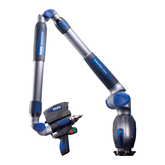
- Page 1 ® FaroArm Manual January 2009 Includes Quantum, Platinum, Fusion ® and ScanArm Models...
- Page 3 ANYONE FOR SPECIAL, COLLATERAL, INCIDENTAL, OR CONSEQUENTIAL DAMAGES IN CONNECTION WITH OR ARISING OUT OF THE PURCHASE OR USE OF THE FARO ARM OR ITS MATERIALS. THE SOLE AND EXCLUSIVE LIABILITY TO FARO TECHNOLOGIES INC., REGARDLESS OF THE FORM OF ACTION, SHALL NOT EXCEED THE PURCHASE PRICE OF THE MATERIALS DESCRIBED HEREIN.
-
Page 5: Table Of Contents
Platinum/Fusion Series TP-20 Probe Kit ........22 Probe Modules for the TP-20 Probe .......... 23 Measuring Software ..............24 Custom Probe Calibration............24 FARO Laser Line Probe ..........25 Laser Safety ..................25 Laser Radiation Emission ............... 25 Serial Number Label ..............27 Servicing .................. - Page 6 Charging the Battery Pack ............58 Troubleshooting ............. 59 Power Issues..................60 Hardware Communication Issues..........61 FARO Wireless Connection Issues ..........62 FARO Wireless FAQ ................ 63 FARO i-Probe FAQ ................. 64 FaroArm/ScanArm Performance Verification Checklist ... 66 Issues That Will Degrade Accuracy .......... 66...
- Page 7 ® FaroArm Manual January 2009 Probe Setup ................67 Probe Calibration ..............68 Mounting ..................69 Single Point Articulation Test (SPAT).......... 70 Calibrated Artifact ..............71 Diagnosing Laser Line Probe Accuracy Problems....71 Laser Line Probe Calibration ............. 73 Chapter 2 : CAM2® Measure Devices Menu Device Setup ..............
-
Page 9: Chapter 1: Introduction To The Faroarm
Customer Service Representative by Phone, Fax or E-Mail. See “Technical Support” on page 93. Visit the FARO Customer Service area on the Web at www.faro.com to search our technical support database. The database is available 24 hours a day, 7 days a week, and contains hundreds of solutions to product and application questions. -
Page 10: General Information
® FaroArm Manual January 2009 You may also see a few new words. It is important that you understand the meaning of these words before proceeding. digitize To record the XYZ coordinates of a point or location in 3D space. The word digitize is the same as the term measure when referring to points. -
Page 11: Precautions
• Two probes • Renishaw Adapter (Quantum series only) • FARO Calibration Cone • 12mm wrench • FARO probe torque wrench (Quantum series only) • Mounting screws in a plastic case • Hex wrench for the mounting screws • USB cable •... -
Page 12: Optional Accessories
FARO. Installation and detailed operational instructions are included. The Accessories Manual is also available on FARO’s Web site at www.faro.com. To purchase optional accessories, contact FARO’s Customer Service by Phone, Fax or E-Mail. See “Technical Support”... -
Page 13: Packing The Faroarm
® FaroArm Manual January 2009 Packing the FaroArm The FaroArm should be packed very carefully to prevent shipping damage. 1 Pack the Power Supply, Probe Case, and Surface Mount Plate as shown. Figure 1-1 Pack the Power Module, Probe Case, and Surface Mount Plate Chapter 1: Introduction to the FaroArm ®... -
Page 14: Hardware Setup
® FaroArm Manual January 2009 2 Grasp the FaroArm with both hands as shown. 3 Insert the FaroArm into the case. Figure 1-2 Insert the FaroArm into the Case Hardware Setup The following sections describe the proper setup of the FaroArm system. -
Page 15: Surface Mount Plate Dimensions
The Surface Mount Plate is used to clamp or bolt the FaroArm to a stable mounting surface. It is an assembly of a standard 3½” mounting ring and a FARO designed base plate. Chapter 1: Introduction to the FaroArm ®... - Page 16 ® FaroArm Manual January 2009 You can bolt the Surface Mount Plate directly to a surface using the mounting screws in the probe case. Make sure to tighten each mounting screw with the hex wrench. .001 .001 5.187 .12 X 45 CHAMFER 2.970 5.950...
-
Page 17: Host Computer
FaroArm USB port FaroArm USB port : For optimum performance, allow the FaroArm to warm-up for at least 30 minutes before using. FARO Wireless ® The FaroArm is a Bluetooth equipped device and can connect to your computer without using a USB cable. - Page 18 • Software supplied with a Bluetooth equipped computer, or an aftermarket USB Bluetooth dongle and software. • FARO Bluetooth Connection Setup utility software. : Implementation will differ among software suppliers, but generally there is a platform specific Bluetooth Wizard that will search for all Bluetooth devices in range and display them graphically, or in a simple list.
- Page 19 The FaroArm USB driver connects to the SPP connection using the FARO Bluetooth Connection Setup utility software. Figure 1-10 Connecting the FaroArm to the Computer • Start FARO Bluetooth Connection Setup utility software program. • Click the NEW button. Figure 1-11 Connection Name and COM port •...
- Page 20 : If you choose not to connect the FaroArm to your computer using the wireless connection, deselect the icon check box in the FARO Bluetooth Connection Setup utility to deactivate the pairing and connect using the USB cable. Once you start measuring, there is no difference in data transfer between using the Bluetooth connection or the USB cable.
-
Page 21: Numerical And Signal Processing
® FaroArm Manual January 2009 Numerical and Signal Processing The FaroArm includes a complete electronics system located within the body of the FaroArm. Signals from each joint are processed and positional data is sent out to the computer. : The FaroArm electronics go into standby mode, or turn off, after two hours of no encoder movement. -
Page 22: Error And Status Indicators
® FaroArm Manual January 2009 Error and Status Indicators Through the driver interface to the measuring software, the FaroArm generates and displays errors in the E dialog TRESS ARNING box. • The encoder end stop warnings - This warning appears when an encoder reaches one end of its rotation. - Page 23 FaroArm Manual January 2009 • The unknown FARO i-Probe warning - This warning appears when a FARO i-Probe is attached to a Quantum series FaroArm and never calibrated. For accurate measuring, you must calibrate the probe. Use your measuring software to setup and calibrate the probe. See “Probes”...
-
Page 24: Referencing The Encoders
® FaroArm Manual January 2009 Referencing the Encoders You must reference each of the six (or seven) encoders in the FaroArm before the system can output data. The R dialog EFERENCE NCODERS box shows all six encoders in error until each is referenced. In a systematic manner, rotate joints 1 through 6 (7) until each warning clears. -
Page 25: Faroarm Handle Buttons
® FaroArm Manual January 2009 FaroArm Handle Buttons The FaroArm has two sets of two buttons and an LED, where the FRONT buttons and BACK buttons are redundant and wired together internally. When a button is pressed, the LED light turns on (green or red) and the Computer sounds. -
Page 26: Auxiliary Port (7Th Variable Options Port)
Auxiliary Port (7th Variable Options Port) On the side of the FaroArm base, an optional communications port is available to connect external equipment. To get a list of approved FARO devices, contact your Customer Service Representative by Phone, Fax or E-Mail. See “Technical Support” on page 93. -
Page 27: Faroarm Probes
FaroArm and monitors probe body temperature to compensate for thermal deformation. : FARO i-Probes will not attach to Platinum or Fusion series FaroArms. Installing the i-Probe to anything other than a Quantum series FaroArm damages the i-Probe. -
Page 28: Custom Probes
24.9 ø10 • The FaroArm Probe thread size is 1¼-20. • The base of the probe should 62˚ follow the shape of the FARO 28˚ R 0.5 probes. 11.85 Your custom probe should be as rigid as possible. Any deflection in the probe will add inaccuracy to the FaroArm system. -
Page 29: Installing Probes
The probe attaches to the threaded handle at the end of the FaroArm. Use the 12mm wrench in the probe case to install the probe. : Use the FARO probe torque wrench to tighten the FARO i- Probe. The probe wrench will break free when you apply the proper amount of torque. -
Page 30: Renishaw Tp-20 Probe Installation And Operation
: The Renishaw TP-2 Probe is not supported. Quantum Series The Quantum series FaroArm uses the FARO i-Probe adapter to connect the TP-20 probe module to the FaroArm handle. Simply attach this assembly just as you would any other probe. See “Installing Probes” on page 21. -
Page 31: Probe Modules For The Tp-20 Probe
® FaroArm Manual January 2009 • Renishaw (CK200) cleaning kit • A magnetized TP-20 probe body • Three separate magnetized TP-20 probe modules, which connect to the TP-20 probe body. : The product numbers in the parentheses are Renishaw part numbers. -
Page 32: Measuring Software
® FaroArm Manual January 2009 • Standard Force Probe Module (Black cap) • Medium Force Probe Module (Gray cap) • Extended Force Probe Module (Brown cap) Refer to the Renishaw TP-20 Installation and User’s Manual for the TP- 20 Probe assembly instructions. Measuring Software The measuring software must be configured for the probe. -
Page 33: Faro Laser Line Probe
Laser Radiation Emission When the FARO Laser Line Probe is operating, a laser beam emits from the aperture at the front of the FARO Laser Line Probe. See Figure 1-23 for the location of the laser beam aperture. AVOID EXPOSURE... - Page 34 POSE AN EYE HAZARD. Laser power up to 5 mW at 660 nm in a diverging beam could be accessible in the interior of the FARO Laser Line Probe. WARNING: DO NOT ATTEMPT TO OPEN THE LASER LINE PROBE CASE. THERE ARE NO USER SERVICABLE PARTS.
-
Page 35: Serial Number Label
If the Laser Line Probe is not operating properly, contact FARO Customer Support. If it has malfunctioned, power down the system, remove it from the FaroArm and return it to FARO Customer Support for repair. WARNING: DO NOT ATTEMPT TO OPEN THE LASER LINE PROBE CASE. -
Page 36: Hardware Installation
Manual January 2009 Hardware Installation Installing the FARO Laser Line Probe is similar to any other FaroArm probe. However, there is a Trim Ring on the end of the handle that must be removed for the Laser Line Probe to install correctly. - Page 37 7 Connect the plug from the Laser Line Probe to the options port. The options port is located on the back of the FaroArm handle. Tighten the threaded connector. Figure 1-27 Install the FARO Laser Line Probe CAUTION: Before inserting the connector, make sure that the power is OFF.
-
Page 38: Holding The Laser Line Probe
Laser Line Probe case. Dirt and grease on either lens can cause poor results. Hardware Controls and Indicators The FaroArm/FARO Laser Line Probe system uses the FRONT (Green) and BACK (Red) and two LEDs on the back of the Laser Line Probe. Buttons Use the FRONT (green) button to start data collection. -
Page 39: Leds
INDER position from the Laser Line Probe to your part. Range Finder The FARO Laser Line Probe software has a R dialog box. ANGE INDER This dialog box graphically displays the laser to part distance and the area of the laser line that the camera is processing. -
Page 40: Software Setup
The FaroArm/FARO Laser Line Probe system can be used with many software packages. Refer to the particular application software for installation and proper use of the software with the FARO Laser Line Probe. : Some software packages automatically add the FaroArm software driver to your computer. - Page 41 ® FaroArm Manual January 2009 2 Choose a standard ball probe, 6mm or 3mm. Figure 1-31 Standard Ball Probe : If your ball probes are stamped with the exact diameter, enter the exact diameter in the M dialog box for each ball ODIFY ROBE probe.
-
Page 42: Sphere Calibration
® FaroArm Manual January 2009 Sphere Calibration Calibrate the FARO Laser Line Probe. You will digitize 24 points in three positions. Position #1 Position #2 Position #3 Figure 1-33 Calibration Positions : Avoid touching both lenses. Clean the top and bottom lenses with the cloth from the Laser Line Probe case. - Page 43 ® FaroArm Manual January 2009 2 Digitize eight points on a side of the calibration sphere with the Laser Line Probe pointing in position #2, see Figure 1-33. Digitize two points in the Near range with the center of the laser. One point on the upper half of the calibration sphere and the other on the lower half.
- Page 44 ® FaroArm Manual January 2009 3 Digitize eight points on the front of the calibration sphere with the Laser Line Probe pointing in position #3, see Figure 1-33. Digitize two points in the Near range with the center of the laser. One point on the upper half of the calibration sphere and the other on the lower half.
-
Page 45: Plane Calibration
Manual January 2009 Plane Calibration Calibrate the FARO Laser Line Probe. You will digitize the FARO Calibration Plate, once with the ball probe, and then three times with the Laser Line Probe. 1 Digitize the White area of the Calibration Plate with the ball probe. - Page 46 ® FaroArm Manual January 2009 2 Digitize the white area of the Calibration Plate with the Laser Line Probe in a sweeping motion. You should collect at least 200 scan lines in the Laser Line Probe calibration. If not, repeat the calibration moving the Laser Line Probe slower in each step.
-
Page 47: Dro
The DRO window displays the current location of the probe in the current coordinate system. • If the FARO Laser Line Probe is in range, the X, Y, Z coordinate is the center of the laser line. Note that this may not be the center of the complete laser line because some part of the laser line may be out of range. -
Page 48: Laser Line Probe Settings
FaroArm Manual January 2009 • If the FARO Laser Line Probe is out of range, then no coordinate is available and the DRO displays a row of asterisks (******). Laser Line Probe Settings Modify the settings of the FARO Laser Line Probe for your part. The default settings are for digitizing the calibration sphere or plane that has an opaque white surface. -
Page 49: Line Probe Settings
In the M dialog box, you will see all of the information ODIFY ROBE about the FARO Laser Line Probe. Figure 1-35 Modify Probe dialog box • Click the SCANNER SETTINGS button to modify the settings of the FARO Laser Line Probe. - Page 50 : Adding all visible light to the preview window will decrease the number of frames per second sent to the computer and should only be used when diagnosing problems with the FARO Laser Line Probe. • Select the H check box to operate the Laser CCURACY Line Probe in the High Accuracy mode.
- Page 51 ® FaroArm Manual January 2009 pointing at the surface, until the process completes. You can also set the values manually: • Exposure - How long the “shutter” is open and the sensor is exposed to light in the camera. Enter a number from 1 to 80; the corresponding value in milliseconds appears next to it.
- Page 52 ® FaroArm Manual January 2009 automatic mode uses the entire exposure range of the Laser Line Probe. In this mode, you may notice a slight decrease in speed as the Laser Line Probe automatically adjusts from one surface type to another. •...
-
Page 53: Additional Considerations
® FaroArm Manual January 2009 Keep in mind that given the vast range of colors, textures and finishes, there is no exact science for these Line Probe Settings that work best on a particular surface. Finding the optimum settings may require some practice. -
Page 54: Faroarm Calibration
The FaroArm will only lose its calibration (stop functioning within FARO's published standards) if one or more of the following occurs: • Bending of the transfer cases (long, tube sections). • Damage to the encoder-bearing interface joints (where tubes, bearings and encoders are mated). -
Page 55: Repeatability
Minimum measurement divided by two (Max.-Min.)/2. If any test fails, print the results and repeat the certification two more times. Print all of the results and contact FARO’s Customer Service by Phone, Fax or E-Mail. See “Technical Support” on page 93. -
Page 56: Volumetric Accuracy
X, Y, Z. This test is a method for determining articulating measurement machine repeatability. • FARO reports this as (Max.-Min.)/2. This represents the error as the range of error between the least value and the highest value. - Page 57 ® FaroArm Manual January 2009 The specifications of your FaroArm are listed on the serial number label on the left side of the base. Cer tification Cer tification P08-02-07-05675 Aug18, 2007 Date Date Model Model +/- .025 mm. Single Point Single Point 26.2 +/- .036 mm.
-
Page 58: Loss Of A Degree Of Freedom
® FaroArm Manual January 2009 Loss of a Degree of Freedom In a working volume of the FaroArm there can be a loss of a degree of freedom (natural rotation of transfer case). With this loss, temporary bending occurs on the transfer tubes of the FaroArm causing a movement of the probe position that cannot be recorded by the Arm’s encoder system. -
Page 59: Normal Maintenance
FaroArm accuracy and repeatability. See “FaroArm Certification” on page 46. FARO recommends you return your FaroArm to a service center, once a year, for our annual certification and a 15 point check up. -
Page 60: Mounting Stiffness Test
® FaroArm Manual January 2009 • Do not use an AC adapter other than the one supplied with the computer. • Do not push on the LCD screen excessively or subject it to shocks. • Do not expose the LCD screen to direct sunlight, even through a window. -
Page 61: Temperature Considerations
Temperature Considerations FARO was awarded the U.S. patent #5,402,582, and worldwide patents are pending, on the concept and the methods for temperature compensation of portable CMM devices. This brief overview is meant only as the most general of descriptions. -
Page 62: Electrostatic Discharge (Esd)
® FaroArm Manual January 2009 the kinematics and constantly adapts the output to changing environmental temperature. However, because different components heat or cool at different rates, the device is expected to reach a steady state temperature within a ±3 degree (Celsius) bandwidth for five minutes before measurements can be taken. - Page 63 ® FaroArm Manual January 2009 means of a Conductive Flooring. When seated, heel straps do not offer the protections required to dissipate a static charge. ESD Lotion - ESD lotion provides a better connection between the user and a smock, heel strap or wrist strap. This may need to be reapplied if the smock or straps are removed.
-
Page 64: Faroarm Power Supply
NRTL Listed for US and Canada. For IEC member countries and Europe, the power supply must be certified for the country in which the equipment is sold. Contact FARO’s Customer Service to order a replacement. All servicing should be referred to qualified service personnel. -
Page 65: Faroarm Battery Pack
® FaroArm Manual January 2009 • For 120V Connection: Use a UL Listed, type SJT or SVT, 3- Conductor, 18 A.W.G. power supply cord, terminating in a molded-on plug cap rated 125 VAC, 15A minimum, with a minimum length of six feet. -
Page 66: Removing The Battery Pack
WARNING: Only use the rechargeable battery pack supplied with your FaroArm. For information on ordering additional or replacement battery packs, contact FARO’s Customer Service by Phone, Fax or E- Mail. See “Technical Support” on page 93. Chapter 1: Introduction to the FaroArm... -
Page 67: Troubleshooting
January 2009 Troubleshooting Error message on host computer. • Contact FARO’s Customer Service by Phone, Fax or E-Mail. See “Technical Support” on page 93. Have the message ready. Probe calibration fails. • Check that the diameter stamped on the probe tip matches the tip of the current probe. -
Page 68: Power Issues
® FaroArm Manual January 2009 FaroArm records points without pressing either button. • Re-seat the set screw in the FaroArm handle. If the set screw is not seated correctly it causes intermittent contact to the pin underneath, and random points are taken. Figure 1-43 Handle Screw 1 Remove any standard FaroArm probe. -
Page 69: Hardware Communication Issues
PDAs, digital cameras, scanners, zip drives, modems and external devices are know to cause these conflicts. • Check that only the Faro Arm software is running on the computer. Ensure multiple sessions of the measuring software is not running. -
Page 70: Faro Wireless Connection Issues
4 Open the platform specific Bluetooth Wizard and check which COM port is configured with the FaroArm. 5 Open the FARO Bluetooth Connection Setup utility program and confirm the COM port setting. Ensure it matches the same port in the platform specific Bluetooth Wizard list. -
Page 71: Faro Wireless Faq
USB cable at the same time? No. If both are properly connected, the Bluetooth wireless will be the only active connection for that FaroArm. • Can I use a FARO Laser Line Probe with the FARO Wireless connection? Yes. • Can I add a Bluetooth wireless connection while the FaroArm driver... -
Page 72: Faro I-Probe Faq
Once the FaroArm driver detects that the FaroArm is no longer connected, after about 10 seconds, a message appears asking if you want to restore the FARO Wireless connection. If you click No, the connection stops. If you click Yes, attempts are made to restore the connection. - Page 73 ® FaroArm Manual January 2009 • I have an i-Probe attached but see this error dialog box and can not measure. What is wrong? Ensure that the i-Probe is threaded on all the way. If the system still does not recognize it, the i-Probe may be damaged and may need to be replaced.
-
Page 74: Faroarm/Scanarm Performance Verification Checklist
® FaroArm Manual January 2009 FaroArm/ScanArm Performance Verification Checklist If you are experiencing accuracy or repeatability problems with your FaroArm or ScanArm system, this section details proper setup techniques to help you identify the potential sources of error. It is important to clearly understand all the “do's and don'ts” in order to get the most out of every FaroArm and ScanArm system. -
Page 75: Faroarm Setup
® FaroArm Manual January 2009 Measurement Environment 1 Measuring close to an end stop can induce unwanted stress. 2 Binding or hyper-extending the arm can cause unnecessary stress. 3 “Leap Frogging” or repositioning the device using the Move Device Position command. 4 Excessive vibration in the surrounding area can produce unwanted results. -
Page 76: Probe Calibration
® FaroArm Manual January 2009 Probe Calibration Place the calibration cone approximately 2/3 of the FaroArm's reach away from its base. Perform the probe calibration at least 3 times. For more information, see “Single Hole Method” on page 83. Look in the probe calibration log and compare the X, Y and Z values. -
Page 77: Mounting
® FaroArm Manual January 2009 Mounting Most accuracy and repeatability problems can be attributed to improper mounting of the arm. These issues are not always obvious. An apparently stable mount can actually be moving more than the accuracy of the device, directly impacting results and causing system performance degradation. -
Page 78: Single Point Articulation Test (Spat)
® FaroArm Manual January 2009 Single Point Articulation Test (SPAT) Mounting should always be tested prior to a SPAT test. The SPAT test checks the repeatability of the FaroArm's X, Y and Z coordinates throughout its range of motion. In CAM2 Measure, launch the Perform SPAT routine from the dialog box. -
Page 79: Calibrated Artifact
® FaroArm Manual January 2009 Calibrated Artifact Measure an artifact of certified dimensions (i.e.: ring gage or gage block). Ring Gage should be measured as a cylinder. Gage Block should be measured plane-to- plane, or point-to-plane (surface point). : The dimension of calibrated artifacts is usually specified at a temperature of 20°C (68°F). - Page 80 ® FaroArm Manual January 2009 Clean the top and bottom lenses with the cloth from the Laser Line Probe case. Dirt and grease on either lens can cause poor results. Place the calibration plate approximate 2/3 of the FaroArm's reach away from its base.
-
Page 81: Laser Line Probe Calibration
® FaroArm Manual January 2009 Laser Line Probe Calibration Ensure the Scan Rate and Scan Density are set 1/1. From the host application select "Scanner Options" or "Scanner Controls" to access the settings dialog box. Perform the calibration at least 3 times. See “Calibration” on page 32. - Page 82 ® FaroArm Manual January 2009 When sweeping from side to side and front to back, make sure you sweep through at least 90 degrees. Typically, you should take about 200 scans during the calibration process. In the probe calibration log, look at the X, Y, Z, A, B, C values. Each value should repeat to within: X: 100 microns A: 0.1 degrees Y: 50 microns...
-
Page 83: Chapter 2: Cam2® Measure Devices Menu
® FaroArm Manual January 2009 ® Chapter 2: CAM2 Measure Devices Menu The DEVICES menu contains all the commands used to configure a measuring device. These commands are also available on the Devices toolbar. Device Setup Select DEVICES < DEVICE SETUP from the DEVICES menu. Choose a primary input device from the D dialog box. -
Page 84: Hardware Configuration
• Application Specific - sends a special signal to the application software. The software can use this special signal to launch any command. For example, this repeats the last command in FARO’s CAM2 Measure X. Tracking Speed: Adjust the speed of the cursor is adjusted using the Tracking Speed Slider. -
Page 85: Probes
FARO Laser Line Probe) are created by default. Calibrate each of these probes before you begin measuring your parts. Using FARO i-Probes When a FARO i-Probe is attached to a Quantum series FaroArm, it is automatically added to the C list. You do not need to edit... -
Page 86: Edit Probe
® FaroArm Manual January 2009 Edit Probe Click the EDIT button in the P dialog box to modify the details of ROBES the current probe. Change any settings and click the MODIFY button to continue. Figure 2-4 Modify Probe Dialog Box To create a new probe: 1 Enter a new Name for the probe. -
Page 87: Calibrate Probe
® FaroArm Manual January 2009 coordinate system. After the probe's coordinates are established, these are translated into FaroArm coordinates and you are ready to start taking measurements. Measurement accuracy relies on probe calibration under optimal conditions. If the probe calibration passes, measurements will be accurate. -
Page 88: Single Hole Method - Guidance
FaroArm Manual January 2009 Single Hole Method - Guidance Perform the Single Hole calibration using the FARO probe calibration cone. If the G check box is selected for the current probe, use UIDANCE the following steps. See “Edit Probe” on page 78. - Page 89 ® FaroArm Manual January 2009 1 Place the ball probe in the cone. 2 Seat the probe in the cone, move the handle down until the shaft of the probe is parallel with the top of the cone. • Look at the dialog box and move the handle until you reach the starting position.
- Page 90 ® FaroArm Manual January 2009 5 Rotate the Probe to the next position. Look at the dialog box and move the handle until you reach the start of the next position. • Repeat steps 1 through 4 and digitize 200 more points in this position.
-
Page 91: Single Hole Method
VIEW LOG button. See “View Log” on page 87. Single Hole Method Perform the Single Hole calibration using the FARO probe calibration cone or a 5mm diameter machine drilled hole. The hole does not have to be Position #1 exactly 5mm, but it must be smaller than the probe’s diameter with a smooth... - Page 92 ® FaroArm Manual January 2009 • Digitize points in the hole and sweep to position #1. • Digitize points in the hole and sweep to position #2. • Digitize points in the hole and sweep to position #3. Figure 2-7 Single Hole Method - Guidance : Seven-axis FaroArms have an additional position.
-
Page 93: Sphere Method
® FaroArm Manual January 2009 points significantly affects the optimization process, which then has an effect on the accuracy of the FaroArm. The digitized calibration points then calculate and the C ALIBRATION TATUS updates. If the probe passes, the current date and time is added to the probe information. - Page 94 ® FaroArm Manual January 2009 • Digitize five points around the top of the sphere with the probe pointing in position #1. • Digitize five points around the front of the sphere with the probe pointing in position #2. • Digitize five points around the side of the sphere with the probe pointing in position #3.
-
Page 95: View Log
® FaroArm Manual January 2009 View Log The C dialog box displays the calibration history of the ALIBRATION current probe. You can set to active or delete any previous calibration. You can also select the calibration values and copy them to the windows clipboard. -
Page 96: Temperature
Click the PERFORM SPAT button to run a Single Point Articulation Test (SPAT) with your FaroArm. You can save this report to a file which you can send to FARO’s Customer Service Department. For more information, see “Single Point Articulation Test (SPAT)” on page 70. -
Page 97: Chapter 3 : Cam2® Q
® FaroArm Manual January 2009 ® Chapter 3: CAM2 The D panel contains all the commands for configuring EVICE ONTROL a measuring device. In CAM2 Q choose Device < Device Control Panel to show the panel. You can also press the P hot key on the keyboard. Device Control Panel The D panel appears when CAM2 Q is launched, and... - Page 98 ® FaroArm Manual January 2009 Single Hole Calibration From the D panel, click the SINGLE HOLE EVICE ONTROL CALIBRATION button to calibrate the probe. For more information, see “Single Hole Method” on page 83. Sphere Calibration From the D panel, click the SPHERE CALIBRATION EVICE ONTROL button to calibrate the probe.
- Page 99 ® FaroArm Manual January 2009 • Distance Interval: press the FRONT button, or the G key, to start the distance interval. Collect a single reading when the probe moves a distance. Choose this radio button, enter the distance value and press OK. •...
-
Page 101: Technical Support
• Be sure to read the relevant sections of the documentation to find the help you need. • Visit the FARO Customer Service area on the Web at www.faro.com to search our technical support database. This is available 24 hours a day 7 days a week. - Page 102 FARO Laser Tracker +1 610 444 2323 FARO Laser Scanner +1 610 444 2323 Europe: All Products +800 3276 1737, +49 7150 9797-9400 (Worldwide) Asia: +65 6543 0111 Japan: +81 561 63 1412 China: +86 21 6494 8670 India: +91 11 4167 6332 •...
-
Page 103: Software License Agreement
Agreement This Software License Agreement is part of the Operating Manual for the product and software System which you have purchased from FARO TECHNOLOGIES, INC. (collectively, the “Licenser”) By your use of the software you are agreeing to the terms and conditions of this Software License Agreement. - Page 104 WILL THE LICENSER BE LIABLE FOR DAMAGES, INCLUDING ANY LOST PROFITS OR OTHER INCIDENTAL OR CONSEQUENTIAL DAMAGES ARISING OUT OF THE USE OR INABILITY TO USE THE SOFTWARE, NOTWITHSTANDING THAT THE LICENSER HAVE BEEN ADVISED OF THE POSSIBILITY OF SUCH DAMAGES, THE LICENSER WILL NOT BE LIABLE FOR ANY SUCH CLAIM BY ANY OTHER PARTY.
-
Page 105: Purchase Conditions
FARO. 1.03If the Purchaser fails to make full payment of the purchase price within the period set out in the Order, FARO shall at its option have the following remedies, which shall be cumulative and not alternative: a) the right to cancel the Order and enter the Purchaser’s premises to... - Page 106 Order, the Purchaser’s Products may be rendered inoperable until such payment terms are met. No waiver by FARO of its rights under these conditions shall be deemed to constitute a waiver of subsequent breaches or defaults by the Purchaser.
- Page 107 FARO to be the result of FARO’s faulty material or workmanship, the FaroArm will be repaired or adjusted to the extent found by FARO to be necessary or at the option of FARO, replaced with a new FaroArm or parts thereof at no cost to the Purchaser.
- Page 108 System and FaroArm is found by FARO to be defective within the meaning of this Section. (If, in the reasonable opinion of FARO after diagnosis of the system and the FaroArm are not defective, the Purchaser shall pay the cost of service, which shall be the amount that FARO would otherwise charge for an evaluation under a non-warranty service evaluation.
- Page 109 Product to perform the service. b) IF SYSTEM IS UNDER PREMIUM SERVICE PLAN: When practical and subject to availability, FARO will make available to the Purchaser substitute component parts or FaroArm’s (“Temporary Replacements”) while corresponding parts of the Purchaser’s system or FaroArm are undergoing repair at FARO’s factory.
- Page 110 WARRANTIES OF MERCHANTABILITY AND FITNESS. 4.11FARO does not authorize any person (whether natural or corporate) to assume for FARO any liability in connection with or with respect to the Products. No agent or employee of FARO has any authority to make any representation or promise on behalf of FARO, except as expressly set forth herein, or to modify the terms or limitations of the Warranties.
- Page 111 FARO reserves the right to implement such changes without the Purchaser’s consent, however, nothing contained herein shall be construed as obligating FARO to include such changes in the FaroArm, Software or System provided to the Purchaser.
- Page 112 FaroArm. 8.06“Certified user” means any person who has completed and passed the written exam issued by FARO. The exam is available upon request. 8.07“Purchase Order” means the original document issued from the Purchaser to FARO, listing all parts and/or services to be purchased and the agreed purchase price.
-
Page 115: Industrial Products Service Policy
FARO in the original packing container or custom case. 3 FARO will return the hardware via 2-day air service to the Continental U.S. Outside the Continental U.S., FARO will return the hardware to the customs broker via 2-day air service. Expedited service can be arranged at the customer’s expense. - Page 116 1 The customer obtains a service number from FARO’s Customer Service Department. 2 The customer sends the part to FARO with the service number on the label along with payment or a corporate purchase order for system testing and evaluation, which includes calibration and recertification.
- Page 117 3D measurements with the FaroArm is critical in establishing the accuracy and repeatability of the results of subsequent measurements. In order to establish the proficiency of FaroArm operators, FARO has instituted an Operator Certification program, where each operator’s knowledge and understanding of the FaroArm is evaluated. The successful operator is awarded a certificate which identifies him/her as an accredited FaroArm operator.
- Page 118 All evaluations contain a recertification. Re-certification will be performed on an “as needed” basis. Contact your local FARO Service Center for the current system testing and evaluation fee pricing. Repair Times Calibration and/or Recertification Only - Can take up to 14 days to complete.
- Page 119 Warranty Service Policy from __________________ TRANSFER) This transfer is only valid under the following conditions. The FaroArm is currently under maintenance/warranty New owner is, or becomes, a certified user. This maintenance/warranty transfer form is completed and submitted to FARO Customer Service. AGREED ________________________________ ________________________________ (PRINT SELLER’S CORPORATE...
-
Page 121: Industrial Service Policy
1.00The purchase of the Plan shall occur with the purchase of the FARO products. 1.01The plan shall apply to systems exclusively created or authored by FARO. - Page 122 3rd party software updates and warranty service or claims. 1.07In the event that FARO replaces any product or replacement product, FARO retains all right, title, and interest in and to all products or portions of products that were replaced by FARO. 2.00 Definitions 2.01“FARO”...
- Page 123 Covered • FARO contracts with 3rd party service providers for this service for up to 3 years. The terms and conditions of FARO’s contract with the provider apply herein and are incorporated herein by reference. • Typically, these services include repair of the computer, memory cards, and video monitors.
- Page 124 The Premium Service Plans additionally provide loaner FaroArms and Computers when service is required. All equipment shipping costs are paid for by FARO (both ways). FARO will make its best effort to ship all loaner FaroArms within 24 hours of the receipt of the purchasers request.
- Page 125 - guidance FARO hardware sphere method not under maintenance/warranty calibration under maintenance/warranty CAM2 Measure device menu FARO hardware not under maintenance/ CAM2 Q device control panel warranty certification FARO hardware under maintenance/ certification requirements...
- Page 126 LEDs hardware safety training servicing hardware configuration settings hardware controls software setup FARO Laser Line Probe sphere calibration hardware coverage FARO software hardware setup under maintenance/warranty FARO Laser Line Probe FARO software under maintenance/ host computer...
- Page 127 FARO Laser Line Probe ScanArm optional accessories FARO Laser Line Probe service policy settings FARO Laser Line Probe packing list setup FaroArm...
- Page 128 FARO i-Probe buttons fail stress stop communication unknown FARO i-Probe error messages warranty. See also maintenance/warranty excessive error wireless connection...
- Page 130 FARO Business Technologies India Pvt. Ltd. B-1, D-5, Mohan Cooperative Industrial Estate, Mathura Road New Delhi - 110 044 INDIA TEL: +91 11.4167.6330/1 FAX: +91 11.4167.6332 E-Mail: infoindia@faro.com FARO, FaroArm and FARO Laser ScanArm are registered trademarks and trademarks of FARO Technologies, Inc.
Need help?
Do you have a question about the FaroArm Quantum and is the answer not in the manual?
Questions and answers