
Related Manuals for YOKOGAWA EXAxtZR


Summary of Contents for YOKOGAWA EXAxtZR
- Page 1 Instruction Manual Model ZR22G, ZR402G Separate type Zirconia Oxygen Analyzer IM 11M12A01-02E IM 11M12A01-02E 3rd Edition...
- Page 2 An optimal control system can be realized by adding appropricate options. This instruction manual refers to almost all of the equipment related to the EXAxtZR. You may skip any section(s) on the equipment which is not included in your system.
- Page 3 6. Components Major parts and function are described in this manual 7. Startup Basic procedure to start operation of EXAxtZR. Chapter 7 enables you to operate the equipment immediately. 8. Detailed Data Setting Details of key operations and displays 9.
- Page 4 • The detector (especially at the tip) becomes very hot. Be sure to handle it with gloves. DANGER EXAxtZR is very heavy. Handle it with care. Do not drop it. Handle safely to avoid injury. Connect the power supply cord only after confirming that the supply voltage matches the rating of this equipment.
- Page 5 (2) Safety and Modification Precautions • Follow the safety precautions in this manual when using the product to ensure protec- tion and safety of personnel, product and system containing the product. (3) The following safety symbols are used on the product as well as in this manual. DANGER This symbol indicates that the operator must follow the instructions laid out in this manual in order to avoid the risk of personnel injury electric shock, or fatalities.
- Page 6 • Special descriptions in this manual This manual indicates operation keys, displays and drawings on the product as follows: • Operation keys, Enclosed in [ ], displays on the panel (Ex. [MODE] key) (Ex. message display BASE ) (Ex. data display 102 lit, 102 flashing) •...
- Page 7 After - Sales Warranty Yokogawa warrants the product for the period stated in the quotation which was delivered upon purchase. Yokogawa shall conduct defined warranty service based on its standard. When the customer site is located out of the specified scope, a fee for dispatching the maintenance engineer will be charged to the customer.
-
Page 8: Table Of Contents
Introduction ........................... i For the safe use of this equipment ................iii NOTICE ........................vi After - Sales Warranty ....................vi 1. Overview ........................1-1 < EXAxtZR > System Configuration ............. 1-1 1.1.1 System 1 ....................1-1 1.1.2 System 2 ....................1-2 1.1.3... - Page 9 3. Installation ........................3-1 Installation of the Detector ................3-1 3.1.1 Location ....................3-1 3.1.2 Probe Insertion Hole ................3-1 3.1.3 Installation of the Detector ..............3-2 3.1.4 Installation of the Dust Filter( Part No K9471UA) ........ 3-3 Installation of the Detector (Model ZR22G-015) ........... 3-5 3.2.1 Installation Location ................
- Page 10 Wiring for Power to Detector Heater ............. 5-8 5.3.1 Cable Specifications ................5-8 5.3.2 Connection to Detector ................5-8 5.3.3 Connection to Converter ................. 5-9 Wiring for Analog Output................5-10 5.4.1 Cable Specifications ................5-10 5.4.2 Wiring Procedure ................... 5-10 Power and Grounding Wiring ...............
- Page 11 8. Detailed Data Setting ....................8-1 Current Output Setting ..................8-1 8.1.1 Setting Minimum Current (4 mA) and Maximum Current (20 mA) ..8-1 8.1.2 About Input Ranges ................. 8-1 8.1.3 Entering Output Damping Constants ............8-2 8.1.4 Selection of Output Mode ............... 8-2 8.1.5 Default Values ..................
- Page 12 10.3 Operational Data Initialization ..............10-11 10.4 Reset ......................10-14 10.5 Handling of the ZO21S Standard Gas Unit ..........10-15 10.5.1 Standard Gas Unit Component Identification ........10-15 10.5.2 Installing Gas Cylinders ..............10-16 10.5.3 Calibration Gas Flow................10-16 10.6 Methods of Operating Valves in the ZA8F Flow Setting Unit ....10-19 10.6.1 Preparation Before Calibration ............
-
Page 13: Overview
1. Overview Overview The EXAxtZR Separate-type Zircon Oxygen Analyzer is used to monitor and control the oxygen concentration in combustion gases, in boilers and industrial furnaces, for wide application in industries which consume considerable energy such as steel, electric power, oil and petrochemical, ceramics, paper and pulp, food, or textiles, as well as incinerators and medium/small boilers. -
Page 14: System 2
Model ZR402G Converter Model ZR22G Separate type Zirconia Oxygen Analyzer, Detector EXA ZR402G Signal Stop valve (6-core shield cable) 100 to 240 V AC Heater(2-core) Contact input Analog output, contact output Model ZO21S Standard gas unit (Digital output HART) Calibration gas F1.1E.EPS Figure1.1 1.1.2... -
Page 15: System 3
1. Overview 1.1.3 System 3 This example, System 3, represents typical applications in large boilers and heating furnaces, where there is a need to monitor and control oxygen concentration. The reference gas and calibration-time span gas are (clean, dry) instrument air. Zero gas is supplied from a gas cylinder. -
Page 16: Exaxtzr > System Components
1.2 < EXAxtZR > System Components 1.2.1 System Components Sparate type System config. System Components Ex.1 Ex.2 Ex.3 Model ZR22G Separate type Zirconia Oxygen Analyzers ,Detector Model ZR402G Separate type Zirconia Oxygen Analyzer, Converter Model ZO21P-H Adapter for High temperature Probe of separate type Zirconia Oxygen Analyzer... -
Page 17: Specifications
Standard Specifications Measured Object: Oxygen concentration in combustion exhaust gas and mixed gas (excluding inflammable gases, may not be applicable corrosive gas such as ammonia is present check with YOKOGAWA) Measurement System: Zirconia system Oxygen concentration: 0.01 to 100 vol% O... - Page 18 (Sample gas pressure: within 4.9 kPa) 3% Maximun value of range setting ; from 0 to 25 vol%O to 0 to 50 vol% range (Sample gas pressure: within 0.49 kPa) 5% Maximum value of range setting ; from 0 to 50 vol% O to 0 to 100 vol% range (Sample gas pressure: within 0.49 kPa)
-
Page 19: General-Use Separate-Type Detector And Related Equipment
2. Specifications 2.2 General-use Separate-type Detector and Related Equipment General-use separate-type detector ZR22 can be used in combination with the probe protector ZO21R-L (see Section 2.2.2). 2.2.1 ZR22G General-use Separate-type Detector Sample Gas Temperature: 0 to 700 C (Probe only) It is necessary to mount the cell using Inconel cell-bolts when the temperature is 600 C or greater. - Page 20 Installation: Flange mounting Probe Mounting Angle: Horizontal to vertically downward. When the probe insertion length is 2 m or less, can install at angles from horizontal to vertically downward. When the probe insertion length is 2.5 or more, mount vertically downward (within 5 ), and if using a probe protector install at angles between horizontal and vertically downward (within...
- Page 21 2. Specifications Option Model Suffix code Description code ZR22G Separate type Zirconia Oxygen Analyzer, Detector -015 0.15 m (for high temperature use) (*1) Length -040 0.4 m -070 0.7 m -100 1.0 m -150 1.5 m -200 2.0 m -250 2.5 m (*2) -300...
- Page 22 EXTERNAL DIMENSIONS 1. Model ZR22G Separate type Zirconia Oxygen Analyzer, Detectors Unit mm 281 to 294 L=0.15, 0.4, 0.7, 1.0, Rc1/4or 1/4NPT 1.5, 2.0, 2.5, 3.0 Reference air inlet 3.6, 4.2, 4.8, 5.4 (m) 153 to 164 2-G1/2,2-1/2NPT etc. Cable connection port Rc1/4 or 1/4NPT Flange Flange...
- Page 23 2. Specifications Model ZR22G...-P (with pressure compensation) Separate type Zirconia Oxygen Analyzer, Detectors Unit mm 285 4 L=0.4, 0.7,1.0,1.5 2.0, 2.5, 3.0, 3.6 Rc1/4 or 1/4NPT 4.2, 4.8, 5.4(m) Reference air inlet 156 3 2-G1/2,2-1/2NPT etc. Cable connection port Reference gas outlet PIPING Rc1/4 or 1/4NPT Flange...
-
Page 24: Zo21R-L Probe Protector
2.2.2 ZO21R-L Probe Protector This probe protector is required for the general-use detector when it is used for oxygen concentration measurements in powdered coal boilers or in fluidized furnaces to prevent abrasion due to dust particles when gas flow exceeds 10 m/s. When using a ZR22G general-use separate-type detector in the horizontal position, be sure to select a probe protector ZO21R-L- - *B to support the probe. -
Page 25: High-Temperature Separate-Type Detector And Related Equipment
2. Specifications 2.3 High-Temperature Separate-type Detector and Related Equipment 2.3.1 ZR22G (0.15m) High-Temperature Separate-type Detector Standard Specifications Construction: Water-resistant, non-explosionproof Probe length: 0.15 m Terminal box: Aluminium alloy Probe material: Probe material in contact with gas: SUS 316 (JIS) (Probe), SUS 304 (JIS) (Flange), Zirconia (Sensor), Hastelloy B, (Inconel 600, 601) Weight: Approx. -
Page 26: Zo21P-H Adapter For High-Temperature Probe
2.3.2 ZO21P-H Adapter for High-Temperature Probe The probe adapter is used to lower the sample gas to a temperature below 700 C (below 300 C at probe adapter surface) before it is fed to the detector. Insertion length: 1 m, 1.5 m Material in Contact with Gas: SUS 316 (JIS), Zirconia, SiC or SUS 310S, SUS 304 (JIS) (flange) Probe Material: SiC, SUS 310S (JIS) - Page 27 2. Specifications Unit: mm Approx. 351 Measured gas outlet Flange (Thickness) R1/2 (Note2) JIS 5K 32A FF equivalent Gasket (Thickness 3) 60.5 Flange <1> Detector (ZR22G) Approx. 48 Flange provided by customer Reference air inlet <2> 52 over Pipe hole (2-G1/2,2-1/2NPT.etc) High temperature Probe SiC pipe Calibration gas inlet <3>...
-
Page 28: Zr402G Separate-Type Converter
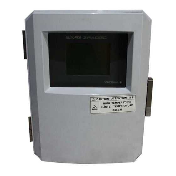
2.4 ZR402G Separate-type Converter 2.4.1 Standard Specification The ZR402G Separate-type Converter can be controlled by LCD touchscreen on the converter. Display: LCD display of size 320 by 240 dot with touchscreen. Output Signal: 4 to 20 mA DC, two points (maximum load resistance 550 ) Contact Output Signal: four points (one is fail-safe, normally open) Contact Input: two points Auto-calibration Output: Two points (for dedicated auto-calibration unit) -
Page 29: Functions
2. Specifications Finish: Polyurethane corrosion-resistance coating Weight: Approx. 6 kg 2.4.2 Functions Display Functions: Value Display; Displays values of the measured oxygen concentration, etc Graph Display; Displays trends of measured oxygen concentration Data Display; Displays various useful data for maintenance, such as cell temperature, reference junction temperature, maximum/minimum oxygen concentration, or the like Status Message;... - Page 30 Display and setting content: Measuring-related items: Oxygen concentration (vol% O ), Output current value (mA), air ratio, moisture quantity (in hot gases) (vol% H Display Items: Cell temperature ( C), thermocouple reference junction temperature ( C), maximum/minimum/average oxygen concentration (vol% O ), cell e.m.f.
- Page 31 2. Specifications (1) Abnormal, (2) High-high alarm, (3) High-alarm, (4) Low-low alarm, (5) Low-alarm, (6) Maintenance, (7) Calibration, (8) Range switching answer-back, (9) Warm-up, (10) Calibration-gas pressure decrease (answer-back of contact input), (11) Temperature high-alarm, (12) Blowback start, (13) Flameout gas detection (answerback of contact input) Contact Input: Two (points, voltage-free) contact in inputs The following functions are programmable for contact inputs:...
- Page 32 • External Dimensions 1 to 6 (Panel Thickness) 2-inch mounting pipe 6 holes EXA ZR402G for Wall mounting 57.3 136.3 54.7 8-G1/2, 8-1/2NPT etc (Wiring connection) (for wall mounting) 6 holes 38 24 14 38 4-R8 to R10 4-C5 to C8 Wall mounting Panel Cut-out 205.5...
-
Page 33: Za8F Flow Setting Unit And Zr40H Automatic Calibration Unit
Air Consumption: Approx. 1.5 l/min Weight: Approx. 2.3kg Calibration gas (zero gas, span gas) flow 0.7 l/m (at calibration time only) Note Use instrument air for span calibration gas, if no instrument air is available, contact YOKOGAWA. Model Suffix code Option code Description... - Page 34 • External Dimensions Unit: mm 6 hole REFERENCE CHECK REFERENCE SRAN ZERO Span gas inlet Reference air outlet Zero gas outlet Zero gas inlet 4-Rc1/4 Piping connection port Instrument air inlet CHECK Flow Flow meter meter AIR IN ZERO SPAN Instrument air GAS IN GAS IN...
-
Page 35: Zr40H Automatic Calibration Unit
2. Specifications 2.5.2 ZR40H Automatic Calibration Unit This automatic calibration unit is applied to supply specified flow of reference gas and calibration gas during automatic calibration to the detector in a system configuration (System 3). • Specifications Used when auto calibration is required for the separate type and instrument air is provided. - Page 36 • External Dimensions 2B pipe mounting example Unit : mm wiring inlet ; 2-G1/2,Pg13.5,M2031.5 or 1/2NPT(Female) (wiring inlet is at same position on rear) *1 with four M6 screws can wall-mount 116.5 71.5 41.2 41.2 Flowmeter Setting Valve for reference air Setting Valve for calibration gas calibration gas outlet...
- Page 37 2. Specifications • Piping Diagram CHECK flow flow meter meter AIR IN ZERO GAS IN Instrument air Approx. 1.5 l/min. F2.6-3E.EPS *2 Needle valve is supplied as accessory with flow meter. IM 11M12A01-02E 2-21...
-
Page 38: Zo21S Standard Gas Unit
2.6 ZO21S Standard Gas Unit This is a handy unit to supply zero gas and span gas to the detector in a system configu- ration based on System 1. It is used in combination with the detector only during calibration. Standard Specifications Function: Portable unit for calibration gas supply consisting of span gas (air) pump, zero gas cylinder with sealed inlet, flow rate checker and flow rate needle valve. - Page 39 2. Specifications • External Dimensions Unit : mm Flow checker Span gas valve Zero gas valve Gas outlet Zero gas cylinder (6 cylinder): E7050BA F2.7E.EPS IM 11M12A01-02E 2-23...
-
Page 40: Other Equipment
2.7 Other Equipment 2.7.1 Dust Filter for the Detector (Part No.: K9471UA) This filter is used to protect the detector sensor from a corrosive dust component or from a high concentration of dust when the oxygen concentration in utility boilers or concrete kilns are to be measured. -
Page 41: Auxiliary Ejector For High Temperature (Part No. E7046Ec Or E7046En)
2. Specifications 2.7.2 Auxiliary Ejector for High Temperature (Part No. E7046EC or E7046EN) This ejector is used where pressure of measured gas for high temperature detector is negative. This ejector consists of an ejector assembly, a pressure gauge and a needle valve. - Page 42 E7046EC ; Piping connections, Rc1/4( part) or Rc1/4( part ), E7046EN ; Piping connections,1/4NPT female ( part) or 1/4NTP male( part ) Pressure gauge 4 or 1/4 inch, conduit (stainless) Needle valve Approx.88 Ejector assembly PT 1/2 male Approx. Height when Detector lnstrument fully open...
-
Page 43: Stop Valve (Part No. L9852Cb Or G7016Xh)
2. Specifications < Pressure setting for the auxiliary ejector for high-temperature use > Pressure supply for the auxiliary ejector should be set so that the suction flow of the measured gas becomes approximately 5 l/min. To set this, proceed as follows: (1) In Graph 4, draw a horizontal line from the 5 l/min point. -
Page 44: Check Valve (Part No. K9292Dn Or K9292Ds)
2.7.4 Check Valve (Part No. K9292DN or K9292DS) This valve is mounted on the calibration gas line (directly connected to the detector). This is applied to a system based on the (System 2 and 3) system configuration . This valve prevents the process gas from entering the calibration gas line. Although it functions as a stop valve, operation is easier than a stop valve as it does not require opening/closing at each calibration. -
Page 45: Air Set (Part No. G7011Xf Or E7040El)
2. Specifications 2.7.5 Air Set (Part No. G7011XF or E7040EL) This set is used to lower the pressure when instrument air is used as the reference and span gases. Standard Specifications Primary Pressure: Max. 2 MPa G Secondary Pressure: 9.8 to 196 kPa G Connection: Rc1/4 or 1/4FNPT (includes joint adapter) Weight: Approx.1 kg Part No. -
Page 46: Cylinder Regulator Valve (Part No. G7013Xf Or G7014Xf)
2.7.7 Cylinder Regulator Valve (Part No. G7013XF or G7014XF) This regulator valve is used with the zero gas cylinders. Standard Specifications Pressure gauge: Primary 0 to 25 MPa G, Secondary 0 to 0.5 MPa G Connection: Inlet W22 14 threads, right hand screw Outlet Rc1/4 or 1/4FNPT Material: Brass body Secondary Primary... -
Page 47: Model Zr22A Heater Assembly
2. Specifications 2.7.9 Model ZR22A Heater Assembly Model Suffix code Option code Description Heater Assembly for ZR22G ZR22A 0.15 m -015 Length 0.4 m -040 ( 1) -070 0.7 m -100 1.5 m -150 -200 -250 2.5 m -300 with Jig JIg for change None Always -A... -
Page 49: Installation
3. Installation Installation This chapter describes installation of the following equipment: Ssction 3.1 Detector (except model ZR22G-015) Ssction 3.2 Detector (model ZR22G-015) Ssction 3.3 Converter Ssction 3.4 ZA8F Flow Setting Unit Ssction 3.5 ZR40H Automatic Calibration Unit Ssction 3.6 Calibration Gas Unit Case (E7044KF) 3.1 Installation of the Detector 3.1.1 Location... -
Page 50: Installation Of The Detector
(1) Do not mount the probe with the tip higher than the probe base. (2) If the probe length is 2.5 meters or more, the detector should be mounted vertically (no more than a 5 tilt). (3) The detector probe should be mounted at right angles to the measurement gas flow or the probe tip should point downstream. -
Page 51: Installation Of The Dust Filter( Part No K9471Ua)
3. Installation 3.1.4 Installation of the Dust Filter( Part No K9471UA) CAUTION • The dust filter is used to protect the Zirconia sensor from corrosive dust or a high concentration of dust such as in utility boilers and concrete kilns. If a filter is used in combustion systems other than these, it may have adverse effects such as response delay. - Page 52 <Detector with a probe protector (Model ZO21R-L- *B for enhance forth> The detector is used with a probe protector to support the probe (ZR22G) when the probe length is 2.5m or more and it is mounted horizontally. (1) Put a gasket (provided by the user) between the flanges, and mount the probe protector in the probe insertion hole.
-
Page 53: Installation Of The Detector (Model Zr22G-015)
3. Installation 3.2 Installation of the Detector (Model ZR22G-015) 3.2.1 Installation Location This model detector is used with the High-temperature Probe Adapter (Model ZO21P-H) when the temperature of sample gas exceeds 700 C, or when it is required due to maintenance spaces. - Page 54 <When the surface temperature is less than 200 C or the dew point of the measure- ment gas> (1) When the furnace pressure is negative, raise the analyzer pressure to increase induction flow of the measurement gas. Refer to Section 2.7.2, Auxiliary Ejector for High-temperature Use, for the setting of induction flow.
-
Page 55: Probe Insertion Hole
3. Installation 3.2.3 Probe Insertion Hole A high-temperature detector consists of a ZR22G-015 Detector and ZO21P High- temperature Probe Adapter. When forming the probe insertion hole, the following should be taken into consideration: (1) If the probe is made of silicon carbide (SiC), the probe hole should be formed so that the probe is mounted vertically (no more than a 5 tilt). - Page 56 A high-temperature detector should be mounted as follows: (1) It is recommended to mount the detector vertically. When it is impossible due to the physical arrangements and the detector is mounted horizontally, ensure that the probe tip be placed no higher than the probe base. (2) When mounting a high-temperature probe adapter, be sure to insert a gasket between the flanges to prevent gas leakage.
-
Page 57: Installation Of The Converter
3. Installation 3.3 Installation of the Converter 3.3.1 Location The following should be taken into consideration when installing the converter: (1) Readability of the indicated values of oxygen concentration or messages on the converter display. Easy and safe access to the converter for operating keys on the panel. (2) Easy and safe access to the converter for checking and maintenance work. - Page 58 <Wall Mounting> (1) Drill mounting holes through the wall as shown in Figure 3.8. Unit: mm Four holes 6 mm in diameter for M5 screws 126.5 F3.8E.EPS Figure 3.8 Mounting holes (2) Mount the converter. Secure the converter on the wall using four screws. Note: For wall mounting, the bracket and bolts are not used.
- Page 59 3. Installation <Panel Mounting> (1) Cut out the panel according to Figure 3.10. Unit: mm F3.10E.EPS Figure 3.10 Panel cutout sizes (2) Remove the fitting from the converter by loosening the four screws. (3) Insert the converter case into the cutout hole of the panel. (4) Attach the mounting fitting which is once removed in step (2) again to the converter.
-
Page 60: Installation Of Za8F Flow Setting Unit
3.4 Installation of ZA8F Flow Setting Unit 3.4.1 Location The following should be taken into consideration: (1) Easy access to the unit for checking and maintenance work. (2) Near to the detector and the converter (3) No corrosive gas. (4) An ambient temperature of not more than 55 C and little changes of temperature. (5) No vibration. - Page 61 3. Installation <Wall Mounting> (1) Make a hole in the wall as illustrated in Figure 3.13. Unit : mm 4 - 6.5 hole, or M6 screw F3.13E.EPS Figure 3.13 Mounting holes (2) Mount the flow setting unit. Remove the pipe mounting parts from the mount fittings of the flow setting unit and attach the unit securely on the wall with four screws.
-
Page 62: Installation Of Zr40H Automatic Calibration Unit
3.5 Installation of ZR40H Automatic Calibration Unit 3.5.1 Location The following should be taken into consideration: (1) Easy access to the unit for checking and maintenance work. (2) Near to the detector and the converter (3) No corrosive gas. (4) An ambient temperature of not more than 55 C and little change of temperature. (5) No vibration. - Page 63 3. Installation <Wall Mounting> (1) Make a hole in the wall as illustrated in Figure 3.16. Unit : mm 4 - 6.5 hole, or M6 screw F3.13E.EPS Figure 3.16 Mounting holes (2) Mount the Automatic Calibration Unit. Remove the pipe mounting parts from the mount fittings of the flow setting unit and attach the unit on the wall with four screws.
-
Page 64: Installation Of The Calibration Gas Unit Case (E7044Kf)
3.6 Installation of the Calibration Gas Unit Case (E7044KF) The calibration gas unit case is used to store the G7001ZC zero gas cylinders. 3.6.1 Location The following should be taken into consideration: (1) Easy access for cylinder replacement (2) Easy access for checking (3) Near to the detector and converter as well as the flow setting unit. -
Page 65: Insulation Resistance Test
3. Installation 3.7 Insulation Resistance Test Even if the testing voltage is not so great that it causes dielectric breakdown, testing may cause deterioration in insulation and a possible safety hazard. Therefore, conduct this test only when it is necessary. The applied voltage for this test shall be 500 V DC or less. -
Page 66: External Dimensions Of Detectors With Pressure Compensation
3.8 External Dimensions of Detectors with Pressure Com- pensation ZR22G- - -A-P Flange ; Equivalent to ANSI CLASS150-2-RF Unit: mm Rc1/4 or 1/4NPT Reference air inlet 156 3 2-G1/2, 2-1/2NPT etc. Cable connection port Reference gas outlet Rc1/4 or 1/4NPT PIPING Flange Flange... - Page 67 3. Installation ZR22G- - -B-P Flange ; Equivalent to ANSI CLASS150-3-RF Unit: mm Rc1/4 or 1/4NPT Reference air inlet 156 3 2-G1/2, 2-1/2NPT etc. Cable connection port Reference gas outlet Rc1/4 or 1/4NPT PIPING Flange Flange Calibration gas inlet Stop Valve PIPING : A Flange Weight...
- Page 68 ZR22G- - -E-P Flange ; Equivalent to DIN PN10-DN50-A Rc1/4 or 1/4NPT Unit: mm Reference air inlet 156 3 2-G1/2, 2-1/2NPT etc. Cable connection port Reference gas outlet Rc1/4 or 1/4NPT PIPING Flange Flange Calibration gas inlet Stop Valve PIPING : A Flange Weight Model, Code...
- Page 69 3. Installation ZR22G- - -G-P Flange ; Equivalent to DIN PN10-DN100-A Unit: mm Rc1/4 or 1/4NPT Reference air inlet 156 3 2-G1/2, 2-1/2NPT etc. Cable connection port Reference gas outlet Rc1/4 or 1/4NPT PIPING Flange Flange Calibration gas inlet Stop Valve PIPING : A Flange Weight...
- Page 70 ZR22G- - -L-P Flange ; Equivalent to JIS 10K-65-FF Unit: mm Rc1/4 or 1/4NPT Reference air inlet 156 3 2-G1/2, 2-1/2NPT etc. Cable connection port Reference gas outlet Rc1/4 or 1/4NPT PIPING Flange Flange Calibration gas inlet Stop Valve PIPING : A Flange Weight Model, Code...
- Page 71 3. Installation ZR22G- - -P-P Flange ; Equivalent to JIS 10K-100-FF Unit: mm Rc1/4 or 1/4NPT Reference air inlet 156 3 2-G1/2, 2-1/2NPT etc. Cable connection port Reference gas outlet Rc1/4 or 1/4NPT PIPING Flange Flange Calibration gas inlet Stop Valve PIPING : A Flange Weight...
- Page 72 ZR22G- - -S-P Flange ; Equivalent to JPI CLASS150-3-RF Unit: mm Rc1/4 or 1/4NPT Reference air inlet 156 3 2-G1/2, 2-1/2NPT etc. Cable connection port Reference gas outlet Rc1/4 or 1/4NPT PIPING Flange Flange Calibration gas inlet Stop Valve PIPING : A Flange Weight Model, Code...
-
Page 73: Piping
4. Piping Piping This chapter describes piping procedures based on three typical system configurations for EXAxt ZR Separate-type Zirconia Oxygen Analyzer. • Ensure that each check valve, stop valve and joint used for piping does not allow leakage. Especially, if there is any leakage of the calibration gas from piping and joints , it may cause clogging of the piping or incorrect calibration. -
Page 74: Parts Required For Piping In System 1
Table 4.1 Detector Piping location Parts Note General-use Calibration gas inlet Stop valve of a quality specified by YOKOGAWA detector (L9852CB or G7016XH) nipple * Rc1/4 or 1/4 NPT general parts joint for tube connection Rc1/4 (1/4NPT) for a 6... -
Page 75: Connection To The Calibration Gas Inlet
First, mount a stop valve (of a quality specified by YOKOGAWA) on a nipple (found on the open market) as illustrated in Figure 4.2, and mount a joint (also found on the open market) at the stop valve tip. -
Page 76: Piping To The High-Temperature Probe Adapter
4.1.4 Piping to the High-temperature Probe Adapter • The measured gas should be at a temperature below 700 C before reaching the detector sensor. If the gas is under negative pressure, it should be fed to the detector by suction. •... - Page 77 4. Piping In cases where condensation is likely to occur in the probe adapter when the sample gas is cooled, protect the probe adapter with an insulating material as illustrated in Figure 4.5. Cover flange Sample gas outlet Adapter for high temperature probe Detector Insulating material Probe...
-
Page 78: Piping For System 2
4.2 Piping for System 2 Piping in System 2 is illustrated in Figure 4.7. Model ZR22G Separate type Zirconia Oxygen Model ZR402G Converter Analyzer, Detector EXA ZR402G Signal (6-core shield cable) Stop valve 100 to or Check valve 240 V AC Heater (2-core) Contact input Model ZA8F flow setting unit... -
Page 79: Piping Parts For System 2
Table 4.2 Detector Piping location Parts Note General-use Calibration gas inlet Stop valve or check valve Recomended by YOKOGAWA (L9852CB or detector G7016XH) Provided by YOKOGAWA (K9292DN or K9292DS) Nipple * Rc1/4 or 1/4 NPT general parts Zero gas cylinder User«s scope... -
Page 80: Piping For The Calibration Gas
Mount a regulator valve (specified by YOKOGAWA) on the cylinder. Mount a check valve or stop valve (specified by YOKOGAWA) on the nipple (found on the open market) at the calibration gas inlet of the detector as illustrated in Figure 4.8. -
Page 81: Piping For System 3
4. Piping 4.3 Piping for System 3 Piping in System 3 is illustrated in Figure 4.10. In System 3, calibration is automated; however, the piping is basically the same as that of System 2. Refer to Section 4.2. Adjust secondary pressure of both the air set and the zero gas reducing valve so that these two pressures are approximately the same. -
Page 82: Blow Back Piping
Model ZR22G Separate type Zirconia Oxygen Model ZR402G Converter Analyzer, Detector EXA ZR402G Signal (6-core shield cable) Check valve 100 to 240 V AC Contact input Heater (2-core cable) Analog output, contact output Digital output (HART) Needle flowmeter valve Reference gas Air Set Calibration gas Instrument air... - Page 83 • Two-way solenoid valve: “ Open “ when electric current is on. (Found on the open market) • Air set (recommended by YOKOGAWA, G7011XF or E7040EL) <Blow pipe manufacturing> Manufacture the blow pipe as illustrated in Figure 4.12, and mount it on the high- temperature probe adapter.
-
Page 84: Piping For The Detector With Pressure Compensation
4.4 Piping for the Detector with Pressure Compensation ZR22G- - - -P Detector with Pressure Compensation may be used in System 2 and System 3. However, it cannot use piping for high-temperature probe adapter or blow back piping. Use this style detector whenever the furnace pressure exceeds 5 kPa (see Note). - Page 85 4. Piping CAUTION • Use suitable cable glands to completely seal the detector. As far as possible do not stop the instrument air flow, to prevent the measured gas from entering the detector and damaging the zirconia cell. • Connect the stop valve, which is at the calibration gas inlet, directly to the detector. If there is piping between the detector and the valve, condensation may damage the sensor by rapid cooling when calibration gas is introduced.
-
Page 86: Piping Parts For A System Using Detector With Pressure Compensation4-14
Nipple * Rc1/4 or 1/4 NPT general parts Zero gas cylinder User«s scope Gas pressure regulator of a quality specified by YOKOGAWA (G7013XF or G7014XF) Joint for tube connection Rc1/4 or 1/4 NPT general parts Reference gas inlet Air set... -
Page 87: Wiring
5. Wiring Wiring In this Chapter, the wiring necessary for connection to the EXAxtZR Separate-type Zirconia Oxygen Analyzer is described. 5.1 General CAUTION • NEVER supply current to the converter or any other device constituting a power circuit in combination with the converter, until all wiring is completed. -
Page 88: Terminals For The External Wiring In The Converter
CAUTION • Select suitable cable O.D. to match the cable gland size. • Protective grounding should be connected in ways equivalent to JIS D style (Class 3) grounding (the grounding resistance is 100 or less). • Special consideration of cable length should be taken for the HART communication, For the detail, refer to Section 1.1.2 of the IM 11M12A01-51E "... -
Page 89: Wiring
5. Wiring 5.1.2 Wiring Connect the following wiring to the converter. It requires a maximum of eight wiring connections as shown below. (1) Detector output (connects the converter with the detector.) (2) Detector heater power (connects the converter with the detector.) (3) Analog output signal (4) Power and ground (5) Contact output... -
Page 90: Mounting Of Cable Gland
5.1.3 Mounting of Cable Gland For each cable connection opening of the converter, mount a conduit that matches the thread size, or a cable gland. EXA ZR402G 8-G1/2, 8-1/2NPT or the like (Wiring connection) Ground terminal (M4) Adaptor for 1/2 NPT thread F5.4E.EPS Figure 5.4 Cable gland mounting IM 11M12A01-02E... -
Page 91: Wiring For Detector Output
5. Wiring 5.2 Wiring for Detector Output This wiring enables the converter to receive cell output from the detector, output from a thermocouple and a reference junction compensation signal. Install wires that allow for 10 of loop resistance or less. Keep detector wiring away from power wiring. Separate signal and power wiring. -
Page 92: Connection To The Detector
5.2.2 Connection to the Detector To connect cables to the detector, proceed as follows: (1) Mount conduits of the specified thread size or cable glands to the wiring connections of the detector. The detector may need to be removed in future for maintenance, so be sure to allow sufficient cable length. -
Page 93: Connection To The Converter
5. Wiring 5.2.3 Connection to the Converter To connect the wiring to the converter, proceed as follows: (1) M4 screws are used for the terminals of the converter. Each wire in the cable should be terminated in the corresponding size crimp-on terminal. (2) When a rubber insulated glass braided wire is used for wiring to the detector, use a terminal box. -
Page 94: Wiring For Power To Detector Heater
5.3 Wiring for Power to Detector Heater This wiring provides electric power from the converter to the heater for heating the sensor in the detector. (1) Ambient temperature of the detector: 80 C or less Detector Converter HTR 7 HEATER HTR 8 (2) Ambient temperature of the detector: exceeding 80 C Terminal box... -
Page 95: Connection To Converter
5. Wiring CAUTION •Before opening the detector cover, loosen the lock screw. If the screw is not loosened first, the screw will damage the cover, and the terminal box will require replacement. When opening and closing the cover, remove any sand particles or dust to avoid gouging the thread. -
Page 96: Wiring For Analog Output
5.4 Wiring for Analog Output This wiring is for transmitting 4 to 20 mA DC output signals to a device, e.g. recorder. Maintain the load resistance including the wiring resistance at 550 or less. Converter Receiver 1 AO1(+) AO1(-) AO2(+) AO2(-) Receiver 2 Shielded cable... -
Page 97: Power And Grounding Wiring
5. Wiring 5.5 Power and Grounding Wiring This wiring supplies power to the converter and grounds the converter/detector. Converter Detector L N G Grounding to the ground terminal on the converter case Converter case Ground Jumper plate Crimp-on terminal of the ground wire 100 - 240VAC Lock washer... -
Page 98: Contact Output Wiring
5.6 Contact Output Wiring The converter can output a maximum of four contact signals. You can use these contact outputs after you select the type of outputs(e.g., “ low-limit alarm “ or “ high-limit alarm “) from the different output functions. When using these contact outputs, install the wiring as follows: Converter Terminal box... -
Page 99: Wiring For Zr40H Automatic Calibration Unit
5. Wiring 5.7 Wiring for ZR40H Automatic Calibration Unit This wiring is for operating the solenoid valve for the zero gas and the span gas in the ZR40H Automatic Calibration Unit, in a system where the calibration gas flow rate is automatically controlled (e.g. -
Page 100: Wiring Procedure
5.7.2 Wiring Procedure M4 screws are used for the terminals of the converter. Each cable should be terminated in the corresponding crimp-on terminals. M4 screws are used for the terminals of the solenoid valve as well. ZR40H Automatic Converter Calibration unit AC-Z Zero AC-S... -
Page 101: Contact Input Wiring
5. Wiring 5.8 Contact Input Wiring The converter can execute specified function when receiving contact signals. To use these contact signals, wire as follows: Converter Terminal box DI-1 Contact input 1 DI-2 DI-C Contact input 2 F5.14E.EPS Figure 5.14 Contact Input Wiring 5.8.1 Cable Specifications Use 2-core or 3-core cable for this wiring. -
Page 103: Components
6. Components Components In this Chapter, the names and functions of components are described for the major equipment of the EXAxt ZR Separate-type Zirconia Oxygen Analyzer. 6.1 ZR22G Detector 6.1.1 General-purpose Detector (except for Model ZR22G-015) Terminal box, NEMA 4X/IP66 equivalent (recirculation to furnace with pressure compensation only) Flange used to mount the detector. -
Page 104: High-Temperature Detector (Model Zr22G-015)
6.1.2 High-Temperature Detector (Model ZR22G-015) Sample gas outlet When a negative measurement gas pressure is used, connect the auxiliary ejector assembly. When the measurement gas is high-temperature and high-pressure, Separate type and does not fall below 700 C, High-temperature Detector connect a pressure control valve (ZR22G-015) (e.g. -
Page 105: Zr402G Converter
6. Components 6.2 ZR402G Converter Complete Operation Display Typical Converter Displays Interactive operations along with operation display Example of basic display A variety of display modes enabling you to select the operation mode freely Back-lit LCD display allows viewing even in areas of low lighting Error codes and details of errors are displayed no need to refer to instruction manual... -
Page 106: Za8F Flow Setting Unit, Zr40H Automatic Calibration Unit
6.3 ZA8F Flow Setting Unit, ZR40H Automatic Calibra- tion Unit Reference gas flow setting valve Span gas flow setting valve Zero gas flow setting valve Flow meter for reference gas Flow meter for calibration gas F6.4E.EPS Figure 6.4 ZA8F Flow Setting Unit Flowmeter for Calibration gas Flowmeter for... -
Page 107: Startup
7. Startup Startup The following describes the minimum operating requirements — from supplying power to the converter to analog output confirmation to manual calibration. System tuning by the HART communicator, refer to IM11M12A01-51E " HART Communication Protocol ". 7.1 Checking Piping and Wiring Connections Check that the piping and wiring connections have been properly completed in accor- dance with Chapter 4, “Piping,”... -
Page 108: Supplying Power To The Converter
7.3 Supplying Power to the Converter CAUTION To avoid temperature changes around the sensor, it is recommended that (rather than turning it on and off) power be continuously supplied to the Oxygen Analyzer if it is used in an application where it is used periodically. It is also recommended to flow a span gas (instrument air) beforehand. -
Page 109: Touchpanel Switch Operations
7. Startup 7.4 Touchpanel Switch Operations 7.4.1 Basic Panel and Switch The converter uses a touchpanel switch which can be operated by just touching the panel display. Figure 7.3 shows the basic panel display. The switches that appear in the switch display area vary depending on the panel display, allowing all switch operations. -
Page 110: Display Configuration (For Oxygen Analyzer)
7.4.2 Display Configuration (for Oxygen Analyzer) Figure 7.3.1 shows the configuration. A password the displays positioned below enables display Execution/Setup to be protected. If a password has not been set, press the [Enter] key to proceed to the next panel display. The Home key enables you to return to Execution/Setup from any panel display. -
Page 111: Display Functions
7. Startup 7.4.3 Display Functions Individual panel displays in the display configuration provide the following functions: (1) Basic panel display: Displays the values measured in three selected items (see Section 7.9, “Setting Display Items”). (2) Execution/Setup display: Selects the calibration, maintenance and setup items. (3) Detailed-data display: This allows you to view such detailed data as the cell electro- motive force and cell temperature (see Section 10.1.1, “Detailed-data Display,”... - Page 112 Operation Display Press the [ABC] key once. Press and hold the [ABC] key. Release the [ABC] key when the character B appears in the cursor position. Enter the character C in the same manner as above. Press the [other] key. Press and hold the [$%&] key and enter “%.”...
-
Page 113: Confirmation Of Converter Type Setting
7. Startup 7.5 Confirmation of Converter Type Setting This converter can be used for both the Oxygen Analyzer and the Humidity Analyzer. Before setting the operating data, be sure to check that the desired converter model has been set. Note that if the converter type setting is changed, the operating data that have been set are then initialized and the default settings remain. -
Page 114: Confirmation Of Detector Type Setting
7.6 Confirmation of Detector Type Setting Check that the detector in Figure 7.7 is the one for this equipment. WARNING • If this converter is to be used in conjunction with the ZO21D, the power requirements are limited to 125 V AC or less, 50 Hz or 60 Hz (it cannot be used with a 125 V or greater, or in the EEC). -
Page 115: Setting Display Item
7. Startup 7.9 Setting Display Item This section briefly describes the display item settings shown in Figure 7.11, “Basic Panel Display.” Tag name Tag: 21.0 Primary value Secondary value 17.43mA -Output1 17.43mA -Output2 Tertiary value F7.11E.EPS Figure 7.11 Basic Panel Display (1) Press the Setup key in the basic panel display to display the Execution/Setup display. - Page 116 Table 7.2 Display Items Secondary and Item Primary value Display tertiary values Oxygen concentration Oxygen concentration during measurement Air ratio Current computed air ratio Moisture quantity Moisture quantity (%H O) in the exhaust gas Output 1 item Oxygen concentration with the equipment set for oxygen analyzer (See *1 below.) Output 2 item Oxygen concentration with the equipment set for oxygen analyzer (See *1 below.) Current output 1...
-
Page 117: Checking Current Loop
7. Startup 7.10 Checking Current Loop The set current can be output as an analog output. (1) Press the Setup key on the basic panel display to display the Execution/Setup display. Then select Maintenance in the Execution/Setup display. (2) Select “mA-output loop check” in the Maintenance panel display to display the “mA- output loop check”... -
Page 118: Checking Contact I/O
7.11 Checking Contact I/O Conduct the contact input and output checking as well as operational checking of the solenoid valves for automatic calibration. 7.11.1 Checking Contact Output To check the contact output, follow these steps: (1) Press the Setup key in the basic panel display to display the Execution/Setup display. Select Maintenance in that display. -
Page 119: Checking Calibration Contact Output
7. Startup 7.11.2 Checking Calibration Contact Output The calibration contacts are used for solenoid valve drive signals for the ZR40H Automatic Calibration Unit. When using the ZR40H Automatic Calibration Unit, use the calibration contact output to check that the wiring connections have been properly completed and check equipment operation. -
Page 120: Calibration
7.12 Calibration The converter is calibrated in such a way that the actual zero and span gases are mea- sured and those measured values are used to agree with the oxygen concentrations in the respective gases. There are three types of calibration procedures available: (1) Manual calibration conducting zero and span calibrations, or either of these calibra- tions in turn. -
Page 121: Manual Calibration
7. Startup (2) Span-gas concentration With “Span gas conc” selected in the Calibration setup display, display the Numeric- data Entry display and enter an oxygen concentration value for the span-gas calibra- tion; If instrument air is used, enter 02100 for a 21 vol% O value. - Page 122 (3) Follow the display message in Figure 7.19 to turn on span gas flow. Open the span- gas flow valve for the Flow Setting Unit by loosening the valve lock-nut and slowly turning the valve shaft counterclockwise to flow the span gas at 600 ml/min. ± 60 ml/min.
- Page 123 7. Startup (7) Follow the instructions in the display as in Figure 7.23 to turn on the zero gas flow. To do this, open the zero-gas flow valve for the Flow Setting Unit and adjust that valve to obtain a flow of 600 ml/min. ± 60 ml/min. (The valve should be adjusted by loosening its lock nut and slowly turning the valve shaft counterclockwise.
- Page 124 (10) Select End in the display as shown in Figure 7.26. An oxygen concentration trend graph (with the oxygen concentration being measured) appears and HOLD TIME then flashes. This time is referred to as the output-stabilization time. If the HOLD TIME has been set with the output-hold setting, the analog output remains held (refer to Section 8.2, “Setting Output Hold,”...
-
Page 125: Detailed Data Setting
8. Detailed Data Setting Detailed Data Setting 8.1 Current Output Setting This section describes setting of the analog output range. 8.1.1 Setting Minimum Current (4 mA) and Maximum Current (20 mA) To set the minimum and maximum currents, proceed as follows: (1) Select Setup in the Execution/Setup display. -
Page 126: Entering Output Damping Constants
Setting example 2 If the setting (for a 4 mA current) is 75% O , you must set the oxygen concentration for the maximum (20 mA) point at more than 98% O 1.3). (Numbers after the decimal point are rounded up.) Ranges over which oxygen concentrations can be set Outside ranges... -
Page 127: Default Values
8. Detailed Data Setting 8.1.5 Default Values When the analyzer is delivered or reset to defaults, the output current default settings by as shown in Table 8.1.1. Table 8.1.1 Output Current Default Values Item Default setting Min. oxygen concentration 0% O Max. -
Page 128: Output Hold Setting
8.2 Output Hold Setting The “output hold” functions hold an analog output signal at a preset value during the equipment’s warm-up time or calibration or if an error arises. Outputs 1 and 2 can be set individually. Table 8.1.2 shows the analog outputs that can be retained and the indi- vidual states. -
Page 129: Preference Order Of Output Hold Value
8. Detailed Data Setting For semi-automatic calibration, “under calibration” is the time required from entering calibration instructions to perform a, either by using the touchpanel or by a contact input, calibration until the output stabilization time elapses. For automatic calibration, “under calibration” is the time required, after performing an appropriate calibration until the output stabilization time elapses. -
Page 130: Output Hold Setting
8.2.3 Output Hold Setting To set the output hold, follow these steps: (1) Press the Setup key in the basic panel display to display the Execution/Setup display. Then select Setup in the Execution/Setup display. Next, select the mA-output setup and then the mA-output preset display as shown in Figure 8.2. mA-outputs presets mA-outputs presets Warm up:... -
Page 131: Setting Oxygen Concentration Alarms
8. Detailed Data Setting 8.3 Setting Oxygen Concentration Alarms The analyzer enables the setting of four alarms — high-high, high, low, and low-low alarms — depending upon the oxygen concentration. The following section sets out the alarm operations and setting procedures. 8.3.1 Alarm Values (1) High-high and high alarm values... -
Page 132: Alarm Setting Procedure
In the example in Figure 8.4, the high-limit alarm point is set to 7.5% O , the delay time is set to five seconds, and hysteresis is set to 2% O Alarm output actions in this figure are as follows: (1) In “A”... -
Page 133: Default Values
8. Detailed Data Setting Oxygen alarms Alarms setup High High alarm: OFF Parameter: Oxygen Set value: 1 0 0 . 0 % O2 Hysteresis: 0.1%O2 High alarm: Contact delay: Set value: 1 0 0 . 0 % O2 Low alarm: Setpoints Set value: 0 . -
Page 134: Output Contact Setup
8.4 Output Contact Setup 8.4.1 Output Contact Mechanical relays provide contact outputs. Be sure to observe relay contact ratings. (For details, consult the specifications requirements.) The operation modes of each contact output are as follows. For output contacts 1 to 3 you can select open or closed contact when the contact is “operated”. - Page 135 8. Detailed Data Setting Output contact 1 Contact setup Output contact 1 Alarms Others Output contact 2 During power-off the Output contact 3 contact is open and Output contact 4 in condition it is Open lnput contacts Enter Enter F8.7E.EPS F8.8E.EPS Figure 8.7 Contact Setup Display Figure 8.8 Output Contact 1 Display...
- Page 136 Table 8.5 Output Contact Settings Item to be selected Brief description High-high- If "high-high alarm ON" is selected, contact output occurs when the high-high-limit limit alarm alarm is issued. To do this, it is required, in alarm setup, that the high-high alarm be set on beforehand (see Section 8.3).
-
Page 137: Default Values
8. Detailed Data Setting 8.4.3 Default Values When the analyzer is delivered, or if data are initialized, alarm and other setting defaults are as shown in Table 8.6. Table 8.6 Output Contact Default Settings Item Output Output Output Output contact 1 contact 2 contact 3 contact 4 High-high-... -
Page 138: Input Contact Settings
8.5 Input Contact Settings 8.5.1 Input Contact Functions The converter input contacts execute set functions by accepting a remote dry-contact (“voltage-free contact”) signal. Table 8.7 shows the functions executed by a remote contact signal. Table 8.7 Input Contact Functions Item Function Calibration-gas pressure While the contact signal is on, neither semi-automatic nor... -
Page 139: Setting Procedure
8. Detailed Data Setting 8.5.2 Setting Procedure The following are set so that semi-automatic calibration starts when input contact open is applied to “Input1.” Proceed as follows: (1) Press the Setup key in the Basic panel display to display the Execution/Setup display. (2) Select Setup in the Execution/Setup display to display the “Commissioning”... -
Page 140: Other Settings
8.6 Other Settings 8.6.1 Setting the Date-and-Time The following describe how to set the date-and-time. Automatic calibration or blowback works following this setting. Proceed as follows: (1) Press the Setup key in the Basic panel display to display the Execution/Setup display. -
Page 141: Setting Fuels
8. Detailed Data Setting 8.6.2.2 Default Values When the analyzer is delivered, or if data are initialized, the average-value calculation periods and maximum- and minimum-value monitoring periods are by default one hour and 24 hours respectively. Averaging Set period over which average is calculated: Set period over which maximum and minimum is... - Page 142 Fill in the boxes with fuel parameters in Equation 2 above to calculate the moisture content. Use A0, Gw and X shown in Table 8.8. If there are no appropriate fuel data in Table 8.8, use the following equations for calculation. Find the value of “Z” in Equa- tions 1 and 2 using Japanese Standard JIS B 8222.
- Page 143 8. Detailed Data Setting 0.046 0.044 0.042 0.040 0.038 0.036 0.034 0.032 0.030 0.028 Wet-bulb 0.026 Absolute temperature, C humidity, kg/kg 0.024 0.022 0.020 0.018 0.016 0.014 0.012 0.010 0.008 0.006 0.004 0.002 0.000 12 14 16 18 20 22 24 26 28 30 32 34 36 38 40 Dry-bulb temperature, C F8.17E.EPS...
- Page 144 Table 8.8 Fuel Data For liquid fuel Fuel Chemical component Theoretical Amount of combustion gas Calorific power Specific amount of properties (weight percentage) kJ/kg weight air for value combustion kg/l Type Higher Lower O SO Total content order order 0.78~ Kerosene 85.7 14.0...
- Page 145 8. Detailed Data Setting 8.6.3.2 Procedure To make a fuel setting, follow these steps: (1) Press the Setup key in the basic panel display to display the Execution/Setup display. (2) Select Setup in the Execution/Setup display. The “Commissioning” (Setup) display then appears.
-
Page 146: Setting Passwords
8.6.4 Setting Passwords The converter enables password settings to prevent unauthorized switching from the Execution/Setup menu lower level menu displays. Set passwords for calibration, blowback and maintenance use and for setup use individually. Proceed as follows: (1) Press the Setup key in the basic panel display to display the Execution/Setup display. (2) Choose Setup to display the “Commissioning”... -
Page 147: Calibration
9. Calibration Calibration 9.1 Calibration Briefs 9.1.1 Principle of Measurement This section sets forth the principles of measurement with a zirconia oxygen analyzer before detailing calibration. A solid electrolyte such as zirconia allows the conductivity of oxygen ions at high temperatures. -
Page 148: Calibration Gas
0.51% 0 ,81.92mV(Zero origin of calibration) Cell voltage (mV) 21.0% O , 0mV (Span origin of calibration) 21.0 Oxygen concentration (vol %) F9.1E.EPS Figure 9.1 Oxygen concentration in a Measurement Gas vs Cell Voltage (21% O Equivalent) The measurement principles of a zirconia oxygen analyzer have been described above. However, the relationship between oxygen concentration and the electromotive force of a cell is only theoretical. -
Page 149: Compensation
9. Calibration 9.1.3 Compensation The deviation of a measured value from the theoretical cell electromotive force is checked by the method in Figure 9.2 or 9.3. Figure 9.2 shows a two-point calibration using two gases: zero and span. Cell electromo- tive forces for a span gas with an oxygen concentration p1 and a zero gas with an oxygen concentration p2 are measured while determining the calibration curve passing between these two points. -
Page 150: Characteristic Data From A Sensor Measured During Calibration
81.92 Zero origin Cell electromotive Calibration curve before Previous force, mV correction zero-gas data Corrected calibration curve (theoretical calibration curve) Span origin 21.0 0.51 Span-gas concentration Oxygen concentration (percent oxygen by volume) Zero-point correction factor = (B/A) x 100 (percent) Correctable range: 100 ± 30 percent Correctable range: 0 ±... -
Page 151: Calibration Procedures
9. Calibration 9.2 Calibration Procedures CAUTION Calibration should be made under normal operating conditions (if the probe is connected to a furnace, the analyzer will undergo calibration under the operating conditions of the furnace). To make a precise calibration, conduct both zero-point and span calibrations. 9.2.1 Calibration Setting The following sets forth the required calibration settings:... - Page 152 9.2.1.2 Calibration Procedure Select both span and zero calibrations or span calibration only or zero calibration only. Usually select span and zero calibrations. Select Points from the Calibration setup display and then you can select “Both,” “Span” or “Zero” (see Figure 9.5 below). Calibration setup Calibration setup Mode:...
- Page 153 9. Calibration 9.2.1.5 Setting Calibration Time • When the calibration mode is in manual: First set the output stabilization time. This indicates the time required from the end of calibration to entering a measurement again. This time, after calibration, the measure- ment gas enters the sensor to set the time until the output returns to normal.
-
Page 154: Default Values
(1) Select the “Calibration timing” display. A panel display as shown in Figure 9.7 appears. (2) Select each item for the calibration to display the numeric-data entry display. Enter the desired numeric values for the calibration. Calibration timing Hold time: 1 0 min 0 0 s Csl time: 1 0 min 0 0 s lnterval:... -
Page 155: Calibration
9. Calibration 9.2.3 Calibration 9.2.3.1 Manual Calibration For manual calibration, consult Section 7.12, “Calibration,” earlier in this manual. 9.2.3.2 Semi-automatic Calibration To start calibration, follow these steps: (1) Press the Setup key in the basic panel display to display the Execution/Setup display. Then select Calibration from the Execution/Setup display. - Page 156 9.2.3.3 Automatic Calibration No execution operations are required for automatic calibration. Automatic calibration starts in accordance with a preset start day and time. Calibration is then executed at preset intervals. CAUTION Before conducting a semi-automatic or automatic calibration, run the automatic calibra- tion unit beforehand to obtain a calibration flow of 600 ml/min.
-
Page 157: Other Functions
10. Other Functions 10. Other Functions 10.1 Display 10.1.1 Detailed Display Press the Detailed-data key on the basic panel display to display the detailed operation data as shown in Figure 10.1. Pressing the key, you can advance the page or go back to your desired page. •... - Page 158 10.1.1.2 Response Time The cell’s response time is obtained in the procedure shown in Figure 10.3. If only either a zero-point or span calibration has been carried out, the response time will not be measured just as it will not be measured in manual calibration. Five minutes maximum Response time 100%...
- Page 159 10. Other Functions 10.1.1.6 Cell Voltage The cell (sensor) voltage will be an index to determine the amount of degradation of the sensor. The cell voltage corresponds to the oxygen concentration currently being measured. If the indicated voltage approximates the ideal value (corresponding to the measured oxygen concentration), the sensor will be assumed to be normal.
- Page 160 10.1.1.11 Maximum Oxygen Concentration The maximum oxygen concentration and the time of its occurrence during the period specified in the Averaging display are displayed. If the setup period elapses, the maxi- mum oxygen concentration that has been displayed so far will be cleared and a new maximum oxygen concentration will be displayed.
-
Page 161: Trend Graph
10. Other Functions 10.1.2 Trend Graph Press the Graph display key in the basic panel display to switch to the graph display. This will help grasp the measured-value trend. Touching anywhere on the graph display will return to the basic panel display. To set the trend graph display, follow the steps in Section 10.1.2.1. - Page 162 25.0%O 10min./div Upper limit set Time per graduation, calculated by the set sampling period Lower limit set 0.0%O 12.3%O Currently measured value 60 data items Sampling period F10.5E.EPS Figure 10.5 Plotting Graph for Sampling Period 10.1.2.3 Setting Upper and Lower Limit Values on Graph Set upper- and lower-limit values on the graph in the following procedure: Press Upper limit in the Trend graph display.
-
Page 163: Auto(Matic) Revert Time
10. Other Functions 10.1.3 Auto(matic) Revert Time While the Execution/Setup display, or any other display that is positioned lower than the Execution/Setup display (see Figure 7.3.1, earlier in this manual), is displayed, if there is no key entry from the touchpanel for a certain time, the current display will automati- cally return to the basic panel display. -
Page 164: Blowback
Display setup Display item Trend graph Auto return time: 0 min Language: English Deutsch Francias Enter F10.7E.EPS Figure 10.7 Display Setup Display 10.2 Blowback 10.2.1 Blowback Setup The following sections describe the blowback setup procedures required for carrying out blowback. 10.2.1.1 Mode There are three blowback modes available: (1) No function –... - Page 165 10. Other Functions 10.2.1.2 Operation of Blowback Figure 10.9 shows a timing chart for the operation of blowback. To execute blowback with a contact input, use a contact input with an ON-time period of one to 11 seconds. Once blowback starts, a contact output opens and closes at ten-second intervals during the preset blowback time.
- Page 166 Blow back setup Mode: Auto Hold time: 1 0 min 0 0 s Blow back time: 1 0 min 0 0 s Interval: 3 0 d 0 0 h Start date: 0 1 / 0 1 / 0 0 Start tine: 0 0 : 0 0 Enter F10.10E.EPS...
-
Page 167: Operational Data Initialization
10. Other Functions 10.3 Operational Data Initialization Individual set data initialization enables you to return to the default values set at the time of delivery. There are two types of initializations: an all set-data initialization and a function-by-function initialization. Table 10.5 lists the initialization items and default values. - Page 168 Table 10.5 Initialization Items and Default Values Item Data to be initialized Default setting Type of equipment Not initialized Equipment Detector ZR22 selection Measurement gas Wet gas Display item 1st display item Oxygen concentration 2nd display item Current output 1 3rd display item Current output 2 Tag name...
- Page 169 10. Other Functions Item Data to be initialized Default setting Parameter Oxygen Alarm setting concentration Hysteresis 0.1%O Delayed action of alarm contact 3 seconds Alarm data High-high alarm None Alarm value 100%O Alarm set value High-limit alarm None Alarm value 100%O Low-limit alarm None...
-
Page 170: Reset
10.4 Reset Resetting enables the equipment to restart. If the equipment is reset, the power is turned off and then back on. In practical use, the power remains on, and the equipment is restarted under program control. Resetting will be possible in the following conditions: (1) Error 1 –... -
Page 171: Handling Of The Zo21S Standard Gas Unit
10. Other Functions 10.5 Handling of the ZO21S Standard Gas Unit The following describe how to flow zero and span gases using the ZO21S Standard Gas Unit. Operate the ZO21S Standard Gas Unit, for calibrating a system classified as System 1, according to the procedures that follow. 10.5.1 Standard Gas Unit Component Identification Carrying case Flow checker... -
Page 172: Installing Gas Cylinders
10.5.2 Installing Gas Cylinders Each ZO21S Standard Gas Unit comes with six zero-gas cylinders including a spare. Each gas cylinder contains 7-liters of gas with a 0.95 to 1.0 vol% O (concentration varies with each cylinder) and nitrogen, at a pressure of 700 kgPaG (at 35 C). The operating details and handling precautions are also printed on the product. - Page 173 10. Other Functions <Flow of span gas (air)> The standard gas unit is used only when manual calibration is employed. Therefore, the timing for flowing span gas (air) is included in the manual calibration flowchart de- scribed in Section 10.5.2. For operation of the converter, see Section 7.12, earlier in this manual.
- Page 174 (1) Use the needle of the zero gas valve “ CHECK GAS “ to puncture a hole in the gas cylinder installed as described in Section 10.5.2. Fully clockwise turn the valve regulator by hand. (2) Next, adjust the flow rate to 600 ml/min ± 60 ml/min (the flow check ball stops floating on the green line when the valve is slowly opened).
-
Page 175: Methods Of Operating Valves In The Za8F Flow Setting Unit
10. Other Functions 10.6 Methods of Operating Valves in the ZA8F Flow Setting Unit The ZA8F Flow Setting Unit is used as a calibration device for a system conforming to System 2. Calibration in such a system is to be manually operated. So, you have to operate the valve of the Flow Setting each time calibration is made (starting and stop- ping the calibration gas flow and adjusting the flow rate). -
Page 176: Operating The Zero Gas Flow Setting Valve
10.6.3 Operating the Zero Gas Flow Setting Valve Operate the zero gas flow setting valve during zero-point calibration in the following procedures: (1) When the display shown in Figure 10.17 appears during calibration, open the zero gas flow setting valve of the flow setting unit and adjust the flowrate to 600 ml/min ±... -
Page 177: Inspection And Maintenance
Inspection and Maintenance 11. Inspection and Maintenance This chapter describes the inspection and maintenance procedures for the EXAxtZR Zirconia Oxygen Analyzer to maintain its measuring performance and normal operating conditions. CAUTION When checking the detector, carefully observe the following: (1) Do NOT touch the probe if it has been in operation immediately just before being checked. -
Page 178: Inspection And Maintenance Of The Detector
11.1 Inspection and Maintenance of the Detector 11.1.1 Cleaning the Calibration Gas Tube The calibration gas, supplied through the calibration gas inlet of the terminal box into the detector, flows through the tube and comes out at the tip of the probe. The tube might become clogged with dust from the measurement gas. -
Page 179: Replacing The Sensor Assembly
Inspection and Maintenance 11.1.2 Replacing the Sensor Assembly The performance of the sensor (cell) deteriorates as its surface becomes soiled during operation. Therefore, you have to replace the sensor when its life expectancy expires, for example, when it can no longer satisfy a zero-gas ratio of 100 30 percent or a span-gas ratio of 0 18 percent. - Page 180 3. Part assembly procedure (1) First, install the contact. Being careful not to cause irregularities in the pitch of the coil spirals (i.e., not to bend the coil out of shape), place it in the ringed groove properly so that it forms a solid contact. Groove in which the contact (E7042BS) is placed F11.2E.EPS...
-
Page 181: Replacement Of The Heater Unit
Inspection and Maintenance Metal O-ring Sensor U-shaped pipe support Dust filter Bolts (four) (optional) Probe Contact Screw Filter U-shaped pipe Washers (four) 1/8 turn – tighten bolts 1/8 turn F11.3E.EPS (approximately 45 ) each Figure 11.3 Exploded View of Sensor Assembly CAUTION Optional Inconel bolts have a high coefficient of expansion. - Page 182 TC +(with Si TUBE) TC - CELL + View A - A CELL H T R F11.4E.EPS Figure 11.4 Exploded View of Detector IM 11M12A01-02E 11-6...
- Page 183 Inspection and Maintenance Replacement of heater strut assembly Refer to Figure 11.4 as an aid in the following discussion. Remove the cell assembly (6), following Section 11.1.2, earlier in this manual. Open the terminal box and remove the three terminal connections – CELL +, TC + and TC -. To disconnect the HTR terminals, remove the terminal block screw (28).
-
Page 184: Replacement Of Filter Assembly
11.1.4 Replacement of filter assembly Set the filter assembly (1) in place using a special pin spanner (with a pin 4.5 mm in diameter: part no. K9471UX or equivalent). If a filter assembly that has already been replaced once is used again, apply grease (NEVER-SEEZ: G7067ZA) to the threads of the filter assembly. -
Page 185: Inspection And Maintenance Of The Converter
Inspection and Maintenance 11.2 Inspection and Maintenance of the Converter The converter does not require routine inspection and maintenance. If the converter does not work properly, in most cases it probably comes from problems or other causes. A dirty touchpanel should be wiped off with a soft dry cloth. 11.2.1 Replacing Fuses The converter incorporates a fuse, as indicated in Figure 11.5. -
Page 186: Cleaning
To replace the fuse, follow these steps: (1) Turn off the power to the converter for safe replacement. (2) Remove the fuse from its holder. With the appropriate flat-blade screwdriver that just fits the holder cap slot (Figure 11.6), turn the fuse holder cap 90 counterclockwise. -
Page 187: Replacing Flowmeter In Zr40H Autocalibration Unit
Inspection and Maintenance 11.3 Replacing Flowmeter in ZR40H Autocalibration Unit (1) Remove piping and wiring, and remove the ZR40H from the 2B pipe or wall mounting. (2) Remove four M6 bolts between brackets. (3) Remove piping extension (4) Remove bolts holding flowmeter, and replace it. A white back plate (to make the float easy to see) is attached. - Page 188 Two screws fix flowmeter Connect piping pairs A-A', B-B', C-C', D-D' F11.8E.eps Fig. 11.8 Fixing Flowmeter IM 11M12A01-02E 11-12...
-
Page 189: Troubleshooting
12. Troubleshooting 12. Troubleshooting This chapter describes errors and alarms detected by the self-diagnostic function of the converter. This chapter also describes the check and restoration methods to use when problems other than the above occur. 12.1 Displays and Measures to Take When Errors Occur 12.1.1 What is an Error? An error is detected if any abnormality is generated in the detector or the converter, e.g., in the cell (sensor) or heater in the detector, or the internal circuits in the converter. -
Page 190: Measures To Take When An Error Occurs
The analyzer operates normally. place the analyzer in the on the display? operating status. See Section 10.1.3 for the replacement procedure. A failure in the detector or the converter is suspected. End. Carry out calibration. Contact Yokogawa Electric Corporation. F12.1.2E.EPS IM 11M12A01-02E 12-2... - Page 191 12. Troubleshooting 12.1.2.2 Error-2: Heater Temperature Failure This error occurs if the detector heater temperature does not rise during warm-up, or if the temperature falls below 730 C or exceeds 780 C after warm-up is completed. In addition, when error-2 occurs, alarm 10 (cold junction temperature alarm) or alarm 11 (thermocouple voltage alarm) may be generated at the same time.
- Page 192 If the error occurs again after restarting, a failure in the electrical circuits is suspected. Consult the service personnel at Yokogawa Electric Corporation. IM 11M12A01-02E 12-4...
-
Page 193: Displays And Measures To Take When Alarms Are Generated
12. Troubleshooting 12.2 Displays and Measures to Take When Alarms are Gen- erated 12.2.1 What is an Alarm? When an alarm is generated, the alarm indication blinks in the display to notify of the alarm (Figure 12.3). Pressing the alarm indication displays a description of the alarm. Alarms include those shown in Table 12.2. -
Page 194: Measures Taken When Alarms Are Generated
12.2.2 Measures Taken When Alarms are Generated 12.2.2.1 Alarm 1: Oxygen Concentration Alarm This alarm is generated when a measured value exceeds an alarm set point or falls below it. For details on the oxygen concentration alarm, see Section 8.3, “Setting Oxygen Concentration Alarms,”... - Page 195 12. Troubleshooting (4) Confirm whether deterioration of or damage to the sensor assembly that caused the alarm has occurred abruptly during the current calibration in the following procedure: a. Call up the detailed data display. b. Display “Calibration time history” by pressing the key (Figure 12.6).
- Page 196 (3) The sensor assembly is damaged and the cell voltage is abnormal. <Locating cause of failure, and countermeasures> (1) Confirm the following and carry out calibration again: If the items are not within their proper states, correct them. If the display “Span gas conc.” is selected in “Calibration setup,” the set point should agree with the concentration of span gas actually used.
- Page 197 10 or less. (4) If there is no failure in the wiring, the electrical circuits inside the converter may possibly fail. Contact the service personnel at Yokogawa Electric Corporation. The case where the Model ZO21D Detector is used: (1) Without stopping the power to the converter, remove the wiring from terminals 5 and 6 of the detector and measure the voltage between these terminals.
- Page 198 Also check that the wiring resistance between the converter and the detector is 10 or less. (4) If there is no failure in the wiring, the electrical circuits inside the converter may possibly fail. Contact the service personnel at Yokogawa Electric Corporation. IM 11M12A01-02E 12-10...
-
Page 199: Countermeasures When Measured Value Shows Error
12. Troubleshooting 12.3 Countermeasures When Measured Value Shows Error The causes that the measured value shows an abnormal value is not always due to instrument failures. There are rather many cases where the causes are those that measur- ing gas itself is in abnormal state or external causes exist, which disturb the instrument operation. -
Page 200: Measured Value Lower Than True Value
12.3.2 Measured Value Lower Than True Value <Causes and Countermeasures> (1) The measuring gas pressure becomes lower. Where an increment of the measured value due to pressure change cannot be ne- glected, take measures referring to subsection 12.3.1 (1). (2) Moisture content in a reference gas changes (decreases) greatly. If air at the detector installation site is used for the reference gas, large change of moisture content in the air may cause an error in measured oxygen concentration value (vol% O... -
Page 201: Customer Maintenance Parts List
Cal. Gas Tube Assembly K9470ZJ Cal. Gas Tube Assembly for Option code "/C" ZR22A- Heater Assembly CMPL 11M12A01-02E All Rights Reserved, Copyright © 2000, Yokogawa Electric Corporation. Subject to change without notice. 1st Edition : Aug.2000(YK) Yokogawa Electric Corporation 4th Edition : Aug.2001(YK) - Page 202 Zirconia Oxygen Analyzer/High Temperature Parts List Humidity Analyzer,Converter Hood for ZR402G ZR402G Item Parts No. Qty. Description A1113EF Fuse (3.15A) K9471UF Hood CMPL 11M12C01-01E All Rights Reserved, Copyright © 2000, Yokogawa Electric Corporation. 2nd Edition : Feb. 2001 (YK) Yokogawa Electric Corporation...
- Page 203 Made in Japan REF.OUT CAL.OUT SPAN IN ZERO IN Item Part No. Description K9473XC Flowmeter CMPL 11M12A01-11E All Rights Reserved, Copyright © 2000, Yokogawa Electric Corporation. 1st Edition : Dec. 2000 (YK) Yokogawa Electric Corporation 2nd Edition : Feb. 2001 (YK)
- Page 204 Connector, Connection Rc1/4 E7046ER Connector, Connection 1/4NPT G7031XA Ejector, Connection Rc1/4 E7046EJ Ejector, Connection R1/4 CMPL 11M03B01-05E All Rights Reserved, Copyright © 2000, Yokogawa Electric Corporation. 1st Edition : Dec. 2000 (YK) Yokogawa Electric Corporation 6th Edition : Sept. 2001 (YK)
- Page 205 E7046AC Gasket E7046AB Plate G7030YC Bolt Y9800WU Washer G7073XL Gasket Y9630RU Bolt Y9121BU Y9120WU Washer CMPL 11M03B01-10E All Rights Reserved, Copyright © 2000, Yokogawa Electric Corporation. 1st Edition : Dec. 2000 (YK) Yokogawa Electric Corporation 5th Edition :Sept. 2001 (YK)
- Page 206 Part No. @ @- Pump (see Table 1) E7050BA Zero Gas Cylinder (x6 pcs) E7050BJ Needle Valve Table 1 Power Pump AC 100V E7050AU AC 200V E7050AV © Copyright 2000(YK). 3rd Edition: Dec. 2000 (YK) CMPL 11M3D1-01E Yokogawa Electric Corporation...
-
Page 207: Revision Record
Revision Record Manual Title : Model ZR22G, ZR402G Separate type Zirconia Oxygen Analyzer Manual Number : IM 11M12A01-02E Edition Date Remark (s) Oct. 2000 Newly published Mar. 2001 Revised section 1.1.3 “System 3” explanation changed In “General-use Separate-type Detector”, some MS codes changed Corrected errors in ZR402G External Dimensions figure, changed MS Code table 2.5.1 Changed reference air pressure where check valves is used, style changed of ZA8F 2.5.2 Added detail about ZR40H Automatic Calibration Unit...
Need help?
Do you have a question about the EXAxtZR and is the answer not in the manual?
Questions and answers