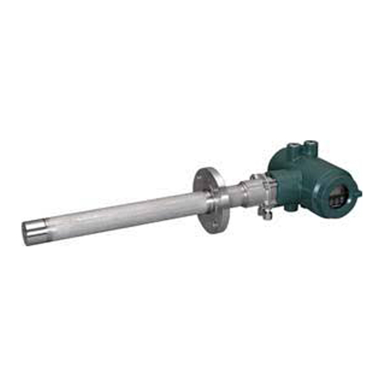
YOKOGAWA ZR402G User Manual
Integrated type zirconia oxygen/humidity
Hide thumbs
Also See for ZR402G:
- User manual (209 pages) ,
- Instruction manual (207 pages) ,
- Technical information (37 pages)

Related Manuals for YOKOGAWA ZR402G


Summary of Contents for YOKOGAWA ZR402G
- Page 1 User’s Manual Model ZR202G Integrated type Zirconia Oxygen/Humidity Analyzer IM 11M12A01-04E IM 11M12A01-04E 11th Edition...
- Page 2 EXAxt ZR.> No. IM 11M12A01-04E 11th Edition : Jul. 2017 (YK) IM 11M12A01-04E 11th Edition : Jul. 19, 2017-00 All Rights Reserved Copyright © 2000, Yokogawa Electric Corporation...
- Page 3 Models and descriptions in this manual are listed below. Models and descriptions in this manual Description in this manual Model Product Name Specification Installation Operation Maintenance CMPL ZR202G Integrated type Oxygen ○ ○ ○ ○ ○ Analyzer ZO21R Probe protector ○...
- Page 4 For the safe use of this equipment WARNING Be sure not to accidentally drop it. Handle safely to avoid injury. Connect the power supply cord only after confirming that the supply voltage matches the rating of this equipment. In addition, confirm that the power is switched off when connecting power supply. Some sample gas is dangerous to people.
-
Page 5: Safety Precautions
The product is provided on an “as is” basis. YOKOGAWA shall have neither liability nor responsibility to any person or entity with respect to any direct or indirect loss or damage arising from using the product or any defect of the product that YOKOGAWA can not predict in advance. IM 11M12A01-04E... - Page 6 • No part of the user’s manuals may be transferred or reproduced without prior written consent from YOKOGAWA. • YOKOGAWA reserves the right to make improvements in the user’s manuals and product at any time, without notice or obligation. • If you have any questions, or you find mistakes or omissions in the user’s manuals, please contact our sales representative or your local distributor.
- Page 7 Special descriptions in this manual This manual indicates operation keys, displays and drawings on the product as follows: Operation keys, displays on the panel Enclosed in [ ]. (Ex. “MODE” key) (Ex. message display → “BASE”) (Ex. data display → “102”...
- Page 8 Batteries are included in this product. Batteries incorporated into this product cannot be removed by yourself. Dispose them together with this product. When you dispose this product in the EU, contact your local Yokogawa Europe B.V.office. Do not dispose them as domestic household waste.
- Page 9 Blank Page...
-
Page 10: Table Of Contents
Toc-1 Model ZR202G Integrated type Oxygen/Humidity Analyzer IM 11M12A01-04E 11th Edition CONTENTS Introduction ....................i Safety Precautions ..................iv CE marking products .................vii Overview ....................1-1 < EXAxt ZR > System Configuration ............... 1-1 1.1.1 System 1 .................... 1-1 1.1.2 System 2 .................... 1-2 1.1.3 System 3 .................... - Page 11 Toc-2 3.1.1 Probe Insertion Hole ................3-1 3.1.2 Installation of the Probe ..............3-2 3.1.3 Installation of the Dust Filter (K9471UA), Dust Guard Protector (K9471UC) Probe Protector (ZO21R) ..........3-2 3.1.4 Installation of ZH21B Dust Protector ..........3-4 Installation of ZA8F Flow Setting Unit ............3-5 Installation of ZR20H Automatic Calibration Unit .........
- Page 12 Toc-3 ZA8F Flow Setting Unit, ZR20H Automatic Calibration Unit ......6-2 Startup ....................... 7-1 Checking Piping and Wiring Connections ............. 7-1 Valve Setup ......................7-1 Supplying Power to Converter ................ 7-2 Operation of Infrared Switch ................7-2 7.4.1 Display and Switches ................. 7-2 7.4.2 Display Configuration .................
- Page 13 Toc-4 8.2.2 Preference Order of Output Hold Value ..........8-7 8.2.3 Output Hold Setting ................8-7 8.2.4 Default Values ..................8-7 Setting Alarms ....................8-8 8.3.1 Alarm Values ..................8-8 8.3.2 Alarm Output Actions ................. 8-8 8.3.3 Alarm Setting..................8-9 8.3.4 Default Values ..................
- Page 14 Toc-5 10.1.1 Oxygen Concentration ..............10-2 10.1.2 Humidity ................... 10-2 10.1.3 Mixing Ratio ..................10-2 10.1.4 Relative Humidity ................10-2 10.1.5 Dew Point ..................10-2 10.1.6 Air Ratio.................... 10-3 10.1.7 Cell Temperature ................10-3 10.1.8 Process Gas Temperature ............... 10-3 10.1.9 C.
- Page 15 Toc-6 11.1.2 Replacing the Sensor Assembly ............11-2 11.1.3 Replacement of the Heater Assembly ..........11-4 11.1.4 Replacement of Dust Filter .............. 11-6 11.1.5 Replacement of O-ring ..............11-6 11.1.6 Stopping and Re-starting Operation ..........11-7 11.2 Inspection and Maintenance of the Converter ..........11-7 11.3 Replacement of Flowmeter for ZR20H Automatic Calibration Unit ..
-
Page 16: Overview
<1. Overview> Overview The EXAxt ZR Integrated type Zirconia Oxygen/Humidity Analyzer is used to monitor and control the oxygen concentration in combustion gases, in boilers and industrial furnaces, for wide application in industries which consume considerable energy-such as steel, electric power, oil and petrochemical, ceramics, pulp and paper, food, or textiles, as well as incinerators and medium/small boilers. -
Page 17: System 2
<1. Overview> ZR202G Integrated type Zirconia Oxygen/Humidity Analyzer Stop valve 100 to 240 V AC Contact input Analog output, contact output Digital output (HART) Calibration gas 100/110/115 200/220/240 V AC ZO21S Standard gas unit F1.1E.ai Figure1.1 Example of System 1 NOTE •... -
Page 18: System 3
<1. Overview> 1.1.3 System 3 This example, System 3, represents typical applications in large boilers and heating furnaces, where is a need to monitor and control oxygen concentration. The reference gas and calibration- time span gas are (clean, dry) instrument air. Zero gas is supplied from a gas cylinder. System 3 uses the ZR20H automatic calibration unit, with auto-switching of the calibration gas. -
Page 19: Exaxt Zr > System Components
<1. Overview> < EXAxt ZR > System Components 1.2.1 System Components Separate type Oxygen Humidity System Components System config. Analyzer Analyzer Ex.1 Ex.2 Ex.3 Model ZR202G Integrated type Zirconia Oxygen Analyzers Model ZO21R Probe Protector for Zirconia Oxygen Analyzers K9471UA Dust Filter for Oxygen Analyzer K9471UC Dust Guard Protector ZH21B Dust protector (only for Humidity Analyzer) Model ZO21S Standard Gas Unit... -
Page 20: Specifications
Oxygen concentration in combustion exhaust gas and mixed gas (excluding inflammable gases). May not be applicable corrosive gas such as ammonia, chlorine is present-check with YOKOGAWA.) (In case of Humidity Analyzer, Water vapor (in vol%) in mixed gases (air and water vapor)) -
Page 21: Zr202G Integrated Type Zirconia Oxygen Analyzer
<2. Specifications> Linearity: (Excluding standard gas tolerance) (Excluding the case where the reference gas is by natural convection) (Use oxygen of known concentration (within the measuring range) as the zero and span calibration gases.) ±1% Maximum value of set range; less than 0 to 25 vol%O range (Sample gas pressure: within ±4.9 kPa) ±3% Maximum value of set range;... - Page 22 Note: When the detector is used in conjunction with a check valve and the ZA8F Flow Setting Unit, the maximum pressure of sample gas is 150 kPa. When with a check valve and the ZR20H Automatic Calibration Unit, it is 200 kPa. If the pressure of your sample gas exceeds these limits, consult with Yokogawa. Probe Length: 0.4, 0.7, 1.0, 1.5, 2.0, 2.5, 3.0 m...
- Page 23 <2. Specifications> Functions (inclused Humidity Analyzer) Display Function: Displays values of the measured oxygen concentration, moisture quantity, mixture ratio, etc. Alarm, Error Display: Displays alarms such as “AL-06” or errors such as “Err-01” when any such status occurs. Calibration Functions: Automatic calibration; Requires the Automatic Calibration Unit. It calibrates automatically at specified intervals.
- Page 24 <2. Specifications> Converter Output: One mA analog output point (4 to 20 mA DC (maximum load resistance of 550Ω)) with mA digital output point (HART) (minimum load resistance of 250Ω). Oxygen analyzer; Range; Any setting between 0 to 5 through 0 to 100 vol% O 1 vol% O , and partial range is available (Maximum range value/ minimum range value 1.3 or more)
- Page 25 <2. Specifications> Model and Codes Style : S1 Model Suffix code Option code Description ZR202G - - - - - - - - - - - - - - - - - - - - - - - - - - - - - - - - - - - - - - Integrated type Zirconia Oxygen/ Humidity Analyzer Length -040...
- Page 26 <2. Specifications> EXTERNAL DIMENSIONS Model ZR202G Integrated type Zirconia Oxygen/Humidity Analyzers Unit: mm 338 to 351 Ø123 Display side L= 0.4, 0.7, Rc1/4 or 1/4NPT 1.0, 1.5, 2.0, Reference gas inlet 2.5, 3.0 (m) 153 to 164 4-G1/2,2-1/2NPT etc. Terminal side Cable connection port 252 to 265 Rc1/4 or 1/4NPT...
- Page 27 <2. Specifications> Model ZR202G...-P Integrated type Zirconia Oxygen/Humidity Analyzer with pressure compensation Unit: mm 342 ± 4 Ø123 Display side L= 0.4, 0.7, Rc1/4 or 1/4NPT 1.0, 1.5, 2.0, Reference gas inlet 2.5, 3.0 (m) Reference gas outlet PIPING 4-G1/2,2-1/2NPT etc. Terminal side PIPING:A Cable connection port...
-
Page 28: Zo21R Probe Protector
<2. Specifications> Hood (Option code /H) Unit: mm ± 4 ± 3 F13.ai Material of HOOD : Aluminum Food Weight : Approx. 800g 2.1.3 ZO21R Probe Protector Used when sample gas flow velocity is approx. 10 m/sec or more and dust particles wears the detector in cases such as pulverized coal boiler of fluidized bed furnace (or burner) to protect the detector from wearing by dust particles. -
Page 29: Zh21B Dust Protector
2-10 <2. Specifications> EXTERNAL DIMENSIONS Unit: mm Flange <1> (with bolts, nuts and washer) Washer (12) gasket (t3.0) Mounting nut (M12) Gas flow SUS316 l (Insert length) l=1050,1550,2050 Dimensions of holes on opposing surface F2-3E.ai Flange<1> JIS 5K 65 FF 4 - Ø15 ANSI Class 150 4 FF 228.6 190.5... -
Page 30: Za8F Flow Setting Unit And Zr20H Automatic Calibration Unit
Approx. 2.3 kg Calibration gas (zero gas, span gas) Consumption: Approx. 0.7 l/min (at calibration time only) NOTE Use instrument air for span calibration gas, if no instrument air is available, contact YOKOGAWA. IM 11M12A01-04E 11th Edition : Jul. 19, 2017-00... - Page 31 2-12 <2. Specifications> Model and Codes Model Suffix code Option code Description ZA8F - - - - - - - - - - - - - - - - - Flow setting unit Joint - - - - - - - - - Rc 1/4 - - - - - - - - - With 1/4 NPT adapter...
- Page 32 2-13 <2. Specifications> External Dimensions Unit : mm (inch) ø6 Hole REFERENCE CHECK REFERENCE SPAN ZERO 2B mounting pipe 235.8 222.8 Calibration gas outlet Span gas inlet Reference gas outlet Zero gas inlet Piping connection port A CHECK SPAN ZERO Model Piping connection port A ZA8F-J*C 5 - Rc1/4...
-
Page 33: Zr20H Automatic Calibration Unit
Vertical mounting — - - - - - - - - Always -A Ask Yokogawa service station for additional mounting of ZR20H to the preinstalled ZR202G. Select the appropriate reference gas of ZR20H according to the one of ZR202G. IM 11M12A01-04E... - Page 34 2-15 <2. Specifications> External Dimensions (1) Horizontal Mounting (-A) Unit: mm Ø80 AUTO CAL. UNIT MODEL ZR20H SUFFIX STYLE SPAN IN REF IN ZERO IN SUPPLY 690kPa MAX. -20 TO 558C AMB.TEMP ZR202G USED WITH 66.5 166.5 Zero gas inlet Rc1/4 or 1/4NPT(Female) Span gas inlet Reference gas inlet Rc1/4 or 1/4NPT(Female)
-
Page 35: Zo21S Standard Gas Unit
2-16 <2. Specifications> ZO21S Standard Gas Unit This is a handy unit to supply zero gas and span gas to the detector in a system configuration based on System 1. It is used in combination with the detector only during calibration. The ZO21S does not conform to CE marking. -
Page 36: Other Equipment
2-17 <2. Specifications> Other Equipment 2.4.1 Dust Filter for Oxygen Analyzer (part no. K9471UA) This filter is used to protect the detector sensor from corrosive dust components or from a high concentration of dust when the oxygen concentration in utility boilers or concrete kilns are to be measured. -
Page 37: Stop Valve (Part No. L9852Cb Or G7016Xh)
2-18 <2. Specifications> Unit: mm Increasing of insertion length 4-Ø6 F11-1.ai 2.4.3 Stop Valve (part no. L9852CB or G7016XH) This valve is mounted on the calibration gas line in the system to allow for manual calibration. This is applied to a system configuration (System 1). Standard Specifications Connection: Rc1/4 or 1/4NPT (Female) -
Page 38: Air Set
2-19 <2. Specifications> Part No. Description K9292DN Joint: Rc 1/4, Material: SUS304 (JIS) K9292DS Joint: 1/4 NPT (F), Material: SUS304 (JIS) Unit: mm K9292DN : Rc 1/4(A),R 1/4(B) K9292DS : 1/4FNPT(A),1/4NPT(Male)(B) Approx. 19 Approx. 54 F30.EPS 2.4.5 Air Set This set is used to lower the pressure when instrument air is used as the reference and span gases. -
Page 39: Zero Gas Cylinder (Part No. G7001Zc)
2-20 <2. Specifications> External Dimensions Unit : mm View A Panel cut dimensions Horizontal Vertical mounting mounting ø15 +0.5 2-ø2.2 2-ø6.5 2-M6 screw depth 8 Panel (Horizontal mounting) Secondary pressure Panel (Vertical mounting) gauge Ø74 Primary Secondary Approx. 122 G7003XF, G7004XF: Rc 1/4 K9473XK, K9473XG: 1/4NPT connector F22_1.ai 2.4.6... -
Page 40: Pressure Regulator (G7013Xf Or G7014Xf) For Gas Cylinder
2-21 <2. Specifications> 2.4.7 Pressure Regulator (G7013XF or G7014XF) for Gas Cylinder This regulator valve is used with the zero gas cylinders. Standard Specifications Primary Pressure: Max. 14.8 MPa G Secondary Pressure: 0 to 0.4 MPa G Connection: Inlet; W22 14 threads, right hand screw Outlet;... -
Page 41: Zr202A Heater Assembly
2-22 <2. Specifications> Pressure regulator G7013XF/ G7014XF Zero gas cylinder (G7001ZC) 2B mounting pipe (158.3) ( Ø60.5 ) F23.ai The oblique line is an opening portion. (Note)The zero gas cylinder and the regulator valve are not included in the E7044KF (case assembly) 2.4.9 ZR202A Heater Assembly Model and Codes... -
Page 42: Installation
<3. Installation> Installation This chapter describes installation of the following equipment: Section 3.1 Model ZR202G Integrated type Zirconia Oxygen/Humidity Analyzer Section 3.2 Model ZA8F Flow Setting Unit Section 3.3 Model ZR20H Automatic Calibration Unit Section 3.4 Case Assembly (E7044KF) for Calibration gas Cylinder Installation of ZR202G Zirconia Oxygen/ Humidity Analyzer The following should be taken into consideration when installing the probe:... -
Page 43: Installation Of The Probe
<3. Installation> (1) Do not mount the probe with the tip higher than the probe base. (2) If the probe length is 2.5 m or more, the detector should be mounted vertically (no more than a 5° tilt). (3) The detector probe should be mounted at right angles to the sample gas flow or the probe tip should point downstream. - Page 44 <3. Installation> When you specify option code /F1, the detector is shipped with the dust filter mounted. Follow this procedure when replacing the filter in the detector. It is recommended that you read Chapter 11 prior to filter mounting, for it is necessary to be familiar with the detector’s construction, especially the sensor assembly.
-
Page 45: Installation Of Zh21B Dust Protector
<3. Installation> (2) Make sure that the sensor assembly mounting screws (four bolts) at the probe tip are not loose. (3) Mount the detector so that the calibration/reference gas inlet faces downward. Unit: mm Gasket (t1.5) Direction of the sample gas flow 2050 Ø60.5 Detector top... -
Page 46: Installation Of Za8F Flow Setting Unit
<3. Installation> (3) Mount the detector so that the calibration gas inlet and the reference gas inlet face downward. Unit : mm Unit : mm Reference gas inlet Calibration gas inlet F3-2E.ai F3-2E.ai Figure 3.6 Installation of the dust filter Installation of ZA8F Flow Setting Unit The following should be taken into consideration: (1) Easy access to the unit for checking and maintenance work. -
Page 47: Installation Of Zr20H Automatic Calibration Unit
<3. Installation> <Wall Mounting> (1) Make a hole in the wall as illustrated in Figure 3.8. Unit: mm 4 - Ø6 hole, or M5 screw F3.13E.ai Figure 3.8 Mounting holes (2) Mount the flow setting unit. Remove the pipe mounting parts from the mount fittings of the flow setting unit and attach the unit securely on the wall with four screws. -
Page 48: Installation Of The Case Assembly (E7044Kf) For Calibration Gas Cylinder
<3. Installation> Unit: mm Horizontal mounting on the ZR202G (-A) Display side Terminal box side Zero gas inlet Rc1/4 or 1/4NPT(Female) 66.5 166.5 Reference gas inlet Span gas inlet Rc1/4 or 1/4NPT(Female) Rc1/4 or 1/4NPT(Female) Vertical mounting on the ZR202G (-B) 166.5 Span gas inlet... -
Page 49: Insulation Resistance Test
<3. Installation> Mounting Mount case assembly on a pipe (nominal JIS 50 A) as follows: (1) Prepare a vertical pipe of sufficient strength (nominal JIS 50A: O.D. 60.5 mm) for mounting the case assembly. (The sum of the case assembly and the calibration gas cylinder weighs approximately 4.2 kg.) (2) Mount the case assembly on the pipe by tightening the nuts with the U-bolt so that the metal fitting is firmly attached to the pipe. - Page 50 <3. Installation> Contact input 1 Insulation Crossover wiring Contact input 2 resistance tester DI-1 DI-2 DI-C DO-1 DO-1 DO-2 DO-2 Remove jumper Crossover wiring plate Insulation Insulation resistance resistance tester tester F3.17E.ai Figure 3.12 IM 11M12A01-04E 11th Edition : Jul. 19, 2017-00...
- Page 51 Blank Page...
-
Page 52: Piping
<4. Piping> Piping This chapter describes piping procedures in the three typical system configurations for EXAxt ZR Integrated type Zirconia Oxygen/Humidity Analyzer. • Ensure that each check valve, stop valve and joints used for piping are not leaking. Especially, when there is any leakage at piping and joints for the calibration gas, it may cause clogging of the piping or incorrect calibration. -
Page 53: Piping Parts For System 1
Mount the stop valve (of a quality specified by YOKOGAWA) through a nipple (found on the local market) as illustrated in Figure 4.2, and mount a joint (also found on the local market) at the stop valve tip. (The stop valve may be mounted on the equipment when the oxygen analyzer is shipped.) -
Page 54: Piping Parts For System 2
Mount the pressure regulator (recommended by YOKOGAWA) on the cylinder. Mount the stop valve or the check valve (recommended by YOKOGAWA) through the nipple (found on the local market) at the calibration gas inlet of the equipment as illustrated in Figure 4.4. -
Page 55: Piping For The Reference Gas
<4. Piping> Piping for the reference gas 6mm (O.D.) by 4mm (I.D.) stainless steel pipe Piping for the calibration gas 6mm (O.D.) by 4mm (I.D.) stainless steel pipe Stop valve or check valve F4.8E.ai Figure 4.4 Piping for the Calibration Gas Inlet 4.2.3 Piping for the Reference Gas Reference gas piping is required between the air source (instrument air) and the flow setting unit,... - Page 56 <4. Piping> Installation of ZR20H Automatic Calibration Unit Unit: mm Horizontal mounting on the ZR202G (-A) Display side Terminal box side Zero gas inlet Rc1/4 or 1/4NPT(Female) 66.5 166.5 Reference gas inlet Span gas inlet Rc1/4 or 1/4NPT(Female) Rc1/4 or 1/4NPT(Female) Vertical mounting on the ZR202G (-B) 166.5...
-
Page 57: Piping For The Oxygen Analyzer With Pressure Compensation
<4. Piping> Piping for the Oxygen Analyzer with Pressure Compensation ZR202G-----P Oxygen Analyzer with pressure compensation may be used in System 2 and System 3. Use this style analyzer whenever the furnace pressure exceeds 5 kPa (see Note). Even if the furnace pressure is high, the detector can measure by adjusting pressure of the probe with the furnace pressure using instrument air. - Page 58 <4. Piping> CAUTION • Use suitable cable glands to completely seal the detector. As far as possible do not stop the instrument air flow, to prevent the sample gas from entering the detector and damaging the zirconia cell. • Connect the stop valve, which is at the calibration gas inlet, directly to the equipment. If piping connections are made between the detector and the needle valve, condensation will result inside the piping and cause the sensor to be damaged when the calibration gas is introduced.
-
Page 59: Piping Parts For Oxygen Analyzer With Pressure Compensation
General parts Reference gas inlet Air set (G7003XF/ K9473XK or G7004XF / K9473XG) recommended by YOKOGAWA Joint for tube connection Rc1/4 or 1/4 NPT General parts Note: Use parts with marking * as required. General parts can be found on the local market. -
Page 60: Wiring
<5. Wiring> Wiring This chapter describes wiring procedures necessary for the EXAxt ZR Integrated type Zirconia Oxygen/Humidity Analyzer. General WARNING NEVER supply current to the converter or any other device constituting a power circuit in combination with the converter, until all wiring is completed. CAUTION This product complies with CE marking. -
Page 61: Terminals For The External Wiring
<5. Wiring> WARNING Cables that withstand temperatures of at least 80 °C should be used for wiring. CAUTION • Select suitable cable O.D. to match the cable gland size. • Protective grounding should be connected in ways equivalent to JIS D style (Class 3) grounding (the grounding resistance is 100 Ω... -
Page 62: Mounting Of Cable Gland
<5. Wiring> Model ZR202G Integrated type Zirconia Oxygen Analyzer Contact output 1 Contact output 2 Contact input 1 Contact input 2 DI-1 DI-2 DI-C DO-1 DO-1 DO-2 DO-2 100 to 240 V AC, Analog output 50 or 60 Hz 4-20 mA DC Digital output F28.EPS The protective grounding for the analyzer shall be connected either the protective ground terminal... -
Page 63: Cable Specifications
<5. Wiring> 5.2.1 Cable Specifications Use a 2-core shielded cable for wiring. 5.2.2 Wiring Procedure (1) M4 screws are used for the terminals. Use crimp-on terminals appropriate for M4 terminal screws for cable connections. Ensure that the cable shield is connected to the FG terminal of the equipment. -
Page 64: Wiring For Ground Terminals
<5. Wiring> 5.3.2 Wiring for Ground Terminals The ground wiring of the analyzer should be connected to either the ground terminal of the equipment case or the terminal inside of the equipment. Proceed as follows: (1) Keep the ground resistance of 100Ω or less (JIS Class D grounding). (2) When connecting the ground wiring to the ground terminal of the equipment case, be sure that the lock washer is in contact with the case surface (see Figure 5.5.). -
Page 65: Cable Specifications
<5. Wiring> 5.5.1 Cable Specifications Use a 2-core or 3-core cable for this wiring. Depending on the number of input(s), determine which cable to use. 5.5.2 Wiring Procedure (1) M4 screws are used for the terminal of the converter. Each cable should be equipped with the corresponding crimp contact. -
Page 66: Components
<6. Components> Components This chapter describes the names and functions of components for the major equipment of the EXAxt ZR Integrated type Zirconia Oxygen/Humidity Analyzer. ZR202G Zirconia Oxygen/Humisity Analyzer Terminal box, Non explosion-proof JIS C0920 / equivalent to IP44D. Equivalent to NEMA 4X/IP66 (Achieved when the cable entry is completely sealed with a cable gland in the recirculation pressure... -
Page 67: Za8F Flow Setting Unit, Zr20H Automatic Calibration Unit
<6. Components> ZA8F Flow Setting Unit, ZR20H Automatic Calibration Unit Reference gas flow setting valve Span gas flow setting valve Zero gas flow setting valve Flowmeter for reference gas Flowmeter for calibration gas F6-4E.ai Figure 6.2 ZA8F Flow Setting Unit Horizontal mounting Vertical mounting Flowmeter for... -
Page 68: Startup
<7. Startup> Startup The following describes the minimum operating requirements — from supplying power to the converter to analog output confirmation to manual calibration. In the figure listed in this manual, the example of the oxygen analyzer is shown mainly. In the case of the humidity analyzer, unit indication may be different. -
Page 69: Supplying Power To Converter
<7. Startup> (2) If instrument air is used as the reference gas, adjust the Air set secondary pressure so that the air pressure of sample gas pressure plus approx. 50 kPa (plus approx. 150 kPa for with check valve) (300 kPa maximum for the ZA8F, 690 kPa maximum for the ZR20H) is obtained. - Page 70 <7. Startup> 4: Decimal point 1: Data display area µ M m N k g a l b b l scftm3 /d /s /h /m > 3: Engineering-unit display area 2: Infrared switch F7.3E.ai Figure 7.4 Infrared switch and the display 1.
-
Page 71: Display Configuration
<7. Startup> 7.4.2 Display Configuration The parameter codes provided for the equipment are used to control the equipment display panels (see below). By selecting appropriate parameter codes, you can conduct calibration and set operation parameters. Figure 7.5 shows the configuration of display items. The parameter codes are listed in groups of seven;... -
Page 72: Entering Parameter Code Selection Display
<7. Startup> 7.4.3 Entering Parameter Code Selection Display This section briefly describes the password entry procedure for entering the parameter code selection display. The password is 1102 - it cannot be changed to a different password. Switch operation Display Description 21.0% >... -
Page 73: Selecting Parameter Codes
<7. Startup> 7.4.4 Selecting Parameter Codes Switch operation Display Description > ∧ Password has been entered and the parameter code selection display has appeared. Character A is flashing, indicating that character A can be changed. > ∧ If you touch the [>] key once, the position of the digit that is flashing will move to the right. - Page 74 <7. Startup> (2) Entering numeric values such as oxygen concentration values and factors Switch operation Display Description > ∧ 00.0 The set value is displayed after the parameter code selection. An example of entering "9.8" is given below. (The currently set value is 0.0) >...
-
Page 75: Confirmation Of Equipment Type Setting
<7. Startup> Confirmation of Equipment Type Setting This equipment can be used for both the Oxygen Analyzer and the Humidity Analyzer. If you choose optional specification /HS at the time of purchase, the equipment is set for the Humidity Analyzer. Before setting the operating data, be sure to check that the desired model has been set. -
Page 76: Selection Of Measurement Gas
<7. Startup> Selection of Measurement Gas Combustion gases contain moisture created by burning hydrogen in the fuel. If this moisture is removed, the oxygen concentration might be higher than before. You can select whether the oxygen concentration in a wet gas is to be measured directly, or compensated for its dry-gas value before use. - Page 77 7-10 <7. Startup> Table 7.5 Minimum and Maximum Value Setting Procedure Switch operation Display Description > ∧ Display after the password has been entered. > ∧ Set the oxygen concentration at 4 mA. Change the parameter code to C11. Touch the [∧] key to switch to Group C. >...
-
Page 78: Humidity Analyzer -Minimum Current (4 Ma) And Maximum Current (20 Ma) Settings
7-11 <7. Startup> 7.7.2 Output Range Setting Select any one of the analog output settings — oxygen, humidity, and mixing ratio. If the /HS option was specified at the time of purchase, the equipment is a humidity analyzer. For other than this setting, the analyzer is an oxygen analyzer. -
Page 79: Setting Display Item
7-12 <7. Startup> Switch operation Display Description > ∧ Touch the [>] key to move the position of the digit that is flashing to the right. > ∧ Touch the [∧] key to change the number 2 in C25 to “8.” >... -
Page 80: Humidity Analyzer - Setting Display Item
7-13 <7. Startup> 7.8.2 Humidity Analyzer - Setting Display Item Display items are those items that are displayed on the basic panel display. Parameter code A00 or F08 is used to set the display items as shown in the table below. If the humidity analyzer /HS option was specified at the time of purchase, the equipment is a humidity analyzer. -
Page 81: Checking Contact I/O
7-14 <7. Startup> 7.10 Checking Contact I/O Conduct a contact input and output check as well as an operation check of the solenoid valves for the optional automatic calibration unit. Table 7.10 Parameter Codes for Checking Contact I/O Check item Parameter code Set value and contact action Contact output 1 Open... -
Page 82: Checking Calibration Contact Output
7-15 <7. Startup> CAUTION If you conduct an open-close check for the contact output 2, Error 1 (cell voltage failure) or Error 2 (heater temperature abnormal) will occur. This is because the built-in heater power of the detector, which is connected to contact output 2, is turned off during the above check. So, if the above error occurs, reset the equipment or turn the power off and then back on to restart (refer to Section 10.4, “Reset,”... -
Page 83: Checking Input Contacts
7-16 <7. Startup> 7.10.3 Checking Input Contacts Follow Table 7.13 to check the input contacts. The table uses an example with input contact 1. Table 7.13 Checking Input Contacts Switch operation Display Description > ∧ Display after the password has been entered. >... - Page 84 7-17 <7. Startup> (3) Oxygen concentration in span gas Enter the span gas oxygen concentration for calibration. If instrument air is used, enter 21 vol % O . When using the ZO21S Standard Gas Unit (for use of the atmospheric air as a span gas), use a hand-held oxygen analyzer to measure the actual oxygen concentration, and then enter it.
- Page 85 7-18 <7. Startup> Table 7.15 Calibration Setup Procedure Switch operation Display Description > ∧ Display after the password has been entered. > ∧ Set the zero gas concentration. Switch the parameter code to B01. Here, set 0.98%. > ∧ 001.00 Touch the [ENT] key to display the currently set value.
-
Page 86: Manual Calibration
7-19 <7. Startup> 7.11.2 Manual Calibration The following describes how to conduct a calibration. Preliminary Before conducting a manual calibration, be sure that the ZA8F Flow Setting Unit zero gas flow valve is fully closed. Open the zero gas cylinder pressure regulator so that the secondary pressure will be a sample gas plus approx. - Page 87 7-20 <7. Startup> Switch operation Display Description > ∧ 0.98 Touch the [ENT] key to display the calibration gas value. This value must be the zero gas concentration set in Section 7.10.1, "Calibration Setup," earlier in this manual. To cancel the above, touch the [>] key and [ENT] key together, then the display returns to "ZEro Y."...
-
Page 88: Detailed Data Setting
<8. Detailed Data Setting> Detailed Data Setting Current Output Setting 8.1.1 Oxygen Analyzer_Current Output Setting This section describes setting of the analog output range. Table 8.1 shows parameter codes for the set items. Table 8.1 Current Output Parameter Codes Set item Parameter code Set value Analog output... -
Page 89: Input Ranges
<8. Detailed Data Setting> NOTE When you select logarithmic mode in Section 8.1.3, “Output Mode,” later in this manual, the oxygen concentration, humidity reading, and mixing ratio remain constant at 0.1% O , 0.1% H and 0.01 kg/kg respectively. 8.1.3 Setting Minimum Oxygen Concentration (at 4 mA) and Maximum Oxygen Concentration (at 20 mA) Set the oxygen concentration values at 4 mA and 20 mA. - Page 90 <8. Detailed Data Setting> If you do not observe this restriction, the measurement will be invalid, and any previous valid value will be used. The gray area in figure represents the valid setting range. Setting example 1 If the range minimum (corresponding to 4 mA output) is set to 10 vol%O then range maximum (corresponding to 20 mA output) must be at least 13 vol%O Setting example 2...
- Page 91 <8. Detailed Data Setting> Ranges over which oxygen concentrations can be set Outside ranges Minimum humidity (for a 4-mA current), % H F8-2E.ai Figure B Max. and Min. Humidity Set Ranges “Mixing ratio” setting range The minimum mixing ratio is set to 0 kg/kg or ranges from 0.201 to 0.625 kg/kg. The maximum “mixing ratio”...
-
Page 92: Entering Output Damping Constants
<8. Detailed Data Setting> 8.1.6 Entering Output Damping Constants If a measured value adversely affected by a rapid change in the sample gas oxygen concentration is used for the control means, frequent on-off actions of the output will result. To avoid this, the converter allows the setting of output damping constants ranging from 0 to 255 seconds. -
Page 93: Definition Of Equipment Status
<8. Detailed Data Setting> 8.2.1 Definition of Equipment Status (1) During warm-up “During warm-up” is the time required after applying power until the sensor temperature stabilizes at 750°C, and the equipment is in the measurement mode. This status is that the sensor temperature is displayed on the basic panel. -
Page 94: Preference Order Of Output Hold Value
<8. Detailed Data Setting> In a semi-automatic calibration, “during calibration” is the time, starting when a calibration instruction is executed with an infrared switch or a contact input, to make a series of calibrations, until the preset output stabilization time elapses. In an automatic calibration, “during calibration”... -
Page 95: Setting Alarms
<8. Detailed Data Setting> Setting Alarms The analyzer enables the setting of four alarms high-high, high, low, and low-low alarms depending upon the oxygen concentration. The following section sets forth the alarm operations and setting procedures. 8.3.1 Alarm Values (1) High-high and high alarm values High-high alarms and high alarms are issued when they are set to be detected with parameter codes “D41”... -
Page 96: Alarm Setting
<8. Detailed Data Setting> (3) Although oxygen concentration measurement “C” has fallen lower than the hysteresis set value, that measurement exceeds the hysteresis set value before the preset delayed time has elapsed. So, the alarm is not canceled. (4) Oxygen concentration measurement “D” has fallen below the hysteresis set value and the preset delayed time during measurement has elapsed, so the alarm is canceled. -
Page 97: Default Values
8-10 <8. Detailed Data Setting> CAUTION Even with alarms set, if “Not detected” has been set in the above alarm detection, no alarm is issued. Be sure to set “Detected” in the above alarm detection if you use alarm features. 8.3.4 Default Values When the analyzer is delivered, or if data are initialized, the default alarm set values are as... -
Page 98: Setting Output Contact
8-11 <8. Detailed Data Setting> Table 8.9 Setting Output Contacts Operating state When no power is applied to this equipment Output contact 1 Open (de-energized) or closed Open (energized) selectable. Output contact 2 Closed (de-energized) only. Closed 8.4.2 Setting Output Contact Set the output contacts following Table 8.10. -
Page 99: Default Values
8-12 <8. Detailed Data Setting> 8.4.3 Default Values When the analyzer is delivered, or if data are initialized, output contacts are by default as shown in Table 8.11. Table 8.11 Output Contact Default Settings Item Output contact 1 Output contact 2 High-high alarm High alarm Low alarm... -
Page 100: Setting Input Contact
8-13 <8. Detailed Data Setting> CAUTION • Measurement range switching function by an external contact input is available for analog output 1 only and the range is fixed to 0-25%O • To conduct a semi-automatic calibration, be sure to set the Calibration setup mode to “Semi- automatic”... -
Page 101: Setting Periods Over Which Average Values Are Calculated And Periods Over Which Maximum And Minimum Values Are Monitored
8-14 <8. Detailed Data Setting> Table 8.14 Data-and-time Settings Switch operation Display Description > ∧ Select the parameter code F10. > ∧ 00.01.01 If you touch the [ENT] key, the current date will be displayed. The display on the left indicates the date - January 1, 2000. To set June 21, 2000, follow the steps below: >... -
Page 102: Setting Fuels
8-15 <8. Detailed Data Setting> Table 8.15 Parameter Codes for Average, Maximum and Minimum Values Set item Parameter code Set range Units Periods over which average values 1 to 255 Hours are calculated Periods over which maximum 1 to 255 Hours and minimum values are monitored Default Value... - Page 103 8-16 <8. Detailed Data Setting> For liquid fuel Amount of water vapor in exhaust gas (Gw) = (1/100) {1.24 (9h + w)} (m /kg) Theoretical amount of air (Ao) = 12.38 x (Hl/10000) – 1.36 (m /kg) Low calorific power = Hl X value = (3.37 / 10000) x Hx –...
- Page 104 8-17 <8. Detailed Data Setting> 0.046 0.044 0.042 0.040 0.038 0.036 0.034 0.032 0.030 0.028 Wet-bulb 0.026 Absolute temperature, °C humidity, kg/kg 0.024 0.022 0.020 0.018 0.016 0.014 0.012 0.010 0.008 0.006 0.004 0.002 0.000 12 14 16 18 20 22 24 26 28 30 32 34 36 38 40 Dry-bulb temperature, °C...
- Page 105 8-18 <8. Detailed Data Setting> Table 8.16 Fuel Data • For liquid fuel Fuel Chemical component Amount of combustion Calorific power Theoretical Specific properties amount of (weight percentage) gas Nm kJ/kg weight value air for kg/l combustion Type Higher Lower Total O SO content...
-
Page 106: Setting Measurement Gas Temperature And Pressure
8-19 <8. Detailed Data Setting> Procedure Use the parameter code table below to set fuel values. Table 8.17 Setting Fuel Values Set item Parameter code Set value Engineering units Amount of water vapor in exhaust gas 0 to 5 /kg (m Theoretical amount of air 1 to 20 /kg (m... -
Page 107: Setting Purging
8-20 <8. Detailed Data Setting> Default Values When the analyzer is delivered or data are initialized, the parameters are by default as shown in Table 8.20. Table 8.20 Parameter Codes for Exhaust Gas Temperature and Pressure Settings Item Default setting Exhaust gas temperature 300°C Exhaust gas pressure... -
Page 108: Calibration
<9. Calibration> Calibration Calibration Briefs 9.1.1 Principle of Measurement with a zirconia oxygen analyzer This section sets forth the principles of measurement with a zirconia oxygen analyzer before detailing calibration. A solid electrolyte such as zirconia allows the conductivity of oxygen ions at high temperatures. Therefore, when a zirconia-plated element with platinum electrodes on both sides is heated up in contact with gases having different oxygen partial pressures on each side, the element shows the action of the concentration cell. -
Page 109: Measurement Principle Of Zirconia Humidity Analyzer
<9. Calibration> 0.51 vol%O ,81.92mV(Zero origin of calibration) Cell voltage (mV) 21.0 vol%O , 0mV (Span origin of calibration) 21.0 Oxygen concentration (vol % O F9.1E.ai Figure 9.1 Oxygen Concentration in a Measurement Gas vs. Cell Voltage (21 vol%O Equivalent) The measurement principles of a zirconia oxygen analyzer have been described above. - Page 110 <9. Calibration> From the above equations (1) and (2), we obtain: E = -K log y/a = -Klog [(100 – x) 30.21] /21 = - K log (1 –0.01 x) ……………… Equation (3) where, K = Constant Using the above equation (3), we can calculate the water vapor in vol % from the electromotive force.
-
Page 111: Calibration Gas
<9. Calibration> Humidity, vol % H Mixing ratio, kg/kg 9 10 11 12 13 14 15 16 17 18 19 20 21 22 Oxygen concentration, vol % O Oxygen concentration vs. Humidity, Mixing ratio F9-3E.ai Figure 9.4 9.1.3 Calibration Gas A gas with a known oxygen concentration is used for calibration. -
Page 112: Characteristic Data From A Sensor Measured During Calibration
<9. Calibration> 81.92 Zero origin Calibration curve before correction Cell electromotive force, mV Corrected calibration curve (theoretical calibration curve) Span origin 21.0 0.51 Zero gas concentration Span gas concentration Oxygen concentration (vol%O Zero correction ratio = (B/A) x 100 (%) Correctable range: 100 ±... -
Page 113: Calibration Procedures
<9. Calibration> (3) Response time You can monitor the response time provided that a two-point calibration has been done in semi-automatic or automatic calibration. (4) Cell’s internal resistance The cell’s internal resistance gradually increases as the cell (sensor) deteriorates. You can monitor the values measured during the latest calibration. -
Page 114: Zero Gas Concentration
<9. Calibration> 9.2.3 Zero gas Concentration Set the oxygen concentration for zero calibration. Enter the oxygen concentration for the zero gas in the cylinder used. 9.2.4 Span gas Concentration Set the oxygen concentration for span calibration. If instrument air is used as the span gas, enter 21 %O When using the ZO21S Standard Gas Unit (for use of the atmospheric air as a span gas), use a hand-held oxygen analyzer to measure the actual oxygen concentration, and then enter it. - Page 115 <9. Calibration> • When the calibration mode is in automatic: In addition to the above hold (output stabilization) time and calibration time, set the interval, start date, and start time. Interval means the calibration intervals ranging from 000 days, 00 hours to 255 days, 23 hours.
-
Page 116: Calibration
<9. Calibration> Table 9.2 Default Settings for Calibration Item Default Setting Calibration mode Manual Calibration procedure Span - zero Zero gas (oxygen) concentration 1.00% Span gas (oxygen) concentration 21.00% Hold (Output stabilization) time 10 minutes, 00 seconds Calibration time 10 minutes, 00 seconds Calibration interval 30 days, 00 hours Start date and time... -
Page 117: Automatic Calibration
9-10 <9. Calibration> 9.3.3 Automatic Calibration No execution operations are required for automatic calibration. Automatic calibration starts in accordance with a preset start day and time. Calibration is then executed at preset intervals. NOTE Before conducting a semi-automatic or automatic calibration, run the automatic calibration unit beforehand to obtain a calibration flow of 600 ±... -
Page 118: Other Functions
10-1 <10. Other Functions> Other Functions 10.1 Detailed Display Select the desired parameter code to display the detailed operation data (see Table 10.1, “Parameter Codes for Detailed Operation Data”. NOTE Refer to Section 7.8, “Setting Display Item”, for parameter code “A00”. Table 10.1 Parameter Codes for Detailed Operation Data Engineering... -
Page 119: Oxygen Concentration
10-2 <10. Other Functions> Min. oxygen concentration Calibration history 7 YY.MM.DD/ HH.MM Occurrence of minimum oxygen YY.MM.DD/ Calibration history 8 YY.MM.DD/ concentration HH.MM HH.MM Average oxygen concentration Calibration history 9 YY.MM.DD/ HH.MM Maximum humidity Time YY.MM.DD/ HH.MM Occurrence of maximum humidity YY.MM.DD/ Software revision HH.MM... -
Page 120: Air Ratio
10-3 <10. Other Functions> The water vapor pressure in the moist air can be obtained from the gas pressure and volume ratio (= pressure ratio), as given below. e = P x H where, e = Water vapor pressure in moist air P = Gas pressure H = Humidity (volume ratio) Use the above equation to find the water vapor in the moist air, and use the theoretical equation... -
Page 121: Cell Voltage
10-4 <10. Other Functions> 10.1.11 Cell Voltage The cell (sensor) voltage will be an index to determine the amount of degradation of the sensor. The cell voltage corresponds to the oxygen concentration currently being measured. If the indicated voltage approximates the ideal value (corresponding to the measured oxygen concentration), the sensor will be assumed to be normal. -
Page 122: Cell's Internal Resistance
10-5 <10. Other Functions> Five minutes maximum Response time 100% 10% of analog output span Time Start calibration Calibration complete The response time is obtained after the corrected calibration curve has been found. The response time is calculated, starting at the point corresponding to 10% of the analog output up to the point at 90% of the analog output span. -
Page 123: Oxygen Concentration (With Time Constant), Humidity (With Time Constant), And Mixing Ratio (With Time Constant)
10-6 <10. Other Functions> 10.1.19 Oxygen Concentration (with time constant), Humidity (with time constant), and Mixing Ratio (with time constant) When the output damping is specified in the mA-output range setting, the corresponding time constant is also displayed. 10.1.20 Maximum Oxygen Concentration, Humidity, and Mixing Ratio The maximum oxygen concentration and the time of its occurrence during the period specified in the Averaging display are displayed. -
Page 124: History Of Calibration Time
10-7 <10. Other Functions> 10.1.24 History of Calibration Time The calibration-conducted dates and times for the past ten calibrations are stored in memory. 10.1.25 Time The current date and time are displayed. These are backed up by built-in batteries, so no adjustment is required after the power is switched off. -
Page 125: Initialization Procedure
10-8 <10. Other Functions> 10.3 Initialization Procedure Follow the table below to initialize parameters. The password for initialization is 1255. Table 10.5 Initialization Procedure Switch operation Display Description > ∧ Enter the parameter code for the item to be initialized. The following show an example of entering "F30."... - Page 126 10-9 <10. Other Functions> (1) Error 1 if the cell voltage is defective (2) Error 2 if a temperature alarm occurs (3) Error 3 if the A/D converter is defective (4) Error 4 if an EEPROM write error occurs For details on error occurrence, consult Chapter 12, “Troubleshooting”, later in this manual. If any of the above problems occurs, the equipment turns off the power to the detector heater.
- Page 127 10-10 <10. Other Functions> Table 10.7 Parameter Codes for Oxygen Analyzer Display-related Items in Group A Engineering Engineering Code Item Code Item unit unit Selection 0 Oxygen concentration Span correction ratio 0 of display 1 Oxygen analyzer (0.0) Span correction ratio 1 items 2 Oxygen analyzer (0.0) Span correction ratio 2...
- Page 128 10-11 <10. Other Functions> Calibration-related Items in Group B Code Item Tuning Engineering unit Default setting Zero gas concentration 0.3 to 100 1% O Span gas concentration 4.5 to 100 21% O Calibration mode 0 Manual calibration Manual calibration 1 Semi-automatic and manual calibration 2 Automatic, semi-automatic, and manual calibration...
- Page 129 10-12 <10. Other Functions> Output-related Items in Group C Code Item Tuning Engineering unit Default setting C01 Analog output 0 Oxygen concentration Oxygen concentration 1 Amount of moisture content 2 Mixed ratio C03 Output mode 0 Linear Linear 1 Logarithm C04 Output during warm-up 0 Held at 4 mA 1 Held at 20 mA...
- Page 130 10-13 <10. Other Functions> Contact-related Items in Group E Code Item Tuning Engineering unit Default setting Selection of input contact 1 0 Invalid Invalid 1 Calibration gas pressure decrease 2 Measurement range change 3 Calibration start 4 Detection of non-combusted gas Selection of input contact 2 0 Invalid Invalid 1 Calibration gas pressure decrease...
- Page 131 10-14 <10. Other Functions> Equipment Setup and Others in Group F Code Item Tuning Engineering unit Default setting Equipment setup 0 Oxygen analyzer Oxygen analyzer 1 Humidity analyzer Selection of measurement 0 Wet 1 Dry Selection of temperature 0 degree C degree C units 1 degree F...
- Page 132 10-15 <10. Other Functions> Table 10.8 Parameter Codes for Humidity Analyzer Display-related Items in Group A Engineering Engineering Code Item Code Item unit unit Selection 0 Oxygen concentration Span correction ratio 0 of display 1 Oxygen analyzer (0.0) Span correction ratio 1 items 2 Oxygen analyzer (0.0) Span correction ratio 2...
- Page 133 10-16 <10. Other Functions> Maximum mixing ratio kg/kg Occurrence of max. mixing ratio YY.MM.DD/ HH.MM Minimum mixing ratio kg/kg Occurrence of min. mixing ratio YY.MM.DD/ HH.MM Average mixing ratio kg/kg Note1: “/” indicates that both are displayed alternately. Note2: Parameter codes with no items in the above table are not used in the oxygen analyzer. Calibration-related Items in Group B Code Item...
- Page 134 10-17 <10. Other Functions> Output-related Items in Group C Code Item Tuning Engineering unit Default setting C01 Analog output 0 Oxygen concentration Humidity 1 Amount of moisture content 2 Mixed ratio C03 Output mode 0 Linear Linear 1 Logarithm C04 Output during warm-up 0 Held at 4 mA 1 Held at 20 mA 2 Set value remains held.
- Page 135 10-18 <10. Other Functions> Alarm-related Items in Group D Code Item Tuning Engineering unit Default setting D01 Oxygen concentration, 0 to 100 100% O high-high alarm setpoint D02 Oxygen concentration, 0 to 100 100% O high alarm setpoint D03 Oxygen concentration, 0 to 100 0% O low alarm setpoint...
- Page 136 10-19 <10. Other Functions> D54 Mix ratio, low-low alarm 0 Not detected Not detected detection 1 Detection Contact-related Items in Group E Code Item Tuning Engineering unit Default setting Selection of input contact 1 0 Invalid Invalid 1 Calibration gas pressure decrease 2 Measurement range change 3 Calibration start 4 Detection of non-combusted gas...
- Page 137 10-20 <10. Other Functions> Equipment Setup and Others in Group F Code Item Tuning Engineering unit Default setting Equipment setup 0 Oxygen analyzer Not initialized 1 Humidity analyzer Selection of temperature 0 degree C degree C units 1 degree F Selection of pressure units 0 kPa 1 psi...
-
Page 138: Handling Of The Zo21S Standard Gas Unit
10-21 <10. Other Functions> 10.5 Handling of the ZO21S Standard Gas Unit The following describe how to flow zero and span gases using the ZO21S Standard Gas Unit. Operate the ZO21S Standard Gas Unit, for calibrating a system classified as System 1, according to the procedures that follow. -
Page 139: Calibration Gas Flow
10-22 <10. Other Functions> To install the gas cylinder, follow these steps: (1) Attach the zero gas valves onto the gas cylinder. First, turn the valve regulator of the zero gas valves counterclockwise to completely retract the needle at the top from the gasket surface. -
Page 140: Methods Of Operating Valves In The Za8F Flow Setting Unit
10-23 <10. Other Functions> (4) After the measured oxygen concentration is stabilized, touch the [ENT] key, then all the digits flash. Touch the [ENT] key again to display “ZEro Y”. Disconnect the power cord to stop the pump. <Flow of zero gas> Touch the [ENT] key to display a zero gas value set with the parameter code B01. -
Page 141: Preparation Before Calibration
10-24 <10. Other Functions> 10.6.1 Preparation Before Calibration To operate the ZA8F Flow Setting Unit, prepare for calibration as follows: (1) Check for a complete closing of the zero gas flow setting valve in the unit and open the regulator valve for the zero gas cylinder until the secondary pressure is sample gas pressure plus approx. -
Page 142: Inspection And Maintenance
11-1 <11. Inspection and Maintenance> Inspection and Maintenance This chapter describes the inspection and maintenance procedures for the EXAxt ZR Zirconia Oxygen/Humidity Analyzer to maintain its measuring performance and normal operating conditions. WARNING Do NOT touch the probe if it has been in operation immediately just before being checked. (The sensor at the tip of the probe heats up to 750°C during operation. -
Page 143: Replacing The Sensor Assembly
11-2 <11. Inspection and Maintenance> Exploded view of components Calibration gas tube (with outside diameter of 2 to 2.5 mm) F11.1E.ai Figure 11.1 Cleaning the Calibration Gas Tube 11.1.2 Replacing the Sensor Assembly The performance of the sensor (cell) deteriorates as its surface becomes soiled during operation. Therefore, you have to replace the sensor when its life expectancy expires, for example, when it can no longer satisfy a zero correction ratio of 100 ±... - Page 144 11-3 <11. Inspection and Maintenance> (5) Clean the sensor assembly, especially the metal O-ring contact surface to remove any contaminants adhering to that part. If you can use any of the parts from among those removed, also clean them up to remove any contaminants adhering to them. (Once the metal O-ring has been tightened, it can no longer be used.
-
Page 145: Replacement Of The Heater Assembly
11-4 <11. Inspection and Maintenance> Metal O-ring Sensor (cell) U-shaped pipe support Dust filter Bolts (four) (optional) Probe Contact Filter U-shaped pipe Washers (four) 1/8 turn – tighten bolts 1/8 turn F11.3E.ai (approximately 45°) each Figure 11.3 Exploded View of Sensor Assembly NOTE Optional Inconel bolts have a high coefficient of expansion. - Page 146 11-5 <11. Inspection and Maintenance> View A-A F11.4E.ai Figure 11.4 Exploded View of Detector IM 11M12A01-04E 11th Edition : Jul. 19, 2017-00...
-
Page 147: Replacement Of Dust Filter
11-6 <11. Inspection and Maintenance> Replacement of heater assembly Refer to Figure 11.4 as an aid in the following discussion. Remove U-shaped pipe support , U-shaped pipe , Filter and the sensor (cell) , following Section 11.1.2, earlier in this manual. Remove the two screws that tighten the cover and slide it to the flange side. -
Page 148: Stopping And Re-Starting Operation
11-7 <11. Inspection and Maintenance> 11.1.6 Stopping and Re-starting Operation <Stopping Operation> When operation is stopped, take care of the followings so that the sensor of the detector cannot become unused. CAUTION When operating an instrument such as boiler or industrial furnace is stopped with the zirconia oxygen analyzer operation, moisture can condensate on the sensor portion and dusts may stick to it. -
Page 149: Fuse Rating
11-8 <11. Inspection and Maintenance> SCREW Cover of Display F11.6E.ai F11.5E.ai Figure 11.5 Cover of Display Figure 11.6 Location of Screw (4) Disconnect the three connectors from the printed-circuit board, as shown in Figure 11.7, by holding the connector housing. Do not pull the leadwire out to remove the connectors, otherwise, disconnection may result. -
Page 150: Replacement Of Flowmeter For Zr20H Automatic Calibration Unit
11-9 <11. Inspection and Maintenance> 11.3 Replacement of Flowmeter for ZR20H Automatic Calibration Unit (1) Remove pipe holding piping fitting (2) Remove bolts holding flowmeter, and replace it. A white back plate (to make the float easy to see) is attached. The end of the pin holding down the back plate must be on the bracket side. - Page 151 Blank Page...
-
Page 152: Troubleshooting
12-1 <12. Troubleshooting> Troubleshooting This chapter describes errors and alarms detected by the self-diagnostic function of the converter. This chapter also describes the check and restoration methods to use when problems other than the above occur. 12.1 Displays and Measures to Take When Errors Occur 12.1.1 What is an Error? -
Page 153: Measures To Take When An Error Occurs
5) Remove the probe to gain access to the two connectors (four connectors for the optional automatic calibration unit), as indicated in Figure 12.2. Check these connectors are properly connected. 6) If Error-1 still occurs, the electronics may be defective. Contact your local Yokogawa service or sales representative. Error-2: Heater Temperature Failure This error occurs if the detector heater temperature does not rise during warm-up, or if the temperature falls below 730°C or exceeds 780°C after warm-up is completed. - Page 154 F12.3E.ai Figure 12.3 (4) If the inspection indicates that the thermocouple is normal, the electronics may be defective. Consult your local Yokogawa service or sales representative. Error-3: A/D Converter Failure/Error-4: Writing-to-memory Failure • A/D Converter Failure It is suspected that a failure has occurred in the A/D converter mounted in the converter electronics.
-
Page 155: Displays And Measures To Take When Alarms Are Generated
12-4 <12. Troubleshooting> 12.2 Displays and Measures to Take When Alarms are Generated 12.2.1 What is an Alarm? When an alarm is generated, the alarm indication blinks in the display to notify of the alarm (Figure 12.3). Pressing the alarm indication displays a description of the alarm. Alarms include those shown in Table 12.2. - Page 156 12-5 <12. Troubleshooting> Alarm 6: Zero Calibration Coefficient Alarm In calibration, this alarm is generated when the zero correction ratio is out of the range of 100 ± 30% (refer to Section 9.1.4, “Compensation”). The following can be considered the causes for this: (1) The zero gas oxygen concentration does not agree with the value of the zero gas concentration set (refer to Section 9.2,“Calibration Procedures.)”...
- Page 157 12-6 <12. Troubleshooting> Alarm 7: Span Calibration Coefficient Alarm In calibration, this alarm is generated when the span gas correction ratio is out of the range of 0 ± 18% (refer to Section 9.1.4, “Compensation”). The following are suspected as the cause: (1) The oxygen concentration of the span gas does not agree with the value of the span gas set “Calibration setup.”...
- Page 158 If this alarm occurs even when the ambient temperature is under 55°C, the electronics may be defective. Contact your local Yokogawa service or sales representative. Alarm 11: Thermocouple Voltage Alarm This alarm is generated when the emf (voltage) of thermocouple falls below -5 mV (about -170°C) or exceeds 42.1 mV (about 1020°C).
-
Page 159: Measures When Measured Value Shows An Error
<Corrective action> When the battery low alarm occurs, remember that the battery cannot be replaced by the user. Contact your Yokogawa service representative. NOTE Battery life varies with environmental conditions. * If power is applied to the instrument continuously, then the battery should not run down, and life is typically about ten years. -
Page 160: Measured Value Lower (Higher For Humidity Analyzer) Than True Value
12-9 <12. Troubleshooting> (2) Moisture content in a reference gas changes (increases) greatly. If air at the detector installation site is used for the reference gas, large change of moisture in the air may cause an error in measured oxygen concentration value (vol% O When this error is not ignored, use a gas in which moisture content is constant such as instrument air in almost dry condition as a reference gas. -
Page 161: Measurements Sometimes Show Abnormal Values
12-10 <12. Troubleshooting> 12.3.3 Measurements Sometimes Show Abnormal Values <Cause and Measure> (1) Noise may be mixing in with the converter from the detector output wiring. Check whether the equipment is securely grounded. Check whether or not the signal wiring is laid along other power cords. (2) The converter may be affected by noise from the power supply. -
Page 162: Customer Maintenance Parts List
Cal. Gas Tube Assembly K9470ZL Cal. Gas Tube Assembly for Option code "/C" CMPL 11M12A01-04E All Rights Reserved, Copyright © 2000, Yokogawa Electric Corporation. Subject to change without notice. 1st Edition : Aug. 2000 (YK) 9th Edition : Feb. 2016 (YK) - Page 163 Hood for ZR202G ZR202G_F.ai Item Part No. Description K9472UF Hood CMPL 11M12A01-04E 9th Edition : Feb. 2016 (YK)
-
Page 164: Customer Maintenance Parts List
SPAN IN REF IN ZERO IN Item Part No. Description K9473XC Flowmeter CMPL 11M12A01-12E All Rights Reserved, Copyright © 2001, Yokogawa Electric Corporation. Subject to change without notice. 1st Edition : Feb. 2001 (YK) 4th Edition : Feb. 2016 (YK) -
Page 166: Customer Maintenance Parts List
Table 1 Power Pump AC 100 V E7050AU AC 200 V E7050AV CMPL 11M3D1-01E All Rights Reserved, Copyright © 2000, Yokogawa Electric Corporation. Subject to change without notice. 1st Edition : Jan. 2000 (YK) 4th Edition : Mar. 2011 (YK) -
Page 168: Revision Information
Revision Information Manual Title : Model ZR202G Integrated type Oxygen/Humidity Analyzer Manual No. : IM 11M12A01-04E Jul. 2017/11th Edition Changed flange materials of ZR202G, ZO21R and ZH21B. (pages 2-3, 2-6 to 2-11) May 2017/10th Edition Addition RoHS etc. (pages i, v, vii, 2-2) Feb. - Page 169 12.2.1 Corrected explanation of Alarm 10 Added Filter to CMPL 11M12A01-04E, and added ZR20H Automatic Calibration Unit to CMPL 11M12A01-12E Oct. 2000/1st Edition Newly published Yokogawa Electric Corporation 2-9-32 Nakacho, Musashino-shi, Tokyo 180-8750, JAPAN Homepage: http://www.yokogawa.com/ IM 11M12A01-04E 11th Edition : Jul. 19, 2017-00...
Need help?
Do you have a question about the ZR402G and is the answer not in the manual?
Questions and answers