
Subscribe to Our Youtube Channel
Related Manuals for YOKOGAWA ZR22S


Summary of Contents for YOKOGAWA ZR22S
- Page 1 User’s Manual Model ZR22S, ZR402G Separate type Explosion-proof Zirconia Oxygen Analyzer IM 11M13A01-02E IM 11M13A01-02E 7th Edition...
- Page 2 Introduction Thank you for purchasing the ZR22S, ZR402G Separate type Explosion-proof Zirconia Oxygen Analyzer. Please read the following respective documents before installing and using the ZR22S, ZR402G Separate type Explosion-proof Zirconia Oxygen Analyzer. The related documents are as follows. General Specifications...
- Page 3 ZA8F Flow setting unit (for manual calibration use) ZR40H Automatic Calibration unit Auxiliary ejector assembly for high temperature use (Part No. E7046EC, E7046EN) Calibration gas unit case (Part No.
- Page 4 ATEX Documentation This procedure is only applicable to the countries in European Union. IM 11M13A01-02E...
- Page 5 The ZR22S is connected to a ZR402G or AV550G* that is mounted in a non-hazardous area. The ambient temperature is in the range -20 to +60°C. The surface temperature of the ZR22S is not over the temperature class T2 (300°C)* *1: Refer to IM 11M12D01-01E *2: The terminal box temperature does not exceed 150ºC...
- Page 6 However, should any errors or omissions come to the attention of the user, please contact the nearest Yokogawa Electric representative or sales office. • This manual does not cover the special specifications. This manual may not be changed on any change of specification, construction and parts when the change does not affect the functions or performance of the product.
- Page 7 (3) The following safety symbols are used on the product as well as in this manual. WARNING This symbol indicates that the operator must follow the instructions laid out in this manual in order to avoid the risk of personnel injury electric shock, or fatalities. The manual describes what special care the operator must exercise to avoid such risks.
- Page 8 NOTICE Specification check When the instrument arrives, unpack the package with care and check that the instrument has not been damaged during transportation. In addition, please check that the specification matches the order, and required accessories are not missing. Specifications can be checked by the model codes on the nameplate.
- Page 9 Batteries are included in this product. Batteries incorporated into this product cannot be removed by yourself. Dispose them together with this product. When you dispose this product in the EU, contact your local Yokogawa Europe B.V.office. Do not dispose them as domestic household waste.
- Page 10 • Failure of components which are out of scope of warranty stated in instruction manual. • Failure caused by usage of software, hardware or auxiliary equipment, which Yokogawa did not supply. • Failure due to improper or insufficient maintenance by user.
- Page 11 Blank Page...
-
Page 12: Table Of Contents
ZO21R Probe Protector ..............2-8 Separate type Explosion-proof Detector for High Temperature and Related Equipment ......................2-9 2.3.1 ZR22S (0.15 m) Separate type Explosion-proof Detector for High Temperature ..................2-9 2.3.2 ZO21P High Temperature Probe Adapter ........2-10 ZR402G Separate type Converter ..............2-12 2.4.1... - Page 13 Probe Insertion Hole ................3-7 3.1.7 Installation of the Detector ..............3-7 3.1.8 Installation of Probe Protector (ZO21R) ..........3-8 Installation of High Temperature Detector (Model ZR22S--015) ....3-8 3.2.1 Installation Location ................3-8 3.2.2 Usage of High Temperature Probe Adapter (Model ZO21P) ..................
- Page 14 5.8.2 Wiring Procedure ................5-12 Components and Their Functions ............6-1 ZR22S Detector ....................6-1 6.1.1 General-purpose Explosion-proof Detector (except for ZR22S--015) 6-1 6.1.2 High Temperature Detector (ZR22S--015) ........6-2 ZR402G Converter .................... 6-3 Touchpanel Switch Operations ............... 6-4 6.3.1 Basic Panel and Switch ..............
- Page 15 Toc-4 Supplying Power to the Converter ..............7-2 Confirmation of Converter Type Setting ............7-3 Confirmation of Detector Type Setting ............7-4 Selection of Sample Gas .................. 7-4 Output Range Setting ..................7-4 Setting Display Item ..................7-5 7.10 Checking Current Loop ..................7-6 7.11 Checking Contact I/O ..................
- Page 16 Toc-5 8.6.2 Setting Periods over which Average Values Are Calculated and Periods over which Maximum and Minimum Values Are Monitored..... 8-14 8.6.3 Setting Fuels ..................8-15 8.6.4 Setting Purging ................8-20 8.6.5 Setting Passwords ................8-21 Calibration ....................9-1 Calibration Briefs ....................9-1 9.1.1 Principle of Measurement ..............
- Page 17 Toc-6 10.3.2 Entering Tag Name ................10-7 10.3.3 Language Selection ................. 10-7 10.4 Blow Back ......................10-8 10.4.1 Mode of Blow back ................10-8 10.4.2 Operation of Blow back ..............10-8 10.4.3 Setting Output Hold Time and Blow back Time ....... 10-9 10.4.4 Setting Interval, Start Date, and Start Time ........
- Page 18 Toc-7 12.3.2 Measured Value Lower Than True Value ........12-12 12.3.3 Measurements Sometimes Show Abnormal Values .....12-12 Customer Maintenance Parts List ........CMPL 11M13A01-02E Customer Maintenance Parts List ........CMPL 11M12C01-01E Customer Maintenance Parts List ........CMPL 11M12A01-11E Customer Maintenance Parts List ........CMPL 11M03B01-10E Customer Maintenance Parts List ........CMPL 11M03B01-05E Customer Maintenance Parts List .........CMPL 11M3D1-01E Revision Information ....................i...
- Page 19 Blank Page...
-
Page 20: Overview
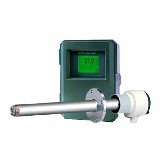
CO , SOx and NOx. ZR22S Separate type Explosion-proof Detector uses a high-reliability Zirconia sensor, and its heater assembly can be replaced on site. The detector is mounted, for example, on the wall of a flue and can measure the gases directly. -
Page 21: System 2
A “combustible gas detected” contact input turns off power to the heater. There’s also contact output from the converter that can be used to operate a purge gas valve to supply air to the sensor. Hazardous Area Non-hazardous Area ZR22S Separate type Explosion-proof ZR402G Converter Zirconia Oxygen Analyzer, Detector EXA ZR402G Signal... -
Page 22: Exaxt Zr > System Components
System configuration System Components System 1 System 2 ZR22S Separate type Explosion-proof Zirconia Oxygen Analyzers, Detector ZR402G Separate type Zirconia Oxygen Analyzer, Converter ZO21P High Temperature Probe Adapter for separate type Zirconia Oxygen Analyzer E7046EC, E7046EN Ejector Assembly for High Temperature... - Page 23 Blank Page...
-
Page 24: Specifications
The ZR22S is connected to a ZR402G or AV550G*1 that is mounted in a non-hazardous area. The ambient temperature is in the range -20 to + 60°C. The surface temperature of the ZR22S is not over the temperature class T2 (300°C)*2. - Page 25 Response of 90% within 5 seconds. (Measured after gas is introduced from calibration gas inlet and analog output starts changing.) Safety, EMC, and RoHS conformity standards of ZR22S and ZR402G Installation altitude based on IEC 61010: 2000 m or less...
- Page 26 <2. Specifications> Separate type Explosion-proof Detector and Related Equipment Separate type Explosion-proof detector ZR22S can be used in combination with the probe protector ZO21R (see Subsection 2.2.2). 2.2.1 ZR22S Separate type Explosion-proof Detector Flameproof Type ATEX Flameproof: ZR22S-A Applicable Standard: EN 60079-0: 2012+A11: 2013, EN 60079-1: 2014...
- Page 27 SUFFIX : Specified suffix code STYLE : Style code AMB. TEMP : Ambient temperature NO. : Serial No. and year of production* Yokogawa Electric Corporation : The manufacturer name Tokyo 180-8750 JAPAN : The manufacturer address* The country of origin. No. IECEx KEM 06.0006X...
- Page 28 Insertion length of 2.0 m: Approx. 19 kg (ANSI 150 4) Available Converter: ZR402G, AV550G CAUTION The ZR22S must be used in conjunction with a ZR402G or AV550G. If used with a converter other than a ZR402G or AV550G, the ZR22S does not operate as an explosion-proof equipment. IM 11M13A01-02E...
- Page 29 They shall provide a degree of ingress protection of at least IP66. When using ZR22S as CE marking compliance product, select -A (ATEX certified flameploof). “-Q” is the explosion-proof type of EAC with Pattern Approval for Russia. “-R” is the explosion-proof type of EAC for Kazakhstan and Belarus.
- Page 30 <2. Specifications> External Dimensions ZR22S Separate type Explosion-proof Zirconia Oxygen Analyzer, Detectors Unit : mm ±3 ±3 L (m) tolerance (mm) 0.15 ±4 ±5 ±7 ±8 ±3 ±3 ±10 Rc1/4 or 1/4 NPT (F) ±12 Reference gas inlet 2-M20 × 1.5 or 2-1/2 NPT (F)
-
Page 31: Zo21R Probe Protector
<2. Specifications> 2.2.2 ZO21R Probe Protector Used when sample gas flow velocity is approx. 10 m/sec or more and dust particles wears the detector in cases such as pulverized coal boiler of fluidized bed furnace (or burner) to protect the detector from wearing by dust particles. Insertion Length: 1.05, 1.55, 2.05 m. -
Page 32: Separate Type Explosion-Proof Detector For High Temperature And Related Equipment
<2. Specifications> Separate type Explosion-proof Detector for High Temperature and Related Equipment 2.3.1 ZR22S (0.15 m) Separate type Explosion-proof Detector for High Temperature Standard Specifications Construction: Water-resistant Probe length: 0.15 m Terminal box: Aluminum alloy Probe material: Probe material in contact with gas: 316 SS (JIS), 316L SS (JIS) (Probe),... -
Page 33: Zo21P High Temperature Probe Adapter
ZO21P High Temperature Probe Adapter Measuring O in the high temperature gases (exceeds 700°C) requires a explosion-proof detector ZR22S of 0.15 m length and a high temperature probe adapter. Sample gas temperature: 0 to 1400°C (when using SiC probe) 0 to 800°C (when using 310S SS probe) Sample gas pressure: -0.5 to +5 kPa. - Page 34 Rc1/2(Note2) JIS 5K 32 FF equivalent Gasket (Thickness 1.5) Ø60.5 ØA Flange <1> Approx. 48 Flange provided Detector (ZR22S) by customer Ø52 over Reference gas inlet Rc1/4 or 1/4 NPT 95±3 High temperature Probe SiC pipe Ø30 Pipe hole (2- M20, 2-1/2 NPT) Calibration gas inlet Rc1/4 or 1/4 NPT (Note 1) L = 0.5、0.6、0.7、0.8、0.9、1.0、1.5 (m)
-
Page 35: Zr402G Separate Type Converter
2-12 <2. Specifications> ZR402G Separate type Converter CAUTION Converter (Model ZR402G) must not be located in hazardous area. 2.4.1 Standard Specification The ZR402G Separate type Converter can be controlled by LCD touchscreen on the converter. Display: LCD display of size 320 by 240 dot with touchscreen. Output Signal: 4 to 20 mA DC, two points (maximum load resistance 550 Ω) Contact Output Signal: Four points (one is fail-safe, normally open) -
Page 36: Functions
2-13 <2. Specifications> 2.4.2 Functions Display Functions: Value Display; Displays values of the measured oxygen concentration, etc Graph Display; Displays trends of measured oxygen concentration Data Display; Displays various useful data for maintenance, such as cell temperature, reference junction temperature, maximum/minimum oxygen concentration, or the like Status Message;... - Page 37 2-14 <2. Specifications> Display and setting content: Measuring Related Items: Oxygen concentration (vol%O ), output current value (mA), air ratio, moisture quantity (in hot gases) (vol% H Display Items: Cell temperature (°C), thermocouple reference junction temperature (°C), maximum/minimum/average oxygen concentration (vol% O ), cell e.m.f.
- Page 38 2-15 <2. Specifications> Two points (voltage-free) Contact Input: The following functions are programmable for contact inputs: (1) Calibration gas pressure decrease alarm, (2) Range switching, (3) External calibration start, (4) Process alarm (if this signal is received, the heater power turns off), (5) Blow back start Contact capacity: Off-state leakage current;...
- Page 39 2-16 <2. Specifications> External Dimensions Unit: mm 1 to 6 (Panel Thickness) 2B mounting pipe 4 - Ø6 holes EXA ZR402G for Wall mounting 57.3 136.3 54.7 8-G1/2, *8-1/2NPT etc (Wiring connection) *: 1/2NPT with plug 24 14 ( for wall mounting) 4 - Ø6 holes 4-R8 to R10 4-C5 to C8...
-
Page 40: Za8F Flow Setting Unit And Zr40H Automatic Calibration Unit
Calibration Gas (zero gas, span gas) Consumption: Approx. 0.7 L/min (at calibration time only) Weight: Approx. 2.3 kg NOTE Use instrument air for span calibration gas, if no instrument air is available, contact YOKOGAWA. Model and Codes Model Suffix code Option code... - Page 41 2-18 <2. Specifications> External Dimensions Unit : mm ø6 Hole REFERENCE CHECK JIS 50A (60.5mm) REFERENCE SPAN ZERO mounting pipe 235.8 222.8 Calibration gas outlet Span gas inlet Reference gas outlet Zero gas inlet Piping connection port A CHECK SPAN ZERO Model Piping connection port A ZA8F-J*C...
-
Page 42: Zr40H Automatic Calibration Unit
2-19 <2. Specifications> 2.5.2 ZR40H Automatic Calibration Unit CAUTION Automatic Calibration Unit (Model ZR40H) must not be located in hazardous area. This automatic calibration unit is applied to supply specified flow of reference gas and calibration gas during automatic calibration to the detector in a system configuration (System 2). •... - Page 43 2-20 <2. Specifications> External Dimensions Unit: mm 2B pipe mounting example Wiring inlet ; 2-G1/2,Pg13.5,M20X1.5 or 1/2NPT(Female) (wiring inlet is at same position on rear) *1 with four ISO M6 screws can wall-mount 116.5 71.5 41.2 41.2 4 - Ø6.5 Connection port Flowmeter Needle valve Terminal box...
-
Page 44: Zo21S Standard Gas Unit
2-21 <2. Specifications> ZO21S Standard Gas Unit CAUTION Standard Gas Unit (Model ZO21S) must not be located in hazardous area. This is a handy unit to supply zero gas and span gas to the detector as calibration gas. It is used in combination with the detector only during calibration. -
Page 45: Other Equipments
2-22 <2. Specifications> Other Equipments 2.7.1 Ejector Assembly for High Temperature (E7046EC, E7046EN) This ejector assembly is used where pressure of sample gas for high temperature detector is negative. This ejector assembly consists of an ejector, a pressure gauge assembly and a needle valve. -
Page 46: Stop Valve (L9852Cb, G7016Xh)
2-23 <2. Specifications> Needle valve Pressure gauge Ejector Air source Graph 1 Graph 2 Po (kPa) Qa (l/min) P= 0.5 P (kPa) L (m) Pressure setting characteristics Air consumption characteristics Sample Gas Graph 3 Graph 4 Pg (kPa) (kPa) : Pressure setting Qg (l/min) (kPa) : Drive pressure (at the ejector entrance) -
Page 47: Check Valve (K9292Dn, K9292Ds)
2-24 <2. Specifications> Standard Specifications Material: 316 SS (JIS) Connection: Rc 1/4 or 1/4 FNPT Weight: Approx. 200 g Part No. Description L9852CB Joint: Rc 1/4, Material: 316 SS (JIS) G7016XH Joint: 1/4 FNPT, Material: 316 SS (JIS) Unit : mm Ø48 Analyzer L9852CB 2-Rc1/4... -
Page 48: Air Set
2-25 <2. Specifications> Standard Specifications Material: 304 SS (JIS) Connection: Rc1/4 or 1/4 FNPT Pressure: 150 kPaG or more and 350 kPaG or less Weight: Approx. 90 g Part No. Description K9292DN Joint: Rc 1/4, Material: 304 SS (JIS) K9292DS Joint: 1/4 FNPT, Material: 304 SS (JIS) K9292DN : Rc 1/4(A),R 1/4(B) Unit: mm K9292DS : 1/4 FNPT(A),1/4 NPT(Male)(B) -
Page 49: Cylinder Pressure Reducing Valve (G7013Xf, G7014Xf)
2-26 <2. Specifications> External Dimensions Unit : mm View A Panel cut dimensions Horizontal Vertical mounting mounting ø15 +0.5 2-ø2.2 2-ø6.5 2-ø6 screw depth 8 Panel (Horizontal mounting) Secondary pressure Panel (Vertical mounting) gauge Ø74 Secondary Primary G7003XF, G7004XF: Rc 1/4 K9473XK, K9473XG: 1/4 FNPT (with joint adapter) Approx. -
Page 50: Zr22A Heater Assembly
— Always-A *1 Suffix code of length should be selected as same as ZR22S installed. *2 Jig part no. is K9470BX to order as a parts after purchase. (Note) The heater is made of ceramic, do not drop or subject it to pressure stress. - Page 51 2-28 <2. Specifications> External Dimensions Jig for change Unit : mm (K9470BX) L ± 12 Model & Codes Weight (kg) ZR22A-015 Approx. 0.5 ZR22A-040 Approx. 0.8 ZR22A-070 Approx. 1.2 ZR22A-100 1152 Approx. 1.6 ZR22A-150 1652 Approx. 2.2 ZR22A-200 2152 Approx. 2.8 F02-18E.ai IM 11M13A01-02E...
- Page 52 2-29 <2. Specifications> IM 11M13A01-02E...
-
Page 53: Installation
The ZR22S is connected to a ZR402G or AV550G* that is mounted in a non-hazardous area. The ambient temperature is in the range -20 to +60°C. The surface temperature of the ZR22S is not over the temperature class T2 (300°C)* *1: Refer to IM 11M12D01-01E *2: The terminal box temperature does not exceed 150°C. -
Page 54: Installation Of General-Purpose Detector
• Take care not to generate mechanical sparking when accessing to the detector and peripheral devices in hazardous location Note 4: Maintenance and Repair • The detector modification or parts replacement by other than authorized representative of Yokogawa Electric Corporation is prohibited and will void the certification. IM 11M13A01-02E... -
Page 55: Fm Explosion-Proof Type
Special fastener Figure 3.2 Special fastener 3.1.3 FM Explosion-proof Type ZR22S-B Detector for use in hazardous locations: Note 1: Applicable Standard: FM3600 1998,FM3615 1989, FM3810 2005, ANSI/ NEMA 250 1991 Type of protection: Explosion-proof for Class I, Division 1, Groups B, C and D... -
Page 56: Csa Explosion-Proof Type
• Take care not to generate mechanical sparking when accessing to the detector and peripheral devices in hazardous location Note 4: Maintenance and Repair • The detector modification or parts replacement by other than authorized representative of Yokogawa Electric Corporation is prohibited and will void Factory Mutual Explosion-proof Approval. 3.1.4 CSA Explosion-proof Type... -
Page 57: Iecex Flameproof Type
• Take care not to generate mechanical sparking when accessing to the detector and peripheral devices in hazardous location Note 4: Maintenance and Repair • The detector modification or parts replacement by other than authorized representative of Yokogawa Electric Corporation is prohibited and will void Canadian Standards Explosion-proof Certification. 3.1.5 IECEx Flameproof Type... - Page 58 <3. Installation> Note 5: Cable Entry • The threaded type of cable entry is marked beside the cable entry according to the following markings. Threaded type : Marking M20 × 1.5 : 1/2 NPT : • In case of ANSI 1/2 NPT plug, ANSI hexagonal wrench should be applied to screw in.
-
Page 59: Probe Insertion Hole
<3. Installation> 3.1.6 Probe Insertion Hole Includes those analyzers equipped with a probe supporter and probe protector. When preparing the probe insertion hole, the following should be taken into consideration: CAUTION • The outside dimension of detector may vary depending on its options. Use a pipe that is large enough for the detector. -
Page 60: Installation Of Probe Protector (Zo21R)
F03-5E.ai Figure 3.7 Mounting of detector with a probe protector Installation of High Temperature Detector (Model ZR22S--015) 3.2.1 Installation Location This detector is used with the High Temperature Probe Adapter (Model ZO21P) when the temperature of sample gas exceeds 700°C, or when it is required due to maintenance spaces. -
Page 61: Usage Of High Temperature Probe Adapter (Model Zo21P)
When the surface temperature is not within the above range, the following measures can be taken to change the temperature. CAUTION When the surface temperature of ZR22S or ZO21P exceeds temperature class T2(300°C), this system shall not satisfy explosion-proof requirement for outside of the furnace. <When the surface temperature exceeds 300°C>... -
Page 62: Probe Insertion Hole
3.2.3 Probe Insertion Hole A high temperature detector consists of a ZR22S--015 Detector and ZO21P High Temperature Probe Adapter. When forming the probe insertion hole, the following should be taken into consideration: (1) If the probe is made of silicon carbide (SiC), the probe hole should be formed so that the probe is mounted vertically (within ±... -
Page 63: Mounting Of High Temperature Detector
3-11 <3. Installation> 3.2.4 Mounting of High Temperature Detector CAUTION • Ceramic (zirconia) is used in the sensor (cell) portion on the detector probe tip. Care should be taken not to drop the detector during installation. • The same applies to the high temperature probe adapter with a probe made of silicon carbide (SiC). -
Page 64: Installation Of Zr402G Converter
3-12 <3. Installation> Installation of ZR402G Converter CAUTION Converter (Model ZR402G) must not be located in hazardous area. 3.3.1 Installation Location The following should be taken into consideration when installing the converter: (1) Readability of the indicated values of oxygen concentration or messages on the converter display. - Page 65 3-13 <3. Installation> <Wall Mounting> (1) Drill mounting holes through the wall as shown in Figure 3.11. Unit: mm Four holes 6 mm in diameter for M5 screws 126.5 F03-10E.ai F03-9E.ai Figure 3.11 Mounting holes Figure 3.12 Wall Mounting (2) Mount the converter. Secure the converter on the wall using four screws. Note: For wall mounting, the bracket and bolts are not used.
-
Page 66: Installation Of Za8F Flow Setting Unit
3-14 <3. Installation> Installation of ZA8F Flow Setting Unit 3.4.1 Installation Location The following should be taken into consideration: (1) Easy access to the unit for checking and maintenance work. (2) Near to the detector or the converter (3) No corrosive gas. (4) An ambient temperature of not more than 55 °C and little changes of temperature. -
Page 67: Installation Of Zr40H Automatic Calibration Unit
3-15 <3. Installation> Installation of ZR40H Automatic Calibration Unit CAUTION Automatic Calibration Unit (Model ZR40H) must not be located in hazardous area. 3.5.1 Installation Location The following should be taken into consideration: (1) Easy access to the unit for checking and maintenance work. (2) Near to the detector or the converter (3) No corrosive gas. - Page 68 3-16 <3. Installation> <Wall Mounting> (1) Make a hole in the wall as illustrated in Figure 3.19. Unit : mm 4 - Ø6.5 hole, or M6 screw F03-17E.ai Figure 3.19 Mounting holes (2) Mount the automatic calibration unit. Remove the U-bolt from the automatic calibration unit and attach the unit on the wall with four screws.
-
Page 69: Insulation Resistance Test
8. After conducting all the tests, replace the jumper plate as it was. Insulation ZR402G Converter ZR22S Detector resistance tester crossover wiring CELL CELL CELL... - Page 70 Blank Page...
-
Page 71: Piping
Do not loosen or remove any Flame Arrestor of gas inlet/outlet during piping. The detector modification or parts replacement by other than authorized representative of Yokogawa Electric Corporation is prohibited and will void ATEX Certification, FM Approval, CSA Certification and IECEx Certification. -
Page 72: Piping For A System Using Flow Setting Unit For Manual Calibration
The piping for a system using flow setting units for manual calibration is shown in Figure 4.1. Hazardous Area Non-hazardous Area ZR402G Converter ZR22S Separate type Explosion-proof Zirconia Oxygen Analyzer, Detector EXA ZR402G Stop valve ~ 100 to 240 V AC... -
Page 73: Parts Required For Piping In A System Using Flow Setting Units For Manual Calibration
Calibration gas inlet Stop valve or check Recommended by YOKOGAWA detector valve (L9852CB or G7016XH) Provided by YOKOGAWA (K9292DN or K9292DS) Nipple * R1/4 or 1/4 NPT General parts Zero gas cylinder User´s scope Pressure reducing valve Recommended by YOKOGAWA... -
Page 74: Piping For The Calibration Gas Inlet
40°C. Mount a pressure reducing valve (specified by YOKOGAWA) on the cylinder. Mount a check valve or stop valve (specified by YOKOGAWA) on the nipple (found on the local market) at the calibration gas inlet of the detector as illustrated in Figure 4.2. - Page 75 <4. Piping> Pressure gauge Ejector Ejector assembly for Detector high temperature High temperature probe adapter F04-3E.ai Figure 4.3 Mounting the ejector assembly If the temperature of the sample gas is high and its pressure exceeds 0.49 kPa, the temperature of the sample gas at the detector may not be below 700°C. In such a case, connect a needle valve (found on the local market) through a nipple (also found on the local market) to the sample gas outlet (Rc1/2) of the probe adapter so that the sample gas exhaust volume is restricted.
-
Page 76: Piping For A System To Perform Automatic Calibration
The piping for a system to perform automatic calibration is shown in Figure 4.6. The piping is basically the same as that of a system using flow setting unit for manual calibration. Refer to Section 4.1. Hazardous Area Non-hazardous Area ZR22S Separate type Explosion-proof ZR402G Converter Zirconia Oxygen Analyzer, Detector EXA ZR402G Signal... -
Page 77: Parts Required For Piping In A System To Perform Automatic Calibration
(K9292DN or K9292DS) Nipple * R1/4 or 1/4 NPT General parts Zero gas cylinder User´s scope Pressure reducing valve Recommended by YOKOGAWA (G7013XF or G7014XF) Joint for tube connection R1/4 or 1/4 NPT General parts Reference gas inlet Air set... -
Page 78: Piping For The Calibration Gases
<4. Piping> 4.2.2 Piping for the Calibration Gases The piping for the calibration gases should be installed between the calibration gas cylinders (or instrument air source) and the detectors with the ZR40H automatic calibration unit. Figure 4.7 shows the ZR40H Automatic Calibration Unit piping diagram. Adjust secondary pressure of both the air set and the zero gas pressure reducing valve so that these two pressures are approximately the same. -
Page 79: Piping To The High Temperature Probe Adapter
• Blow pipe (to be prepared as illustrated in Figure 4.11.) • Two-way solenoid valve: “ Open “ when electric current is on. (Found on the local market) • Air set (Yokogawa recommended: G7003XF / K9473XK or G7004XF / K9473XG) IM 11M13A01-02E... - Page 80 4-10 <4. Piping> <Blow pipe manufacturing> Manufacture the blow pipe as illustrated in Figure 4.9, and mount it on the high temperature probe adapter. Unit : mm 4-Φ9 Blind flange of the high temperature probe adapter Rc1/4 Φ73 Welded Approximately 8 (O.D.) by 6 (I.D.) Stainless steel pipe F04-9E.ai Figure 4.9 Blow pipe Construction...
-
Page 81: Wiring
<5. Wiring> Wiring In this Chapter, the wiring necessary for connection to the EXAxt ZR Separate type Explosion- proof Zirconia Oxygen Analyzer is described. General CAUTION • NEVER supply current to the converter or any other device constituting a power circuit in combination with the converter, until all wiring is completed. -
Page 82: Terminals For The External Wiring In The Converter
<5. Wiring> WARNING Cables that withstand temperatures at least 80°C should be used for wiring. CAUTION • Select suitable cable O.D. to match the cable gland size. • Protective grounding should be connected in ways equivalent to JIS D style (Class 3) grounding (the grounding resistance is 100 Ω... -
Page 83: Wiring
(3) Analog output signal (4) Power and ground (5) Contact output (6) Operation of the solenoid valve of automatic calibration unit (7) Contact input ZR402G Separate type ZR22S Separate type Explosion-proof Zirconia Oxygen Analyzer, Detector Zirconia Oxygen Analyzer, Converter Analog Analog output 1... -
Page 84: Mounting Of Cable Gland
<5. Wiring> 5.1.3 Mounting of Cable Gland For each cable connection opening of the converter, mount a conduit that matches the thread size, or a cable gland. EXA ZR402G 8-G1/2, 8-1/2NPT or the like (Wiring connection) Ground terminal (M4) Adaptor for 1/2 NPT thread F05-3E.ai Figure 5.3 Cable gland mounting IM 11M13A01-02E... -
Page 85: Wiring For Detector Output
<5. Wiring> Wiring for Detector Output This wiring enables the converter to receive cell output from the detector, output from a thermocouple and a reference junction compensation signal. Install wires that allow for 10 Ω of loop resistance or less. Keep detector wiring away from power wiring. CAUTION Be sure to read Subsection 3.1.2 to 3.1.5 where the important information on writing is provided. -
Page 86: Connection To The Detector
<5. Wiring> 5.2.2 Connection to the Detector To connect cables to the detector, proceed as follows: (1) Mount conduits of the specified thread size or cable glands to the wiring connections of the detector. The detector may need to be removed in future for maintenance, so be sure to allow sufficient cable length. -
Page 87: Wiring For Power To Detector Heater
<5. Wiring> Wiring for Power to Detector Heater This wiring provides electric power from the converter to the heater for heating the sensor in the detector. CAUTION Refer to section 3.1. (1) Surface temperature of the detector terminal box: 75 °C or less Hazardous area Non-hazardous area Detector... -
Page 88: Connection To Converter
<5. Wiring> CAUTION • Before opening the detector cover, loosen the lock screw. If the screw is not loosened first, the screw will damage the cover, and the terminal box will require replacement. When opening and closing the cover, remove any sand particles or dust to avoid gouging the thread. -
Page 89: Wiring For Analog Output
FG terminal of the converter. (2) Be sure to connect “+” and “-” polarities correctly. Power and Grounding Wiring This wiring supplies power to the converter and grounds the converter/detector. ZR402G ZR22S Converter Detector L N G Grounding to the ground terminal... -
Page 90: Grounding Wiring
5-10 <5. Wiring> 5.5.2 Grounding Wiring The ground wiring of the detector should be connected to the ground terminal of the detector case. The ground wiring of the converter should be connected to either the ground terminal of the converter case or the protective ground terminal in the equipment. The grounding terminals of the detector are of size of M4 (inside) and M5 (outside), and the grounding terminals of the converter are of size M4. -
Page 91: Cable Specifications
5-11 <5. Wiring> 5.6.2 Wiring Procedure (1) M4 screws are used for the terminals of the converter. Each wire in the cable should be terminated corresponding to crimp-on terminals. (2) The capacities of the contact output relay are 30V DC 3 A, 250V AC 3 A. Connect a load (e.g. -
Page 92: Cable Specifications
5-12 <5. Wiring> 5.7.2 Wiring Procedure M4 screws are used for the terminals of the converter. Each wire in the cable should be terminated corresponding to crimp-on terminals. M4 screws are used for the terminals of the solenoid valve as well. ZR402G ZR40H Automatic Converter... -
Page 93: Components And Their Functions
<6. Components and Their Functions> Components and Their Functions In this Chapter, the names and functions of components are described for the major equipment of the EXAxt ZR Separate type Explosion-proof Zirconia Oxygen Analyzer. ZR22S Detector 6.1.1 General-purpose Explosion-proof Detector (except for ZR22S--015) Flange Used to mount the detector. -
Page 94: High Temperature Detector (Zr22S--015)
<6. Components and Their Functions> 6.1.2 High Temperature Detector (ZR22S--015) Sample gas outlet When a sample gas pressure is negative, connect the auxiliary ejector assembly. When the sample gas is high temperature and high pressure, Separate type and does not fall below 700°C, High Temperature Detector (ZR22S--015) -
Page 95: Zr402G Converter
<6. Components and Their Functions> ZR402G Converter Complete Operation Display Touch Screen Display ■ Interactive operations along with operation display. ■ ● Example of basic display A variety of display modes - enabling you to select the operation mode freely. ■... -
Page 96: Touchpanel Switch Operations
<6. Components and Their Functions> Touchpanel Switch Operations 6.3.1 Basic Panel and Switch The converter uses a touchpanel switch which can be operated by just touching the panel display. Figure 6.4 shows the Basic panel display. The switches that appear in the switch display area vary depending on the panel display, allowing all switch operations. -
Page 97: Display Configuration (For Oxygen Analyzer)
<6. Components and Their Functions> 6.3.2 Display Configuration (for Oxygen Analyzer) Figure 6.5 shows the configuration. A password the displays positioned below enables display “Execution/Setup” to be protected. If a password has not been set, press the [Enter] key to proceed to the next panel display. -
Page 98: Display Functions
<6. Components and Their Functions> 6.3.3 Display Functions Individual panel displays in the display configuration provide the following functions: (1) Basic panel display: Displays the values measured in three selected items. (see Section 7.9, “Setting Display Item”). (2) Execution/Setup display: Selects the calibration, maintenance and setup items. (3) Detailed-data display: This allows you to view such detailed data as the cell electromotive force and cell temperature. - Page 99 <6. Components and Their Functions> Operation Display Press the [ABC] key once. Press and hold the [ABC] key. AB _ Release the [ABC] key when the character B appears in the cursor position. ABC _ Enter the character C in the same manner as above.
-
Page 100: Za8F Flow Setting Unit, Zr40H Automatic Calibration Unit
<6. Components and Their Functions> ZA8F Flow Setting Unit, ZR40H Automatic Calibration Unit Reference gas flow setting valve Span gas flow setting valve Zero gas flow setting valve Flowmeter for reference gas Flowmeter for calibration gas F06-8E.ai Figure 6.8 ZA8F Flow Setting Unit Flowmeter for calibration gas Flowmeter for... -
Page 101: Startup
<7. Startup> Startup The following describes the minimum operating requirements — from supplying power to the converter to analog output confirmation to manual calibration. System tuning by the HART communicator, refer to IM11M12A01-51E “ HART Communication Protocol ”. Startup Procedure The startup procedure is as follows: CAUTION If you connect Model ZO21D* detectors, then you need to change the detector parameters. -
Page 102: Checking Valve Setup
<7. Startup> Checking Valve Setup Set up valves and associated components used in the analyzer system as follows: (1) If a stop valve is used in the detector’s calibration gas inlet, fully close this valve. (2) If instrument air is used as the reference gas, adjust the air-set secondary pressure so that an air pressure equals sample gas pressure plus approx. -
Page 103: Confirmation Of Converter Type Setting
<7. Startup> Confirmation of Converter Type Setting This converter can be used for both the Oxygen Analyzer and the Humidity Analyzer. Before setting the operating data, be sure to check that the desired converter model has been set. Note that if the converter type setting is changed, the operating data that have been set are then initialized and the default settings remain. -
Page 104: Confirmation Of Detector Type Setting
<7. Startup> Confirmation of Detector Type Setting Check that the detector in Figure 7.6 is the one for this equipment. WARNING ● If this converter is to be used in conjunction with the ZO21D*, the power requirements are limited to 115 V AC or less, 50 or 60 Hz (it cannot be used with a 125 V or greater, or in the EEC). -
Page 105: Setting Display Item
<7. Startup> Setting Display Item This section briefly describes the display item settings shown in Figure 7.9, “Basic Panel Display.” Tag: 21.0 Primary value Secondary value 17.43mA -Output1 17.43mA -Output2 Tertiary value F07-10E.ai Figure 7.10 Basic Panel Display (1) Press the [Setup] key in the Basic panel display to display the Execution/Setup display. Then select the “Maintenance”... -
Page 106: Checking Current Loop
<7. Startup> Table 7.1 Display Items Secondary and Item Primary value Display tertiary values Oxygen concentration Oxygen concentration during measurement Air ratio Current computed air ratio Moisture quantity Moisture quantity (%H O) in the exhaust gas Oxygen concentration with the equipment set for oxygen Output 1 item ... -
Page 107: Checking Contact I/O
<7. Startup> (3) At the time of entering the numeric-data entry display, the output current will change to 4 mA (default value). If the desired current is entered, the corresponding output will be provided. mA - output loop check mA - output 1 mA - output 2 ... -
Page 108: Checking Calibration Contact Outputs
<7. Startup> 7.11.2 Checking Calibration Contact Outputs The calibration contacts are used for solenoid valve drive signals for the ZR40H Automatic Calibration Unit. When using the ZR40H Automatic Calibration Unit, use the calibration contact output to check that the wiring connections have been properly completed and check equipment operation. -
Page 109: Calibration
<7. Startup> 7.12 Calibration To calibrate this instrument, the procedure is to measure zero gas and span gas and set the instrument to read the known concentrations. The procedure for both zero and span calibration, or for either zero or span calibration, can be performed manually from the touch display, or can be performed semi-automatically using contact signal inputs to start calibration, (allowing preset calibration and stabilization times), or it can be performed automatically at preset intervals. -
Page 110: Manual Calibration
7-10 <7. Startup> (2) Span gas concentration With “Span gas conc” selected in the Calibration setup display, display the Numeric - data Entry display and enter an oxygen concentration value for the span gas calibration; If instrument air is used, enter 02100 for a 21 vol%O value. - Page 111 7-11 <7. Startup> (3) Follow the display message in Figure 7.23 to turn on span gas flow. Open the span gas flow valve for the Flow Setting Unit by loosening the valve lock nut and slowly turning the valve shaft counterclockwise to flow the span gas at 600 ± 60 ml/min. Use the calibration gas flowmeter to check the flow.
- Page 112 7-12 <7. Startup> (7) Follow the instructions in the display as in Figure 7.27 to turn on the zero gas flow. To do this, open the zero gas flow valve for the Flow Setting Unit and adjust that valve to obtain a flow of 600 ±...
-
Page 113: Detailed Data Setting
<8. Detailed Data Setting> Detailed Data Setting Current Output Setting This section describes setting of the analog output range. 8.1.1 Setting Minimum Current (4 mA) and Maximum Current (20 mA) To set the minimum and maximum currents, proceed as follows: (1) Select the “Commissioning”... -
Page 114: Setting Output Smoothing Coefficient
<8. Detailed Data Setting> Setting example 2 If the range minimum (corresponding to 4 mA output) is set to 75 vol%O then range maximum (corresponding to 20 mA output) must be at least 75x1.3=98 vol%O (rounding decimal part up). Ranges over which oxygen concentrations can be set Outside ranges Minimum oxygen concentration, vol%O... -
Page 115: Output Hold Setting
<8. Detailed Data Setting> Output Hold Setting The “output hold” functions hold an analog output signal at a preset value during the equipment’s warm-up time or calibration or if an error arises. Outputs 1 and 2 can not be set individually. Table 8.2 shows the analog outputs that can be retained and the individual states. -
Page 116: Preference Order Of Output Hold Value
<8. Detailed Data Setting> 8.2.2 Preference Order of Output Hold Value The output hold value takes the following preference order: On error occurrence Under calibration or during blow back Preference order (high) Under maintenance During warm-up Siki08-1E.ai For example, if the output current is set to 4 mA during maintenance, and no output-hold output for during calibration is preset, the output is held at 4 mA during the maintenance display. -
Page 117: Default Values
<8. Detailed Data Setting> 8.2.4 Default Values When the analyzer is delivered, or if data are initialized, output hold is the default as shown in Table 8.3. Table 8.3 Output Hold Default Values Status Output hold setting Preset value During warm-up 4 mA 4 mA Under maintenance... -
Page 118: Oxygen Concentration Alarms Setting
<8. Detailed Data Setting> Oxygen Concentration Alarms Setting The analyzer enables the setting of four alarms — high-high, high, low, and low-low alarms — depending upon the oxygen concentration. The following section sets out the alarm operations and setting procedures. 8.3.1 Setting the Alarm Values (1) High-high and high alarm values... -
Page 119: Alarm Setting Procedure
<8. Detailed Data Setting> In the example in Figure 8.3, the high limit alarm point is set to 7.5 vol%O , the delay time is set to five seconds, and hysteresis is set to 2 vol%O Alarm output actions in each section in this figure are as follows: A. -
Page 120: Default Values
<8. Detailed Data Setting> Oxygen alarms Alarms setup High High alarm: OFF Parameter: Oxygen Set value: 1 0 0 . 0 % O Hysteresis: 0.1%O High alarm: Contact delay: Set value: 1 0 0 . 0 % O ... -
Page 121: Setting Procedure
<8. Detailed Data Setting> 8.4.2 Setting Procedure To set the contact output, follow these steps. (1) Press the [Setup] key in the Basic panel display to display the Execution/Setup display. (2) Select the “Commissioning” in the Execution/Setup display. The Commissioning display then appears. - Page 122 8-10 <8. Detailed Data Setting> Table 8.6 Contact Output Settings Item to be selected Brief description High-high limit alarm If “High-High alarm ON” is selected, contact output occurs when the high-high limit is issued. To do this, it is required, in Alarms setup, that the high-high alarm be set on beforehand (see Section 8.3).
-
Page 123: Default Values
8-11 <8. Detailed Data Setting> 8.4.3 Default Values When the analyzer is delivered, or if data are initialized, alarm and other setting defaults are as shown in Table 8.7. Table 8.7 Contact Output Default Settings Item to be selected Output Output Output Output... -
Page 124: Contact Input Setting
8-12 <8. Detailed Data Setting> Contact Input Setting 8.5.1 Contact Input Functions The converter “Input contacts” execute set functions by accepting a remote dry-contact (“voltage- free contact”) signal. Table 8.8 shows the functions executed by a remote contact signal. Table 8.8 Contact Input Functions Item Function Calibration gas pressure low... -
Page 125: Setting Procedure
8-13 <8. Detailed Data Setting> 8.5.2 Setting Procedure This setting example shows how to set “When Input contact 1 Open, Start Semi_Auto Calibration”. Refer to Section 7.11.3. 1) From the Basic panel display touch [Setup] key, and the Execution/Setup display appears. 2) Select “Commissioning”... -
Page 126: Other Settings
8-14 <8. Detailed Data Setting> Other Settings 8.6.1 Setting the Date-and-Time The following describes how to set the date-and-time. Automatic calibration or blow back works following this setting. Proceed as follows: 1) If you touch the [Setup] key in the Basic panel display, the Execution/Setup display appears. 2) Select the “Commissioning”... -
Page 127: Setting Fuels
8-15 <8. Detailed Data Setting> Averaging Set period over which average is calculated: Set period over which maximum and minimum is stored: 2 4 h Enter F08-14E.ai Figure 8.14 Setting Average Value Calculation Periods and Maximum and Minimum Value Monitoring Periods Default Values “Set period over which average is calculated”... - Page 128 8-16 <8. Detailed Data Setting> For liquid fuel Amount of water vapor in exhaust gas (Gw) = (1/100) {1.24 (9h + w)} (m /kg) Theoretical amount of air (Ao) = 12.38 x (Hl/10000) – 1.36 (m /kg) Low calorific power = Hl X value = (3.37 / 10000) x Hx –...
- Page 129 8-17 <8. Detailed Data Setting> 0.046 0.044 0.042 0.040 0.038 0.036 0.034 0.032 0.030 0.028 Wet-bulb 0.026 Absolute temperature, °C humidity, kg/kg 0.024 0.022 0.020 0.018 0.016 0.014 0.012 0.010 0.008 0.006 0.004 0.002 0.000 12 14 16 18 20 22 24 26 28 30 32 34 36 38 40 Dry-bulb temperature, °C...
- Page 130 8-18 <8. Detailed Data Setting> Table 8.9 Fuel Data • For liquid fuel Fuel Theoretical Chemical component Calorific Amount of combustion Specific properties amount (weight percentage) power kJ/kg gas m weight of air for value combustion Type kg/l Higher Lower O SO Total content...
- Page 131 8-19 <8. Detailed Data Setting> Procedure To make a fuel setting, follow these steps: (1) Press the [Setup] key in the Basic panel display to display the Execution/Setup display. (2) Select the “Commissioning” in the Execution/Setup display. The Commissioning display then appears.
-
Page 132: Setting Purging
8-20 <8. Detailed Data Setting> 8.6.4 Setting Purging Purging is to remove condensed water in the calibration gas pipe by supplying a span calibration gas for a given length of time before warm-up of the detector. This prevents cell breakage during calibration due to condensed water in the pipe. -
Page 133: Setting Passwords
8-21 <8. Detailed Data Setting> 8.6.5 Setting Passwords Unauthorized access to lower level menu displays from the Execution/Setup display can be protected by passwords. You can set separate passwords for Calibration, Blow back, and Maintenance and for Commissioning Proceed as follows: 1) From the Basic panel display touch the [Setup] key, and the Execution/Setup display appears. - Page 134 Blank Page...
-
Page 135: Calibration
<9. Calibration> Calibration Calibration Briefs 9.1.1 Principle of Measurement This section sets forth the principles of measurement with a zirconia oxygen analyzer before detailing calibration. A solid electrolyte such as zirconia allows the conductivity of oxygen ions at high temperatures. Therefore, when a zirconia-plated element with platinum electrodes on both sides is heated up in contact with gases having different oxygen partial pressures on each side, the element shows the action of the concentration cell. -
Page 136: Calibration Gas
<9. Calibration> 0.51 vol% O ,81.92mV(Zero origin of calibration) Cell voltage (mV) 21.0 vol% O , 0mV (Span origin of calibration) 21.0 Oxygen concentration (vol % O F09-1E.ai Figure 9.1 Oxygen concentration in a Sample Gas vs Cell Voltage (21 vol%O Equivalent) The measurement principles of a zirconia oxygen analyzer have been described above. -
Page 137: Compensation
<9. Calibration> 9.1.3 Compensation The deviation of a measured value from the theoretical cell electromotive force is checked by the method in Figure 9.2 or 9.3. Figure 9.2 shows a two-point calibration using two gases: zero and span. Cell electromotive forces for a span gas with an oxygen concentration p1 and a zero gas with an oxygen concentration p2 are measured while determining the calibration curve passing between these two points. -
Page 138: Characteristic Data From A Sensor Measured During Calibration
<9. Calibration> 9.1.4 Characteristic Data from a Sensor Measured During Calibration During calibration, calibration data and sensor status data (listed below) are acquired. However, if the calibration is not properly conducted (an error occurs in automatic or semi- automatic calibration), these data are not collected in the current calibration. These data can be observed by selecting the [Detailed-data] key from the Basic panel display. -
Page 139: Calibration Procedures
<9. Calibration> Calibration Procedures NOTE Calibration should be made under normal operating conditions (if the probe is connected to a furnace, the analyzer will undergo calibration under the operating conditions of the furnace). To make a precise calibration, conduct both zero and span calibrations. 9.2.1 Calibration Setting The following sets forth the required calibration settings:... - Page 140 <9. Calibration> Calibration Procedure Select both span and zero calibrations or span calibration only or zero calibration only. Usually select span and zero calibrations. Select “Points” from the Calibration setup display and then you can select “Both,” “Span” or “Zero” (see Figure 9.5). Calibration setup Calibration setup ...
- Page 141 <9. Calibration> Setting Calibration Time • When the calibration mode is in manual: First set the “Hold time” (output stabilization time). This indicates the time required from the end of calibration to entering a measurement again. This time, after calibration, the sample gas enters the sensor to set the time until the output returns to normal.
-
Page 142: Default Values
<9. Calibration> NOTE When setting calibration timing requirements, bear the following precautions in mind: (1) If the calibration interval is shorter than the sum of hold (output stabilization) time plus calibration time, the second calibration start time will conflict with the first calibration. In such a case, the second calibration will not be conducted. -
Page 143: Calibration
<9. Calibration> 9.2.3 Calibration NOTE 1) Perform calibration under normal working conditions (e.g. continuous operation with sensor mounted on furnace). 2) Perform both Span and Zero calibration for best resultant accuracy. 3) When instrument air is used for the span calibration, remove the moisture from the instrument air at a dew-point temperature of -20°C and also remove any oily mist and dust from that air. - Page 144 9-10 <9. Calibration> To start calibration using a contact input, follow these steps: (1) Make sure that Calibration start has been selected in the “Input contacts” display (see Section 8.5, earlier in this manual). (2) Apply an input contact to start calibration. To stop calibration midway, follow these steps: (1) Press the [Reject] key.
-
Page 145: Other Functions
10-1 <10. Other Functions> Other Functions 10.1 Detailed-data Display Press the [Detailed-data] key on the Basic panel display to view the detailed operation data as shown in Figure 10.1. Pressing the [▼] or [▲] key, you can advance the page or go back to your desired page. •... -
Page 146: Thermocouple Voltage
10-2 <10. Other Functions> 10.1.2 Thermocouple Voltage The cell temperature is measured with a Type K (chromel-alumel) thermocouple. The thermocouple cold junction is located in the detector terminal box. The cell temperature and the thermocouple voltage (including the voltage corresponding to the cold junction temperature) are displayed. -
Page 147: Cell Response Time
10-3 <10. Other Functions> 10.1.7 Cell Response Time The cell’s response time is obtained in the procedure shown in Figure 10.3. If only either a zero or span calibration has been carried out, the response time will not be measured just as it will not be measured in manual calibration. -
Page 148: C. J. Temperature
10-4 <10. Other Functions> 10.1.10 C. J. Temperature This indicates the detector terminal box temperature, which compensates for the cold junction temperature for a thermocouple measuring the cell temperature. When the ZR22 Detector is used, the maximum C. J. temperature will be 150°C. If the terminal box temperature exceeds this, take measures to shield the terminal box from heat radiation. -
Page 149: Trend Graph
10-5 <10. Other Functions> 10.2 Trend Graph Press the [Graph display] key in the Basic panel display to switch to the graph display. This will help grasp the measured-value trend. Touching anywhere on the graph display will return to the Basic panel display. To set the Trend graph display, follow the steps in Subsection 10.2.1. -
Page 150: Setting Upper And Lower Limit Values On Graph
10-6 <10. Other Functions> Preset upper limit 25.0 %O 10 min./div Time per division, calculated by the set sampling interval 0.0 %O Preset lower limit 12.3 %O Currently measured value 60 data Sampling period F10-5E.ai Figure 10.5 Plotting Graph for Sampling Interval 10.2.3 Setting Upper and Lower Limit Values on Graph Set upper and lower limit values on the graph in the following procedure:... -
Page 151: Other Display-Related Functions
10-7 <10. Other Functions> 10.3 Other Display-related Functions 10.3.1 Auto-Return Time On the Execution/Setup display or lower level menu displays, if no keys are touched for a preset time, the Auto return time, then the display will automatically revert to the Basic panel display. The “Auto return time”... -
Page 152: Blow Back
10-8 <10. Other Functions> 10.4 Blow Back This section explains the parameter settings for performing blow back. 10.4.1 Mode of Blow back There are three modes of blow back operation: no function, semi-automatic, and automatic. Blow back is not performed when the mode is set to “No function”. In “Semi_Auto” mode, blow back can be started by key operation on the display or by a contact input signal, and then sequentially performed at a preset blow back time and hold time. -
Page 153: Setting Output Hold Time And Blow Back Time
10-9 <10. Other Functions> 10.4.3 Setting Output Hold Time and Blow back Time If the blow back mode is in “No function”, the output “Hold time” and “Blow back time” are not displayed. If you select “Hold time”, the numeric-data entry display appears. Enter the desired “Hold time”... -
Page 154: Default Setting
10-10 <10. Other Functions> 10.4.5 Default Setting When the analyzer is delivered, or if data are initialized, the blow back settings are by default, as shown in Table 10.4. Table 10.4 Blow back Default Setting Item Default setting Mode No function (“invalid”) Hold time 10 minutes, 00 seconds Blow back time... - Page 155 10-11 <10. Other Functions> Table 10.5 Initialization Items and Default Values Item Initialization Parameter Default setting Type of equipment Not initialized Equipment Detector ZR22 selection Sample gas Wet gas 1st display item Oxygen concentration 2nd display item Current output 1 Display item 3rd display item Current output 2...
- Page 156 10-12 <10. Other Functions> Item Initialization Parameter Default setting Oxygen Parameter concentration Alarm setting Hysteresis 0.1 vol%O Delayed action of alarm contact 3 seconds High-high alarm Alarm value of High-high alarm 100 vol%O Alarm data High limit alarm 100 vol%O Alarm value of High limit alarm Alarm set value Low limit alarm...
-
Page 157: Reset
10-13 <10. Other Functions> Item Initialization Parameter Default setting Average-value calculation One hour Average value/ Intervals over which max. and min. 24 hours Maximum and minimum values values are monitored Amount of water vapor in exhaust gas 0.00 m /kg (m Other data Theoretical amount of air 1.00 m... -
Page 158: Handling Of The Zo21S Standard Gas Unit
10-14 <10. Other Functions> 10.7 Handling of the ZO21S Standard Gas Unit The following describes how to flow zero and span gases using the ZO21S Standard Gas Unit. Operate the ZO21S Standard Gas Unit, according to the procedures that follow. 10.7.1 Standard Gas Unit Component Identification Carrying case... -
Page 159: Installing Gas Cylinders
10-15 <10. Other Functions> 10.7.2 Installing Gas Cylinders Each ZO21S Standard Gas Unit comes with six zero gas cylinders including a spare. Each gas cylinder contains 7-liters of gas with a 0.95 to 1.0 vol%O (concentration varies with each cylinder) and nitrogen, at a pressure of 700 kPaG (at 35°C). The operating details and handling precautions are also printed on the product. - Page 160 10-16 <10. Other Functions> <Flow of span gas (air)> The standard gas unit is used only when manual calibration is employed. Therefore, the timing for flowing span gas (air) is included in the manual calibration procedure described in Subsection 10.7.2. For operation of the converter, see Section 7.12, earlier in this manual. (1) When the message “Open span gas valve.”...
- Page 161 10-17 <10. Other Functions> Manual calibration Manual calibration Open zero gas valve. Zero calibration Set flow zero gas to Close the zero gas valve. 600ml/min. Valve opened Span calibration Cancel calibration End Enter Enter F10-17E.ai F10-18E.ai Figure 10.17 Manual Calibration Display Figure 10.18 Zero gas Calibration Complete (in Manual Calibration Display) NOTE...
-
Page 162: Methods Of Operating Valves In The Za8F Flow Setting Unit
10-18 <10. Other Functions> 10.8 Methods of Operating Valves in the ZA8F Flow Setting Unit The ZA8F Flow Setting Unit is used as a calibration device for a system conforming to System 1. Calibration in such a system is to be manually operated. So, you have to operate the valve of the Flow Setting Unit each time calibration is made (starting and stopping the calibration gas flow and adjusting the flow rate). -
Page 163: Operation After Calibration
10-19 <10. Other Functions> Manual calibration Open zero gas valve. Set flow zero gas to 600ml/min. Valve opened Cancel calibration Enter F10-19E.ai Figure 10.19 Manual Calibration Display (2) Adjust the flow rate and select “Valve opened” in the Manual calibration display. Check the Trend graph display to see that the measured value is stabilized. - Page 164 Blank Page...
-
Page 165: Inspection And Maintenance
When checking the detector, carefully observe the following: • The instrument modification or parts replacement by other than authorized representation of Yokogawa Electric Corporation is prohibited and will void ATEX flameproof Certification, Factory Mutual Explosion-proof approval and Canadian Standards Explosion-proof Certification. -
Page 166: Inspection And Maintenance Of The Detector
11-2 <11. Inspection and Maintenance> 11.1 Inspection and Maintenance of the Detector 11.1.1 Cleaning the Calibration Gas Tube The calibration gas, supplied through the calibration gas inlet of the terminal box into the detector, flows through the tube and comes out at the tip of the probe. The tube might become clogged with dust from the sample gas. - Page 167 11-3 <11. Inspection and Maintenance> CAUTION • If the sensor assembly is to be replaced, allow enough time for the detector to cool down from its high temperature. Otherwise, you may get burned. • If the cell assembly is to be replaced, be sure to replace the metal O-ring and the contact together.
- Page 168 11-4 <11. Inspection and Maintenance> 1. Identifying parts to be replaced In order not to lose or damage disassembled parts, identify the parts to be replaced from among all the parts in the sensor assembly. Normally, replace the sensor, metal O-ring and contact together at the same time.
-
Page 169: Replacement Of The Heater Unit (Assembly)
11-5 <11. Inspection and Maintenance> 11.1.3 Replacement of the Heater Unit (Assembly) This Subsection describes the replacement procedure for the heater unit. The sensor or ceramic heater-furnace core internal structure is subject to fracturing, so do NOT subject it to strong vibrations or shock. Additionally, the heater unit reaches high temperatures and is subjected to high voltages. - Page 170 11-6 <11. Inspection and Maintenance> TC + TC - CELL + View A - A CELL H T R F11-4E.ai Figure 11.4 Exploded View of Detector IM 11M13A01-02E...
- Page 171 11-7 <11. Inspection and Maintenance> Replacement of heater strut assembly Refer to Figure 11.4 as an aid in the following discussion. Remove the U-shaped pipe support , the U-shaped pipe , the Filter and the Sensor (Cell) according to Subsection 11.1.2 Replacing the Sensor Assembly. Open the terminal box and remove the three terminal connections –...
-
Page 172: Replacement Of Flame Arrestor Assembly
If the flame arrestor assembly is clogged with dust, replace it with new one or wash it. In case of the ATEX flameproof model (MS Code: ZR22S-A-...) or IECEx flameproof model (MS Code: ZR22S-D-...), the flame arrestor assembly... -
Page 173: Cleaning The High Temperature Probe Adapter
11-9 <11. Inspection and Maintenance> 11.1.6 Cleaning the High Temperature Probe Adapter CAUTION • Do NOT subject the probe of the High Temperature Probe Adapter (ZO21P) to shock. This probe uses silicon carbide (SiC) which may become damaged if it is subjected to a strong shock or thermal shock. -
Page 174: Inspection And Maintenance Of The Converter
11-10 <11. Inspection and Maintenance> 11.2 Inspection and Maintenance of the Converter The converter does not require routine inspection and maintenance. If the converter does not work properly, in most cases it probably comes from problems or other causes. A dirty touchpanel should be wiped off with a soft dry cloth. 11.2.1 Replacing Fuses The converter incorporates a fuse, as indicated in Figure 11.6. -
Page 175: Cleaning
11-11 <11. Inspection and Maintenance> To replace the fuse, follow these steps: (1) Turn off the power to the converter for safe replacement. (2) Remove the fuse from its holder. With the appropriate flat-blade screwdriver that just fits the holder cap slot (Figure 11.7), turn the fuse holder cap 90° counterclockwise. By doing so, you can remove the fuse together with the cap. -
Page 176: Replacing Flowmeter In Zr40H Automatic Calibration Unit
11-12 <11. Inspection and Maintenance> 11.3 Replacing Flowmeter in ZR40H Automatic Calibration Unit (1) Remove piping and wiring, and remove the ZR40H from the 2B pipe or wall mounting. (2) Remove four M6 bolts between brackets and remove piping extension (3) Remove bolts holding flowmeter, and replace it. -
Page 177: Troubleshooting
12-1 <12. Troubleshooting> Troubleshooting This chapter describes errors and alarms detected by the self-diagnostic function of the converter. It also explains inspections and remedies when other problems occur. 12.1 Displays and Remedies When Errors Occur 12.1.1 Error Types An error occurs when an abnormality is detected in the detector or the converter, e.g., in the cell (sensor), detector heater, or internal circuits of the converter. -
Page 178: Remedies When An Error Occurs
Is an error indicated assembly and temporarily The analyzer operates normally. on the display? place the analyzer in the operating status. See Subsection 11.1.2 A failure in the detector or End. Carry out calibration. the converter is suspected. Contact Yokogawa. F12E.ai IM 11M13A01-02E... - Page 179 Check for wiring problems such as the following: 1) Heater terminals shorted. 2) Heater terminal(s) shorted to ground. 3) Heater terminals shorted to power supply. If the internal fuse blows, this cannot be replaced by the user. Contact your Yokogawa service representative. IM 11M13A01-02E...
- Page 180 Check whether or not there is a failure in the power supply system or whether the converter and detector are securely grounded. If the error occurs again after restarting, a failure in the electrical circuits is suspected. Consult the service personnel at Yokogawa Electric Corporation. IM 11M13A01-02E...
-
Page 181: Displays And Remedies When Alarms Are Generated
12-5 <12. Troubleshooting> 12.2 Displays and Remedies When Alarms are Generated 12.2.1 Alarm Types When an alarm is generated, the alarm indication blinks in the display to notify of the alarm (Figure 12.3). Pressing the alarm indication displays a description of the alarm. Alarms include those shown in Table 12.2. -
Page 182: Remedies When Alarms Are Generated
12-6 <12. Troubleshooting> 12.2.2 Remedies When Alarms are Generated Alarm 1: Oxygen Concentration Alarm This alarm is generated when a measured value exceeds an alarm set point or falls below it. For details on the oxygen concentration alarm, see Section 8.3, Oxygen Concentration Alarms Setting, in the chapter on operation. - Page 183 12-7 <12. Troubleshooting> (4) Check whether the deterioration of or damage to the sensor assembly that caused the alarm has occurred suddenly during the current calibration in the following procedure: a. Call up the Detailed-data Display. b. Use the [Page Scroll] key to check Calibration data (Figure 12.6). The span and zero correction ratios of the last ten calibration can be checked here.
- Page 184 12-8 <12. Troubleshooting> Alarm 7: Span Calibration Coefficient (Correction Ratio) Alarm In automatic or semi-automatic calibration, this alarm is generated when the span correction ratio is out of the range of 0±18% (refer to Subsection 9.1.3, Compensation). The following are suspected as the cause: (1) The oxygen concentration of the span gas does not agree with the value of the span gas set in Calibration setup.
- Page 185 Also, check that the resistance of the wiring between the converter and detector is 10 Ω or less. (4) If there is no failure in the wiring, the electrical circuits inside the converter may possibly fail. Contact the service personnel at Yokogawa Electric Corporation. IM 11M13A01-02E...
- Page 186 Also check that the wiring resistance between the converter and the detector is 10 Ω or less. (4) If there is no failure in the wiring, the electrical circuits inside the converter may possibly fail. Contact the service personnel at Yokogawa. Alarm 13: Battery Low Alarm An internal battery is used as backup for the clock.
-
Page 187: Countermeasures When Measured Value Shows Error
12-11 <12. Troubleshooting> 12.3 Countermeasures When Measured Value Shows Error The causes that the measured value shows an abnormal value is not always due to instrument failures. There are rather many cases where the causes are those that sample gas itself is in abnormal state or external causes exist, which disturb the instrument operation. - Page 188 12-12 <12. Troubleshooting> 12.3.2 Measured Value Lower Than True Value <Causes and Countermeasures> (1) The sample gas pressure becomes lower. Where an increment of the measured value due to pressure change cannot be neglected, take measures referring to Subsection 12.3.1 (1). (2) Moisture content in a reference gas changes (decreases) greatly.
- Page 189 Cal. Gas Tube Assembly K9470ZL Cal. Gas Tube Assembly for Option code "/C" CMPL 11M13A01-02E All Rights Reserved, Copyright © 2005, Yokogawa Electric Corporation. Subject to change without notice. 1st Edition : Apr. 2005 (YK) 4th Edition : Feb. 2016 (YK)
- Page 191 Hood for ZR402G ZR402G Item Part No. Description A1113EF Fuse (3.15A) K9471UF Hood CMPL 11M12C01-01E All Rights Reserved, Copyright © 2000, Yokogawa Electric Corporation. Subject to change without notice. 1st Edition : Jan. 2000 (YK) 3rd Edition : Feb. 2011 (YK)
- Page 193 Made in Japan REF.OUT CAL.OUT SPAN IN ZERO IN Item Part No. Description K9473XC Flowmeter CMPL 11M12A01-11E All Rights Reserved, Copyright © 2000, Yokogawa Electric Corporation. Subject to change without notice. 1st Edition : Dec. 2000 (YK) 4th Edition : Mar. 2013(YK)
- Page 195 E7046AQ Probe (SUS, L=1.5m G7073XL Gasket Y9630RU Bolt Y9121BU Y9120WU Washer Y9801BU CMPL 11M03B01-10E All Rights Reserved, Copyright © 2000, Yokogawa Electric Corporation. Subject to change without notice. 1st Edition : Dec. 2000 (YK) 8th Edition : Sep. 2012 (YK)
- Page 197 Nozzle Assembly, Tube Connection 1/4 inch tube G7031XA Tee, Connection Rc1/4 E7046EJ Reducing nipple, Connection R1/4 CMPL 11M03B01-05E All Rights Reserved, Copyright © 2000, Yokogawa Electric Corporation. Subject to change without notice. 1st Edition : Dec. 2000 (YK) 8th Edition : Mar. 2013 (YK)
- Page 199 Table 1 Power Pump AC 100 V E7050AU AC 200 V E7050AV CMPL 11M3D1-01E All Rights Reserved, Copyright © 2000, Yokogawa Electric Corporation. Subject to change without notice. 1st Edition : Jan. 2000 (YK) 4th Edition : Mar. 2011 (YK)
- Page 201 Manual No. : IM 11M13A01-02E Jul. 2017/7th Edition Changed flange materials of ZR22S, ZO21R and ZO21P. (pages 2-5 to 2-11) June 2017/6th Edition Added RoHS compliance statement with some revision on pages i, iv, vii,2-1, 2-2, 2-4, 2-5, 2-6, 3-1, 3-2, 3-3, 3-5, 3-6.
- Page 202 Blank Page...
Need help?
Do you have a question about the ZR22S and is the answer not in the manual?
Questions and answers