Advertisement
Model 701940
User's
10 MHz Passive Probe
Manual
Switchable attenuation ratio of 10:1 and 1:1
Thank you for purchasing the model 701940 10 MHz Passive Probe. To ensure correct use, please
read this manual thoroughly before beginning operation. After reading the manual, keep it in a
convenient location for quick reference whenever a question arises during operation.
Contact information of Yokogawa offices worldwide is provided on the following sheet.
• PIM113-01Z2
List of worldwide contacts
7th Edition: March 2018 (YMI)
All Rights Reserved, Copyright © 2002, Yokogawa Electric Corporation
All Rights Reserved, Copyright © 2014, Yokogawa Test & Measurement Corporation
Printed in Japan
Notes
• The contents of this manual are subject to change without prior notice as a result of continuing
improvements to the software's performance and functions. The figures given in this manual may
differ from those that actually appear on your screen.
• The contents of this manual are subject to change without prior notice as a result of continuing
improvements to the software's performance and functions. The figures given in this manual may
differ from those that actually appear on your screen.
• Copying or reproducing all or any part of the contents of this manual without the permission of
YOKOGAWA is strictly prohibited.
The following symbols are used in this manual.
Improper handling or use can lead to injury to the user or damage to the instrument.
This symbol appears on the instrument to indicate that the user must refer to the
user's manual for special instructions. The same symbol appears in the corresponding
place in the user's manual to identify those instructions. In the manual, the symbol is
used in conjunction with the word "WARNING" or "CAUTION."
WARNING
Calls attention to actions or conditions that could cause serious or fatal injury to the
user, and precautions that can be taken to prevent such occurrences.
Calls attentions to actions or conditions that could cause light injury to the user or
CAUTION
damage to the instrument or the user's data, and precautions that can be taken to
prevent such occurrences.
Note
Calls attention to information that is important for proper operation of the instrument.
Safety Precautions
This product is designed to be used by a person with specialized knowledge.
Make sure to comply with the safety precautions mentioned hereafter when handling the probe.
YOKOGAWA assumes no responsibility for any consequences resulting from failure to comply with
these safety precautions. Also, read the User's Manual of the measuring instrument thoroughly so that
you are fully aware of its specifications and handling, before starting to use the probe.
This manual is part of the product and contains important information. Store this manualin a safe place
close to the instrument so that you can refer to it immediately. Keep this manual until you dispose of
the instrument.
The following symbols are used on this instrument.
Handle with care. Refer to the user's manual or service manual. This symbol appears on
dangerous locations on the instrument which require special instructions for proper handling
or use. The same symbol appears in the corresponding place in the manual to identify those
instructions.
Make sure to comply with the following safety precautions in order to prevent accidents
such as an electric shock which impose serious health risks to the user and damage to the
instrument.
Grounding of the measuring instrument
Make sure to connect the protective grounding of the measuring instrument.
Ground lead of the probe
Make sure to connect the ground lead of the probe to the grounding potential.
Connecting the object of measurement
Make sure to avoid an electric shock when connecting the probe to the object of
measurement. Do not remove the probe from the measuring instrument after the object of
measurement is connected.
Handling of the passive probe
Do not touch the probe's input terminal or the probe itself with wet hands.
Make sure not to exceed the oscilloscope's maximum input voltage in the following
cases:
• When the probe attenuation ratio is 1:1
• When the oscilloscope's input coupling is AC
DC voltage of the same electric potential as the probe's input is applied to the
oscilloscope's input.
Do not operate with suspected failures
If you suspect that there is damage to this probe, contact your nearest YOKOGAWA dealer
or sales representative.
Do not operate in wet/damp conditions
To avoid electric shock, do not operate this probe in wet or damp conditions.
Do not operate in explosive atmosphere
To avoid injury or fire hazard, do not operate this probe in an explosive atmosphere.
Do not disassemble or modify
Do not disassemble or modify the product. YOKOGAWA assumes no liability if you
disassemble or modify the product.
Avoid exposed circuitry
To avoid injury, remove jewelry such as rings, watches, and other metallic objects. Do not
touch exposed connections and components when power is present.
Damaged Signal Cable
If the signal cable is torn and the inner metal is exposed or if a color different from the outer
sheath appears, stop using the cable immediately.
Maximum input voltage
Do not supply any voltages exceeding the maximum input voltage to the probe.
IM 701940-01E
7th Edition
WARNING
CAUTION
French
Mise à la terre de l'instrument de mesure
S'assurer de connecter la mise à la terre protectrice de l'instrument de mesure.
Fil de terre de la sonde
S'assurer de connecter le fil de terre de la sonde au potentiel de mise à la terre.
Connexion de l'objet de la mesure
S'assurer d'éviter un choc électrique lors de la connexion de la sonde à l'objet de la mesure.
Ne pas retirer la sonde de l'instrument de mesure après avoir connecté l'objet de la mesure.
Manipulation de la sonde passive
Ne pas toucher le terminal d'entrée de la sonde ou la sonde elle-même avec des mains
mouillées.
S'assurer de ne pas dépasser la tension d'entrée maximum de l'oscilloscope dans les
cas suivants
• Lorsque le ratio d'atténuation de la sonde est 1:1
• Lorsque le couplage d'entrée de l'oscilloscope est en CA.
La tension en CC du même potentiel électrique que l'entrée de la sonde est appliquée à
l'entrée de l'oscilloscope.
Ne pas utiliser en cas de défaillances suspectées
Si vous suspectez que la sonde est endommagée, contactez votre revendeur ou
représentant commercial YOKOGAWA.
Ne pas utiliser dans des conditions humides
Afin d'éviter un choc électrique, ne pas utiliser cette sonde dans des conditions humides."
Ne pas utiliser dans une atmosphère explosive
Afin d'éviter des risques de blessures ou d'incendie, ne pas utiliser cette sonde dans une
atmosphère explosive.
Ne pas démonter ou modifier
Ne pas démonter ou modifier le produit. YOKOGAWA se dégage de toute responsabilité si
vous démontez ou modifiez le produit.
Éviter les circuits exposés
Afin d'éviter des blessures, retirer les bijoux comme les bagues, montres et autres objets
métalliques. Ne pas toucher les connexions et les composants exposés après mise sous
tension.
Câble de signal endommagé
Si le câble de signal est déchiré et que le métal intérieur est exposé ou si une couleur
différente de la gaine externe est visible, arrêter immédiatement d'utiliser ce câble.
Tension d'entrée maximum
Ne pas appliquer à la sonde de tension dépassant la tension d'entrée maximum.
Waste Electrical and Electronic Equipment
Waste Electrical and Electronic Equipment (WEEE), Directive
(This directive is valid only in the EU.)
This product complies with the WEEE directive marking requirement. This marking
indicates that you must not discard this electrical/electronic product in domestic
household waste.
Product Category
With reference to the equipment types in the WEEE directive, this product is classified
as a "Monitoring and control instruments" product.
When disposing products in the EU, contact your local Yokogawa Europe B.V. office.
Do not dispose in domestic household waste.
Authorized Representative in the EEA
Yokogawa Europe B.V. is the authorized representative of Yokogawa Test & Measurement Corporation
for this product in the EEA. To contact Yokogawa Europe B.V., see the separate list of worldwide
contacts, PIM 113-01Z2.
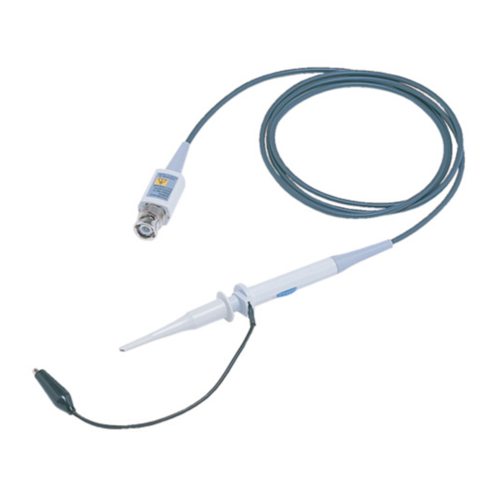
Description
The model 701940 is a 10 MHz passive probe with switchable attenuation ratio of 10:1 and 1:1.
This probe can be used for oscilloscopes with input impedances of 1 MΩ.
Appearance
This probe is composed of the probe and its accessories. Optional accessories are available to meet
various applications.
10:1 - 1:1 Switch
Orange
White
Trimmer
5
Green
Blue
screw
6
7
Standard Accessories
Name
Part No.
Optional Accessories
1
Ground lead
B9852CW
(Sold Separately)
2
Pinchers tip
B9852CX
3
IC test tip
B9852CY
4
Ground attachment
B9852CZ
5
Marker tip
B9852DH
AVERTISSEMENT
ATTENTION
1
2
3
4
Name
Part No.
6
Mini clip converter
B9852CR
7
BNC adapter
B9852CS
IM 701940-01E 1/2
Advertisement
Table of Contents

Subscribe to Our Youtube Channel
Related Manuals for YOKOGAWA 701940


Summary of Contents for YOKOGAWA 701940
- Page 1 Make sure to comply with the following safety precautions in order to prevent accidents Description such as an electric shock which impose serious health risks to the user and damage to the The model 701940 is a 10 MHz passive probe with switchable attenuation ratio of 10:1 and 1:1. instrument. This probe can be used for oscilloscopes with input impedances of 1 MΩ.
- Page 2 • Lors de l’utilisation de cette sonde pour une entrée isolée, vous devez l’utiliser en 42 V ou moins pour les côtés H et L. En particulier, la coque GND possède des parties métalliques exposées, d’où un risque de choc électrique élevé. Même lorsqu’un potentiel élevé existe uniquement sur le côté H, une haute tension peut tout de même être présente sur le côté L, créant ainsi une condition très dangereuse. • Même lorsque la tension de l’entrée non isolée ne dépasse pas le maximum, afin de s’assurer que le courant passe jusqu’au circuit protecteur de mise à la terre, la mise à la terre protectrice (du terminal à 3 broches de l’alimentation électrique) de l’unité principale doit être activée, et pour les modules enfichables, les vis de fixation du module doivent être bien serrées. • Cette sonde possède un commutateur 10:1 - 1:1. S’assurer de respecter les précautions suivantes lors de l’allumage de la sonde. • Confirmer la tension d’entrée maximum de l’oscilloscope lors de l’allumage de la sonde sur 1:1. Introduire accidentellement une entrée trop élevée peut endommager la section d’entrée. • Ne pas allumer la sonde au moment de la mise sous tension. Ceci est extrêmement dangereux. Max Input Voltage derating curve 1000 Frequency (MHz) IM 701940-01E 2/2...
Need help?
Do you have a question about the 701940 and is the answer not in the manual?
Questions and answers